EP1932976A1 - Toiture - Google Patents
Toiture Download PDFInfo
- Publication number
- EP1932976A1 EP1932976A1 EP06797609A EP06797609A EP1932976A1 EP 1932976 A1 EP1932976 A1 EP 1932976A1 EP 06797609 A EP06797609 A EP 06797609A EP 06797609 A EP06797609 A EP 06797609A EP 1932976 A1 EP1932976 A1 EP 1932976A1
- Authority
- EP
- European Patent Office
- Prior art keywords
- roof
- base material
- planar base
- concave
- gaps
- Prior art date
- Legal status (The legal status is an assumption and is not a legal conclusion. Google has not performed a legal analysis and makes no representation as to the accuracy of the status listed.)
- Withdrawn
Links
- 239000000463 material Substances 0.000 claims abstract description 81
- 238000009423 ventilation Methods 0.000 claims description 19
- 238000009413 insulation Methods 0.000 claims description 7
- 230000000694 effects Effects 0.000 abstract description 26
- 238000001816 cooling Methods 0.000 description 10
- 239000002184 metal Substances 0.000 description 7
- 239000004744 fabric Substances 0.000 description 5
- 238000005273 aeration Methods 0.000 description 4
- XLYOFNOQVPJJNP-UHFFFAOYSA-N water Substances O XLYOFNOQVPJJNP-UHFFFAOYSA-N 0.000 description 4
- 239000011347 resin Substances 0.000 description 3
- 229920005989 resin Polymers 0.000 description 3
- 206010022000 influenza Diseases 0.000 description 2
- 238000000034 method Methods 0.000 description 2
- 239000004753 textile Substances 0.000 description 2
- 239000004793 Polystyrene Substances 0.000 description 1
- 238000007796 conventional method Methods 0.000 description 1
- 238000013461 design Methods 0.000 description 1
- 230000002708 enhancing effect Effects 0.000 description 1
- 238000010438 heat treatment Methods 0.000 description 1
- 238000012986 modification Methods 0.000 description 1
- 230000004048 modification Effects 0.000 description 1
- 230000002093 peripheral effect Effects 0.000 description 1
- 229920002223 polystyrene Polymers 0.000 description 1
- 230000002265 prevention Effects 0.000 description 1
- 238000012545 processing Methods 0.000 description 1
- 230000001737 promoting effect Effects 0.000 description 1
- 239000012209 synthetic fiber Substances 0.000 description 1
- 229920002994 synthetic fiber Polymers 0.000 description 1
- 125000000391 vinyl group Chemical group [H]C([*])=C([H])[H] 0.000 description 1
- 229920002554 vinyl polymer Polymers 0.000 description 1
- 238000004078 waterproofing Methods 0.000 description 1
- 239000002023 wood Substances 0.000 description 1
Images


Classifications
-
- E—FIXED CONSTRUCTIONS
- E04—BUILDING
- E04D—ROOF COVERINGS; SKY-LIGHTS; GUTTERS; ROOF-WORKING TOOLS
- E04D13/00—Special arrangements or devices in connection with roof coverings; Protection against birds; Roof drainage ; Sky-lights
- E04D13/17—Ventilation of roof coverings not otherwise provided for
- E04D13/172—Roof insulating material with provisions for or being arranged for permitting ventilation of the roof covering
-
- E—FIXED CONSTRUCTIONS
- E04—BUILDING
- E04D—ROOF COVERINGS; SKY-LIGHTS; GUTTERS; ROOF-WORKING TOOLS
- E04D13/00—Special arrangements or devices in connection with roof coverings; Protection against birds; Roof drainage ; Sky-lights
-
- E—FIXED CONSTRUCTIONS
- E04—BUILDING
- E04D—ROOF COVERINGS; SKY-LIGHTS; GUTTERS; ROOF-WORKING TOOLS
- E04D3/00—Roof covering by making use of flat or curved slabs or stiff sheets
- E04D3/36—Connecting; Fastening
- E04D3/3608—Connecting; Fastening for double roof covering or overroofing
-
- E—FIXED CONSTRUCTIONS
- E04—BUILDING
- E04D—ROOF COVERINGS; SKY-LIGHTS; GUTTERS; ROOF-WORKING TOOLS
- E04D3/00—Roof covering by making use of flat or curved slabs or stiff sheets
- E04D3/36—Connecting; Fastening
- E04D3/366—Connecting; Fastening by closing the space between the slabs or sheets by gutters, bulges, or bridging elements, e.g. strips
-
- E—FIXED CONSTRUCTIONS
- E04—BUILDING
- E04F—FINISHING WORK ON BUILDINGS, e.g. STAIRS, FLOORS
- E04F10/00—Sunshades, e.g. Florentine blinds or jalousies; Outside screens; Awnings or baldachins
Definitions
- the present invention relates to roofs, and more specifically relates to roofs that prevent members forming the roofs from becoming high temperature by direct sunlight to thereby eliminate the influence on indoors.
- the present invention is intended to protect the roofs themselves from direct sunlight by a simple configuration, and also prevent the roofs from becoming high temperature by positively cooling them.
- a roof of the present invention is characterized in that a planar base material in which gaps penetrated through back and front sides are formed is arranged on a roof surface with a clearance between the roof and itself.
- the present invention according to claim 2 is characterized in that the planar base material in which the gaps penetrated through the back and front sides are provided has a net structure.
- the present invention according to claim 3 is characterized in that the planar base material in which the gaps penetrated through the back and front sides are provided is a sheet or a board material having bores scattered therein.
- the present invention according to claim 4 is characterized in that the planar base material in which the gaps penetrated through the back and front sides are provided is arranged on the roof surface with a concave-convex streak formed in a certain direction to form a ventilation flue in a space between the concave streak and the planar base material.
- the present invention according to claim 5 is the roof with the concave-convex streak formed in the certain direction, and characterized in that the ventilation flue is formed in the space between the concave streak and the sheet or the board material, and that the bores are provided in the sheet part or the board material part on this ventilation flue.
- the present invention according to claim 6 is characterized in that the planar base material is arranged from the inside except an end thereof in a direction of the concave-convex streak of the roof.
- the present invention according to claim 7 is characterized in that the planar base material has a heat insulation efficiency.
- the roof structure has an effect to prevent the temperature of the roof from becoming high due to shining down of direct sunlight on the upper surface of the roof, and makes air exist in the space formed between the roof and the planar base material, and can also be expected to have an aeration effect and an air cooling effect by air going in and out also from the gaps where air penetrates through the back and front sides, and further, has an effect to control the loose of the planar base material and discharge the rain water collected on the planar base material from the gaps which penetrate the back and front sides.
- Such effects are not brought about artificially or mechanically, but brought about using natural winds, so that it also has an economical effect which does not require a running cost.
- the present invention according to claim 2 is characterized in that the planar base material in which the gaps penetrated through the back and front sides are provided has a net structure
- the present invention according to claim 3 is characterized in that the planar base material in which the gaps penetrated through the back and front sides are provided is the sheet or the board material having bores scattered therein, wherein the material has an effect the ability of being used for the planar base material as they are without giving special processing or the like, and thus the aeration effect, the loose control effect, and the rain water discharge effect from the nets or bores are exerted.
- the roof since the roof has the roof surface with a concave-convex streak formed in a certain direction, the planar base material is arranged thereon, and the ventilation flue is formed in the space between the concave streak and the planar base material, the arranged planar base material itself has the effect to prevent direct sunlight or the like from shining down on the roof surface, while the wind can easily pass through the inside of the ventilation flue, so that air passes through inside of the flue to prevent the roof from heating and the air cooling effect can also be obtained for cooling the inside of the flue by air circulation.
- planar base material on the ventilation flue has the gaps penetrated through the back and front sides, air goes in and out freely also from the gaps penetrated through the back and front sides, so that the air circulation function is promoted to enhance the aeration effect and the air cooling effect, and the loose of the planar base material is further prevented, thus also providing an effect of promoting drainage of the rain water collected on the planar base material.
- Such effects are not brought about artificially or mechanically, but brought about naturally and also has an economical effect which does not require a running cost.
- planar base material is the sheet or the board material
- the bores are provided in the sheet part or the board material part on the ventilation flue formed in the space between the concave streak and the sheet or the board material, the aeration effect, the loose control effect, and the rain water discharge effect is fully exerted.
- the roof in which concave-convex streak is formed is composed of metal roof decks in many cases, is likely to become high temperature by direct sunlight, it receives benefits by the present invention.
- the planar base material is arranged from the inside except the end thereof in the direction of concave-convex streak of the roof, air certainly enter the formed ventilation flue from the end of the roof, thus further enhancing the air cooling effect in the concave streak part.
- the roof is formed of the planar base material with heat insulation efficiency, shading and heat insulation function of direct sunlight or the like are enhanced, thus increasing the effect of preventing the temperature of the roof from becoming high.
- the present invention could protect roofs themselves from direct sunlight with a simple configuration, and also could prevent the roofs from becoming high temperature by positively cooling them.
- FIG. 1 is a plan view of a roof showing one embodiment of the present invention
- FIGs.2 and 3 are principal part sectional views thereof, wherein it is configured that the planar base material 2 is arranged on a roof 1. It is effective to cover about 70 to 90% of the roof 1 with the planar base material 2.
- the roof 1 in the drawings is a low profile standing seam metal roofing roof of a flat roof, being removably attached with a bolt and nut 13 using an angle 6 of a snow stopper 5 which is attached to a cap 4 of a knot of a metal roofing board 3, and attachment holes 7 of a planar base material 2, and the planar base material 2 is arranged on the roof 1 while loosing from the surface of the roof 1 and providing a clearance 8 (about 50-90 mm) therebetween.
- the attachment holes 7 are disposed to the peripheral edge portion of the planar base material 2 at a predetermined pitch.
- the planar base material 2 is a thin board-like material or a sheet-like material, the material of which may be any kind of materials, such as wood, resin, metal, or cloth, and gaps 9 penetrated through a back and front sides are formed therein.
- the gaps 9 which penetrate through the back and front sides may be formed linearly or geometrically to be scattered regularly or arbitrarily.
- an opening rate of the overall through holes to the planar base material 2 is set to about 3 to 8 % and preferably 4 to 6 %.
- a textile net or a knitted net such as a resin net, a synthetic fiber net, a mesh cloth, a screen mesh, a bolting cloth, a wire net, or a net punched holes uniformly or the like, are provided with the gaps 9, so that they can be used for the planar base material 2 as they are.
- a tape-like material of thin width is woven or knitted to form the gaps 9, or a configuration arranging a stick material or a string material within a frame in the shape of barred lattice can also provide the streaky gaps 9, so that they can be used for the planar base material 2 as they are.
- the sheet a material which has tensile strength, such as various textile cloth, a vinyl cloth, a rubber material is desirable, and a material called a shade sheet variously processed, such as light-proof, heat resistance, waterproofing, or a cold gauze may be used.
- the thickness of the sheet is about 0.2-2.0 mm, preferably 0.4-0.8 mm.
- the board material although a single board of the various materials and a plyboard can be used without any limitations, a board as thin as possible is preferable.
- the thickness of the board material is about 2.0-20.0 mm.
- a corrugated board such as polystyrene or the like, a thin board made of resin with a heat insulation function, or a single board and a plyboard with a heat insulating layer on the surface are also desirable.
- a shape and a size of the through holes 9 formed in the sheet or the board material may adopt arbitrary one, and scattering of the through holes is designed appropriately based on a relation between an increase in roof temperature by sunlight passing therethrough and a ventilation circulation.
- the diameter of the through holes 9 is about 80-150 mm (preferably 100-120 mm) in a case of circular holes (refer to FIG.4 ).
- the roof 1 Since the roof 1 is blocked by the planar base material 2 without sunlight hitting directly, the temperature rise of the roof 1 itself can be prevented, even when the net planar base material is used, it has a block function of sunlight. Subsequently, since the space of the clearance 8 is formed between the roof 1 and the planar base material 2, and the planar base material 2 is provided with the gaps 9 and 9 ⁇ ⁇ ⁇ , air goes in and out and circulates from the ends and the gaps 9 of the planar base material 2 of the roof 1, so that the air in the space of the clearance 8 is aerated to thereby prevent the temperature in the space from becoming high, and the air cooling function of the roof 1 itself is also performed, and the loose of the planar base material 2 by the wind or the like can also be prevented.
- FIG.4 is a plan view of a roof showing another embodiment of the present invention
- FIGs.5 and 6 are principal part sectional views thereof, wherein it is configured that the planar base material 2 is arranged on the roof 1.
- the roof 1 is a flat roof which is gently inclined in a direction from the top to the bottom and is formed of a roof deck 10 in the drawing, and concave streaks (valley parts) 11 and convex streaks (mountain parts) 12 of the roof deck 10 are also arranged in the top to bottom direction along with an inclination in the drawing.
- the roof 1 may have concave-convex streaks formed thereon, so that means and configurations for forming the streak are not limited to a kind of roof deck, and a kind of roof is not considered, either.
- the planar base material is in removable fixed and arranged with the bolts and nuts 13 provided in a circumferential end of the roof 1 corresponding to the attachment holes 7 and 7 ⁇ ⁇ ⁇ provided in the circumference. Moreover, the gaps 9 and 9 ⁇ ⁇ ⁇ exist in the planar base material 2 on a ventilation flue 14 formed of the concave streak 11 of the roof 1 and the arranged planar base material 2.
- the air in the ventilation flue 14 goes in and out and circulates from the end and gaps of the concave streak of the planar base material 2, the air in the ventilation flue 14 is ventilated to be able to prevent the temperature from becoming high, and the air cooling function of the concave streak 11 of the roof 1 which forms the ventilation flue 14 or the planar base material 2 is also performed, and the loose of the planar base material 2 by the wind or the like can be also prevented.
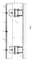
- FIG.7 is a plan view showing another embodiment, wherein a plurality of the planar base materials 2 and 2 ⁇ ⁇ ⁇ are mutually arranged on a plane-like roof 1 with an interval 15, and air can go in and out and circulate from the portion with the interval 15 to the ventilation flues 14.
- the interval 15 is about 10-500 mm.
- FIG.8 is a plan view showing another embodiment, wherein the planar base material 2 is arranged from the inside except the end 16 in the direction of the concave-convex streaks 11, 12 of the roof 1, so that air can easily go into the ventilation flues 14 from the end 16 which the planar base material 2 is not arranged thereon.
- the present invention can be used in areas where they are achieved not artificially or mechanically but using natural winds or the like, and reduction in running cost is required.
Landscapes
- Engineering & Computer Science (AREA)
- Architecture (AREA)
- Civil Engineering (AREA)
- Structural Engineering (AREA)
- Mechanical Engineering (AREA)
- Building Environments (AREA)
- Roof Covering Using Slabs Or Stiff Sheets (AREA)
Applications Claiming Priority (4)
| Application Number | Priority Date | Filing Date | Title |
|---|---|---|---|
| JP2005264656A JP3987550B2 (ja) | 2005-09-13 | 2005-09-13 | 屋根 |
| JP2006143480 | 2006-05-24 | ||
| JP2006233277A JP2008057155A (ja) | 2006-08-30 | 2006-08-30 | 屋根 |
| PCT/JP2006/317733 WO2007032250A1 (fr) | 2005-09-13 | 2006-09-07 | Toiture |
Publications (1)
| Publication Number | Publication Date |
|---|---|
| EP1932976A1 true EP1932976A1 (fr) | 2008-06-18 |
Family
ID=37864846
Family Applications (1)
| Application Number | Title | Priority Date | Filing Date |
|---|---|---|---|
| EP06797609A Withdrawn EP1932976A1 (fr) | 2005-09-13 | 2006-09-07 | Toiture |
Country Status (6)
| Country | Link |
|---|---|
| US (1) | US20090173024A1 (fr) |
| EP (1) | EP1932976A1 (fr) |
| KR (1) | KR20080036604A (fr) |
| AU (1) | AU2006290078B2 (fr) |
| MY (1) | MY152520A (fr) |
| WO (1) | WO2007032250A1 (fr) |
Families Citing this family (5)
| Publication number | Priority date | Publication date | Assignee | Title |
|---|---|---|---|---|
| MX2009007806A (es) * | 2007-01-23 | 2010-01-29 | Jacques Pigerre | Cubierta de protección contra el calor y el viento para construcciones. |
| US20150176283A1 (en) * | 2013-12-20 | 2015-06-25 | Bruce E. Smiley, JR. | Insulating panels |
| US9879414B2 (en) | 2015-05-12 | 2018-01-30 | Power Solutions International, Inc. | Three dimensional structural frames and enclosures |
| US10822791B2 (en) * | 2017-01-23 | 2020-11-03 | John G. Hoggatt | Drainage and ventilation mat for building exterior wall, roof and basement assemblies |
| JP6993091B2 (ja) * | 2017-03-27 | 2022-01-13 | 積水化学工業株式会社 | 太陽電池シートの施工構造 |
Family Cites Families (18)
| Publication number | Priority date | Publication date | Assignee | Title |
|---|---|---|---|---|
| JPS5262620U (fr) * | 1975-11-05 | 1977-05-09 | ||
| JPS54119117A (en) * | 1978-03-08 | 1979-09-14 | Mitsui Eng & Shipbuild Co Ltd | Sea-bottom oil storage tank |
| JPS5636806U (fr) * | 1979-08-31 | 1981-04-08 | ||
| JPS5818316A (ja) * | 1981-07-27 | 1983-02-02 | Sana Seiyaku Kk | フイルムコ−テイング製剤 |
| JPS59124232U (ja) * | 1983-02-08 | 1984-08-21 | 勝連 盛伸 | 日除け装置 |
| US4674249A (en) * | 1985-09-16 | 1987-06-23 | Carveth W Bennett Sr | Roofing and decking construction |
| US5088259A (en) * | 1987-11-16 | 1992-02-18 | Myers J Milton | Roof construction system |
| US5451445A (en) * | 1993-11-16 | 1995-09-19 | Wang; Tsu J. | Foldable net assembly |
| US5584153A (en) * | 1994-03-29 | 1996-12-17 | Loadmaster Systems, Inc. | Composite roof system with an improved anchoring mechanism |
| US5661937A (en) * | 1995-04-17 | 1997-09-02 | Johnson-Doppler Lumber | Mezzanine floor panel |
| US5787654A (en) * | 1995-09-21 | 1998-08-04 | Sport Court, Inc. | Isogrid tile |
| US5794402A (en) * | 1996-09-30 | 1998-08-18 | Martin Marietta Materials, Inc. | Modular polymer matrix composite support structure and methods of constructing same |
| US6161362A (en) * | 1998-04-27 | 2000-12-19 | Forbis, Sr.; Jack R. | Shade cover with evaporative cooling |
| US6401412B1 (en) * | 2000-04-10 | 2002-06-11 | John Cooper | Metal roof system |
| US20020081967A1 (en) * | 2000-12-27 | 2002-06-27 | Miller Nathan Allen | Great event |
| JP2003147918A (ja) * | 2001-08-30 | 2003-05-21 | Masami Tanaka | 折板屋根構造 |
| WO2003080956A1 (fr) * | 2002-03-21 | 2003-10-02 | Forbis Jack R Sr | Ensemble panneaux s'utilisant avec un toit reflechissant et procedes d'utilisation |
| US6990775B2 (en) * | 2003-06-18 | 2006-01-31 | Masonry Technology, Inc. | Moisture drainage product, wall system incorporating such product and method therefore |
-
2006
- 2006-09-07 EP EP06797609A patent/EP1932976A1/fr not_active Withdrawn
- 2006-09-07 WO PCT/JP2006/317733 patent/WO2007032250A1/fr not_active Ceased
- 2006-09-07 AU AU2006290078A patent/AU2006290078B2/en not_active Ceased
- 2006-09-07 KR KR1020087003547A patent/KR20080036604A/ko not_active Ceased
- 2006-09-07 US US12/066,751 patent/US20090173024A1/en not_active Abandoned
- 2006-09-07 MY MYPI20080519 patent/MY152520A/en unknown
Non-Patent Citations (1)
| Title |
|---|
| See references of WO2007032250A1 * |
Also Published As
| Publication number | Publication date |
|---|---|
| KR20080036604A (ko) | 2008-04-28 |
| US20090173024A1 (en) | 2009-07-09 |
| WO2007032250A1 (fr) | 2007-03-22 |
| AU2006290078A1 (en) | 2007-03-22 |
| MY152520A (en) | 2014-10-15 |
| AU2006290078B2 (en) | 2011-03-17 |
Similar Documents
| Publication | Publication Date | Title |
|---|---|---|
| US5092086A (en) | Gutter shield assembly | |
| DE69526743T2 (de) | Konturiertes ventilationssystem für metalldächer | |
| CA1188866A (fr) | Aerateur sur bord de toit | |
| DE4001766C2 (de) | First- oder Gratbelüftungselement für Pfannendächer | |
| US7836642B2 (en) | Roof edge windscreen | |
| US8161692B2 (en) | Roof edge vortex suppressor | |
| US8528271B1 (en) | Multi-module vent cover system for a roof ventilation vent | |
| EP1932976A1 (fr) | Toiture | |
| EP0724048B1 (fr) | Bande d'étanchéité enroulable pour faíte et/ou arête de couverture | |
| US4644704A (en) | Rain gutter debris eliminator | |
| US2802551A (en) | Structural unit | |
| DE20023457U1 (de) | Dachbedeckung | |
| CN223398300U (zh) | 一种防雨雪通风天窗 | |
| JP2008057155A (ja) | 屋根 | |
| DE4123313C2 (de) | Firstentlüftungselement | |
| DE202010008821U1 (de) | Trägervorrichtung für ein Photovoltaik- oder Solarkollektor-Modul | |
| AT275837B (de) | Schutzvorrichtung gegen Dachlawinen | |
| DE3316411C2 (fr) | ||
| AU716209B3 (en) | Improvements relating to the screening of guttering | |
| CN101263268A (zh) | 屋顶 | |
| JP5184936B2 (ja) | 屋根構造 | |
| AU726947B3 (en) | Mesh screen with improved system for fastening to rainwater guttering | |
| RU2522330C1 (ru) | Кровельное вентиляционное устройство | |
| EP3569789B1 (fr) | Bande d'aération pour l'arêtier ou le faîtage d'un toit | |
| BG64398B1 (bg) | Заслон срещу градушка |
Legal Events
| Date | Code | Title | Description |
|---|---|---|---|
| PUAI | Public reference made under article 153(3) epc to a published international application that has entered the european phase |
Free format text: ORIGINAL CODE: 0009012 |
|
| 17P | Request for examination filed |
Effective date: 20080328 |
|
| AK | Designated contracting states |
Kind code of ref document: A1 Designated state(s): AT BE BG CH CY CZ DE DK EE ES FI FR GB GR HU IE IS IT LI LT LU LV MC NL PL PT RO SE SI SK TR |
|
| STAA | Information on the status of an ep patent application or granted ep patent |
Free format text: STATUS: THE APPLICATION HAS BEEN WITHDRAWN |
|
| 18W | Application withdrawn |
Effective date: 20101110 |