EP1933034A2 - Drehkompressor - Google Patents
Drehkompressor Download PDFInfo
- Publication number
- EP1933034A2 EP1933034A2 EP08102934A EP08102934A EP1933034A2 EP 1933034 A2 EP1933034 A2 EP 1933034A2 EP 08102934 A EP08102934 A EP 08102934A EP 08102934 A EP08102934 A EP 08102934A EP 1933034 A2 EP1933034 A2 EP 1933034A2
- Authority
- EP
- European Patent Office
- Prior art keywords
- pressure
- vane
- pressure chamber
- refrigerant
- rotary
- Prior art date
- Legal status (The legal status is an assumption and is not a legal conclusion. Google has not performed a legal analysis and makes no representation as to the accuracy of the status listed.)
- Withdrawn
Links
- 230000006835 compression Effects 0.000 claims abstract description 176
- 238000007906 compression Methods 0.000 claims abstract description 176
- 239000003507 refrigerant Substances 0.000 claims description 219
- 238000007710 freezing Methods 0.000 claims description 7
- 230000008014 freezing Effects 0.000 claims description 7
- 241001131688 Coracias garrulus Species 0.000 description 87
- 239000003921 oil Substances 0.000 description 61
- 238000010586 diagram Methods 0.000 description 10
- 238000005192 partition Methods 0.000 description 10
- 230000010349 pulsation Effects 0.000 description 7
- CURLTUGMZLYLDI-UHFFFAOYSA-N Carbon dioxide Chemical compound O=C=O CURLTUGMZLYLDI-UHFFFAOYSA-N 0.000 description 6
- 239000007788 liquid Substances 0.000 description 5
- 238000001816 cooling Methods 0.000 description 4
- 230000000694 effects Effects 0.000 description 4
- 229910000831 Steel Inorganic materials 0.000 description 3
- 229910002092 carbon dioxide Inorganic materials 0.000 description 3
- 239000001569 carbon dioxide Substances 0.000 description 3
- 238000007599 discharging Methods 0.000 description 3
- 239000010959 steel Substances 0.000 description 3
- RTZKZFJDLAIYFH-UHFFFAOYSA-N Diethyl ether Chemical compound CCOCC RTZKZFJDLAIYFH-UHFFFAOYSA-N 0.000 description 2
- LYCAIKOWRPUZTN-UHFFFAOYSA-N Ethylene glycol Chemical compound OCCO LYCAIKOWRPUZTN-UHFFFAOYSA-N 0.000 description 2
- 238000004804 winding Methods 0.000 description 2
- 150000004996 alkyl benzenes Chemical class 0.000 description 1
- 230000003111 delayed effect Effects 0.000 description 1
- 239000010696 ester oil Substances 0.000 description 1
- 239000012530 fluid Substances 0.000 description 1
- WGCNASOHLSPBMP-UHFFFAOYSA-N hydroxyacetaldehyde Natural products OCC=O WGCNASOHLSPBMP-UHFFFAOYSA-N 0.000 description 1
- 238000010030 laminating Methods 0.000 description 1
- 239000000314 lubricant Substances 0.000 description 1
- 238000004519 manufacturing process Methods 0.000 description 1
- 239000002184 metal Substances 0.000 description 1
- 239000002480 mineral oil Substances 0.000 description 1
- 235000010446 mineral oil Nutrition 0.000 description 1
- 230000002093 peripheral effect Effects 0.000 description 1
Images


Classifications
-
- F—MECHANICAL ENGINEERING; LIGHTING; HEATING; WEAPONS; BLASTING
- F04—POSITIVE - DISPLACEMENT MACHINES FOR LIQUIDS; PUMPS FOR LIQUIDS OR ELASTIC FLUIDS
- F04C—ROTARY-PISTON, OR OSCILLATING-PISTON, POSITIVE-DISPLACEMENT MACHINES FOR LIQUIDS; ROTARY-PISTON, OR OSCILLATING-PISTON, POSITIVE-DISPLACEMENT PUMPS
- F04C29/00—Component parts, details or accessories of pumps or pumping installations, not provided for in groups F04C18/00 - F04C28/00
- F04C29/02—Lubrication; Lubricant separation
-
- F—MECHANICAL ENGINEERING; LIGHTING; HEATING; WEAPONS; BLASTING
- F04—POSITIVE - DISPLACEMENT MACHINES FOR LIQUIDS; PUMPS FOR LIQUIDS OR ELASTIC FLUIDS
- F04C—ROTARY-PISTON, OR OSCILLATING-PISTON, POSITIVE-DISPLACEMENT MACHINES FOR LIQUIDS; ROTARY-PISTON, OR OSCILLATING-PISTON, POSITIVE-DISPLACEMENT PUMPS
- F04C18/00—Rotary-piston pumps specially adapted for elastic fluids
- F04C18/30—Rotary-piston pumps specially adapted for elastic fluids having the characteristics covered by two or more of groups F04C18/02, F04C18/08, F04C18/22, F04C18/24, F04C18/48, or having the characteristics covered by one of these groups together with some other type of movement between co-operating members
- F04C18/34—Rotary-piston pumps specially adapted for elastic fluids having the characteristics covered by two or more of groups F04C18/02, F04C18/08, F04C18/22, F04C18/24, F04C18/48, or having the characteristics covered by one of these groups together with some other type of movement between co-operating members having the movement defined in group F04C18/08 or F04C18/22 and relative reciprocation between the co-operating members
- F04C18/356—Rotary-piston pumps specially adapted for elastic fluids having the characteristics covered by two or more of groups F04C18/02, F04C18/08, F04C18/22, F04C18/24, F04C18/48, or having the characteristics covered by one of these groups together with some other type of movement between co-operating members having the movement defined in group F04C18/08 or F04C18/22 and relative reciprocation between the co-operating members with vanes reciprocating with respect to the outer member
- F04C18/3562—Rotary-piston pumps specially adapted for elastic fluids having the characteristics covered by two or more of groups F04C18/02, F04C18/08, F04C18/22, F04C18/24, F04C18/48, or having the characteristics covered by one of these groups together with some other type of movement between co-operating members having the movement defined in group F04C18/08 or F04C18/22 and relative reciprocation between the co-operating members with vanes reciprocating with respect to the outer member the inner and outer member being in contact along one line or continuous surfaces substantially parallel to the axis of rotation
- F04C18/3564—Rotary-piston pumps specially adapted for elastic fluids having the characteristics covered by two or more of groups F04C18/02, F04C18/08, F04C18/22, F04C18/24, F04C18/48, or having the characteristics covered by one of these groups together with some other type of movement between co-operating members having the movement defined in group F04C18/08 or F04C18/22 and relative reciprocation between the co-operating members with vanes reciprocating with respect to the outer member the inner and outer member being in contact along one line or continuous surfaces substantially parallel to the axis of rotation the surfaces of the inner and outer member, forming the working space, being surfaces of revolution
-
- F—MECHANICAL ENGINEERING; LIGHTING; HEATING; WEAPONS; BLASTING
- F01—MACHINES OR ENGINES IN GENERAL; ENGINE PLANTS IN GENERAL; STEAM ENGINES
- F01C—ROTARY-PISTON OR OSCILLATING-PISTON MACHINES OR ENGINES
- F01C21/00—Component parts, details or accessories not provided for in groups F01C1/00 - F01C20/00
- F01C21/08—Rotary pistons
- F01C21/0809—Construction of vanes or vane holders
- F01C21/0818—Vane tracking; control therefor
- F01C21/0827—Vane tracking; control therefor by mechanical means
- F01C21/0845—Vane tracking; control therefor by mechanical means comprising elastic means, e.g. springs
-
- F—MECHANICAL ENGINEERING; LIGHTING; HEATING; WEAPONS; BLASTING
- F01—MACHINES OR ENGINES IN GENERAL; ENGINE PLANTS IN GENERAL; STEAM ENGINES
- F01C—ROTARY-PISTON OR OSCILLATING-PISTON MACHINES OR ENGINES
- F01C21/00—Component parts, details or accessories not provided for in groups F01C1/00 - F01C20/00
- F01C21/08—Rotary pistons
- F01C21/0809—Construction of vanes or vane holders
- F01C21/0818—Vane tracking; control therefor
- F01C21/0854—Vane tracking; control therefor by fluid means
- F01C21/0863—Vane tracking; control therefor by fluid means the fluid being the working fluid
-
- F—MECHANICAL ENGINEERING; LIGHTING; HEATING; WEAPONS; BLASTING
- F01—MACHINES OR ENGINES IN GENERAL; ENGINE PLANTS IN GENERAL; STEAM ENGINES
- F01C—ROTARY-PISTON OR OSCILLATING-PISTON MACHINES OR ENGINES
- F01C21/00—Component parts, details or accessories not provided for in groups F01C1/00 - F01C20/00
- F01C21/08—Rotary pistons
- F01C21/0809—Construction of vanes or vane holders
- F01C21/0818—Vane tracking; control therefor
- F01C21/0854—Vane tracking; control therefor by fluid means
- F01C21/0872—Vane tracking; control therefor by fluid means the fluid being other than the working fluid
-
- F—MECHANICAL ENGINEERING; LIGHTING; HEATING; WEAPONS; BLASTING
- F04—POSITIVE - DISPLACEMENT MACHINES FOR LIQUIDS; PUMPS FOR LIQUIDS OR ELASTIC FLUIDS
- F04C—ROTARY-PISTON, OR OSCILLATING-PISTON, POSITIVE-DISPLACEMENT MACHINES FOR LIQUIDS; ROTARY-PISTON, OR OSCILLATING-PISTON, POSITIVE-DISPLACEMENT PUMPS
- F04C18/00—Rotary-piston pumps specially adapted for elastic fluids
- F04C18/30—Rotary-piston pumps specially adapted for elastic fluids having the characteristics covered by two or more of groups F04C18/02, F04C18/08, F04C18/22, F04C18/24, F04C18/48, or having the characteristics covered by one of these groups together with some other type of movement between co-operating members
- F04C18/34—Rotary-piston pumps specially adapted for elastic fluids having the characteristics covered by two or more of groups F04C18/02, F04C18/08, F04C18/22, F04C18/24, F04C18/48, or having the characteristics covered by one of these groups together with some other type of movement between co-operating members having the movement defined in group F04C18/08 or F04C18/22 and relative reciprocation between the co-operating members
- F04C18/356—Rotary-piston pumps specially adapted for elastic fluids having the characteristics covered by two or more of groups F04C18/02, F04C18/08, F04C18/22, F04C18/24, F04C18/48, or having the characteristics covered by one of these groups together with some other type of movement between co-operating members having the movement defined in group F04C18/08 or F04C18/22 and relative reciprocation between the co-operating members with vanes reciprocating with respect to the outer member
-
- F—MECHANICAL ENGINEERING; LIGHTING; HEATING; WEAPONS; BLASTING
- F04—POSITIVE - DISPLACEMENT MACHINES FOR LIQUIDS; PUMPS FOR LIQUIDS OR ELASTIC FLUIDS
- F04C—ROTARY-PISTON, OR OSCILLATING-PISTON, POSITIVE-DISPLACEMENT MACHINES FOR LIQUIDS; ROTARY-PISTON, OR OSCILLATING-PISTON, POSITIVE-DISPLACEMENT PUMPS
- F04C23/00—Combinations of two or more pumps, each being of rotary-piston or oscillating-piston type, specially adapted for elastic fluids; Pumping installations specially adapted for elastic fluids; Multi-stage pumps specially adapted for elastic fluids
- F04C23/001—Combinations of two or more pumps, each being of rotary-piston or oscillating-piston type, specially adapted for elastic fluids; Pumping installations specially adapted for elastic fluids; Multi-stage pumps specially adapted for elastic fluids of similar working principle
-
- F—MECHANICAL ENGINEERING; LIGHTING; HEATING; WEAPONS; BLASTING
- F04—POSITIVE - DISPLACEMENT MACHINES FOR LIQUIDS; PUMPS FOR LIQUIDS OR ELASTIC FLUIDS
- F04C—ROTARY-PISTON, OR OSCILLATING-PISTON, POSITIVE-DISPLACEMENT MACHINES FOR LIQUIDS; ROTARY-PISTON, OR OSCILLATING-PISTON, POSITIVE-DISPLACEMENT PUMPS
- F04C23/00—Combinations of two or more pumps, each being of rotary-piston or oscillating-piston type, specially adapted for elastic fluids; Pumping installations specially adapted for elastic fluids; Multi-stage pumps specially adapted for elastic fluids
- F04C23/008—Hermetic pumps
-
- F—MECHANICAL ENGINEERING; LIGHTING; HEATING; WEAPONS; BLASTING
- F04—POSITIVE - DISPLACEMENT MACHINES FOR LIQUIDS; PUMPS FOR LIQUIDS OR ELASTIC FLUIDS
- F04C—ROTARY-PISTON, OR OSCILLATING-PISTON, POSITIVE-DISPLACEMENT MACHINES FOR LIQUIDS; ROTARY-PISTON, OR OSCILLATING-PISTON, POSITIVE-DISPLACEMENT PUMPS
- F04C2270/00—Control; Monitoring or safety arrangements
- F04C2270/56—Number of pump/machine units in operation
-
- F—MECHANICAL ENGINEERING; LIGHTING; HEATING; WEAPONS; BLASTING
- F04—POSITIVE - DISPLACEMENT MACHINES FOR LIQUIDS; PUMPS FOR LIQUIDS OR ELASTIC FLUIDS
- F04C—ROTARY-PISTON, OR OSCILLATING-PISTON, POSITIVE-DISPLACEMENT MACHINES FOR LIQUIDS; ROTARY-PISTON, OR OSCILLATING-PISTON, POSITIVE-DISPLACEMENT PUMPS
- F04C28/00—Control of, monitoring of, or safety arrangements for, pumps or pumping installations specially adapted for elastic fluids
Definitions
- the present invention relates to a multicylindrical rotary compressor constituted to be usable by switching a first operation mode in which first and second rotary compression elements perform compression works, and a second operation mode in which substantially the only first rotary compression element performs the compression work, a compression system provided with the multicylindrical rotary compressor, and a freezing device using the system.
- this type of compression system is constituted of a multicylindrical rotary compressor, a control unit which controls an operation of the multicylindrical rotary compressor and the like.
- This multicylindrical rotary compressor for example, a two-cylinder rotary compressor provided with first and second rotary compression elements is constituted by storing a driving element and the first and second rotary compression elements driven by a rotation shaft of the driving element in a sealed container.
- the first and second rotary compression elements include first and second cylinders, first and second rollers engaged with eccentric portions formed on the rotation shaft to rotate eccentrically in the respective cylinders, respectively, and first and second vanes which abut on the first and second rollers to divide each cylinder into low and high pressure chamber sides.
- the first and second vanes are constantly urged with respect to the first and second rollers by spring members.
- a low-pressure refrigerant gas is sucked from a suction passage into the low-pressure chamber side of the cylinder of each of the first and second rotary compression elements, and compressed by the operations of each roller and each vane to constitute the refrigerant gas at high temperature and pressure.
- the gas is discharged from the high-pressure chamber side of each cylinder into a discharge sound muffling chamber via a discharge port, the gas is discharged into the sealed container, and discharged to the outside (see, e.g., Japanese Patent Application Laid-Open No. 5-99172 ).
- a compression system in which a one-cylinder operation and a two-cylinder operation are switchable depending on capability. That is, one of the spring members which urge the first and second vanes of the multicylindrical rotary compressor with respect to the first and second rollers, for example, the spring member which urges the second vane with respect to the second roller is removed, and a refrigerant pressure on a discharge side of each of the rotary compression elements is applied as a back pressure of the second vane by the control unit at the time of the two-cylinder operation. Accordingly, the second vane is urged on the side of the second roller, and the compression work is performed.
- the control unit applies the refrigerant pressure on a suction side of each of the rotary compression elements as the back pressure of the second vane. Since this suction pressure is a low pressure, the second vane cannot be urged on the second roller side. Therefore, the compression work is not substantially performed in the second rotary compression element, and the compression work of the refrigerant is performed by the only first rotary compression element.
- the second rotary compression element which is not provided with the spring member has a problem that the refrigerant gas leaks from the second cylinder via a gap in the second vane during the two-cylinder operation. Especially at the time of low-speed rotation, a leak amount increases, and a remarkable drop of the compression efficiency is incurred.
- the present invention has been developed to solve such conventional technical problem, and an object thereof is to reduce collision noises of a second vane at a time when a first operation mode is switched to a second operation mode in a compression system provided with multicylindrical rotary compression elements constituted to be usable by urging an only first vane with respect to a first roller by a spring member to switch the first operation mode in which both of the rotary compression elements perform a compression work and the second operation mode in which substantially the only first rotary compression element performs the compression work.
- Another object is to improve a compression efficiency in the second rotary compression element and enhance a performance.
- a first aspect of the present invention is directed to a multicylindrical rotary compressor comprising a sealed container in which a driving element and first and second rotary compression elements driven by a rotation shaft of the driving element are contained, the first and second rotary compression elements including first and second cylinders; first and second rollers engaged with eccentric portions formed on the rotation shaft to rotate eccentrically in the respective cylinders, respectively; and first and second vanes which abut on the first and second rollers to divide each cylinder into a low-pressure chamber side and a high-pressure chamber side, the compressor being constituted to be usable by urging the only first vane with respect to the first roller by means of a spring member, and switching a pressure to be applied to a back-pressure chamber of the second vane to switch a first operation mode in which both of the rotary compression elements perform compression works and a second operation mode in which substantially the only first rotary compression element performs the compression work, wherein the pressure in the back-pressure chamber of the second vane is discharged to the low-pressure chamber side in the
- a second aspect of the present invention is directed to the multicylindrical rotary compressor of the first aspect of the present invention, which further comprises a communication path which connects the low-pressure chamber side in the second cylinder to the back-pressure chamber of the second vane, this communication path being connected only in an predetermined rotation region of the second roller.
- the pressure in the back-pressure chamber of the second vane is discharged on the low-pressure chamber side in the second cylinder. Therefore, for example, when there is disposed the communication path connected in the only predetermined rotation region of the second roller as in the second aspect of the present invention, and the pressure in the back-pressure chamber of the second vane is discharged to the low-pressure chamber side in the second cylinder, the pressure in the back-pressure chamber of the second vane can be released to the low-pressure chamber side in the second cylinder.
- the second vane can be retreated from the second cylinder early, and it is possible to reduce generation of collision between the second vane and the second roller.
- a third aspect of the present invention is directed to a compression system
- a compression system comprising a multicylindrical rotary compressor provided with a sealed container in which a driving element and first and second rotary compression elements driven by a rotation shaft of the driving element are contained, the first and second rotary compression elements including first and second cylinders; first and second rollers engaged with eccentric portions formed on the rotation shaft to rotate eccentrically in the respective cylinders, respectively; and first and second vanes which abut on the first and second rollers to divide each cylinder into a low-pressure chamber side and a high-pressure chamber side, the compressor being constituted to be usable by urging the only first vane with respect to the first roller by means of a spring member to switch a first operation mode in which both of the rotary compression elements perform compression works and a second operation mode in which substantially the only first rotary compression element performs the compression work, wherein an oil of an oil reservoir in the sealed container is supplied to a back-pressure chamber of the second vane in the first operation mode, and a su
- a fourth aspect of the present invention is directed to the multicylindrical rotary compressor of the third aspect of the present invention, wherein a refrigerant compressed by the first and second rotary compression elements is discharged into the sealed container.
- a fifth aspect of the present invention is directed to a freezing device wherein a refrigerant circuit is constituted using the compression system according to the third or fourth aspect of the present invention.
- the oil of the oil reservoir in the sealed container is supplied to the back-pressure chamber of the second vane in the first operation mode, it is possible to reduce leakages of a refrigerant gas from gaps of the second vane.
- the oil can be easily supplied to the back-pressure chamber owing to a pressure difference.
- the multicylindrical rotary compressor constituted to be usable by switching the first operation mode in which the first and second rotary compression elements perform the compression work and the second operation mode in which substantially the only first rotary compression element performs the compression work.
- the performance of the compression system can be remarkably enhanced.
- the refrigerant circuit of the freezing device is constituted using the compression system according to the above-described aspects of the present invention, it is possible to improve an operation efficiency and performance of the whole freezing device.
- FIG. 1 shows a vertical side view of a high inner pressure type rotary compressor 10 provided with first and second rotary compression elements according to an embodiment of a multicylindrical rotary compressor of the present invention
- FIG. 2 shows a vertical side view (showing a section different from that of FIG. 1 ) of the rotary compressor 10 of FIG. 1
- FIG. 3 shows a sectional plan view of a second cylinder 40 of a second rotary compression element 34.
- the rotary compressor 10 of the present embodiment constitutes a part of a refrigerant circuit of an air conditioner as a freezing device which conditions air in a room.
- the rotary compressor 10 of the present embodiment is the high inner pressure type rotary compressor.
- a vertically cylindrical sealed container 12 made of a steel plate there are stored an electromotive element 14 as a driving element disposed in an upper part of an inner space of this sealed container 12; and a rotary compression mechanism portion 18 disposed under this electromotive element 14 and constituted of first and second rotary compression elements 32, 34 driven by a rotation shaft 16 of the electromotive element 14.
- the sealed container 12 is constituted of a container main body 12A whose bottom portion is constituted as an oil reservoir and in which the electromotive element 14 and the rotary compression mechanism portion 18 are stored; and a substantially cup shaped end cap (lid member) 12B to close an upper opening of the container main body 12A. Moreover, a circular attaching hole 12D is formed in the upper surface of this end cap 12B, and a terminal (wiring line is omitted) 20 for supplying power to the electromotive element 14 is attached to the attaching hole 12D.
- a refrigerant discharge tube 96 is attached to the end cap 12B, and one end of the refrigerant discharge tube 96 communicates with the sealed container 12. Furthermore, a bottom part of the sealed container 12 is provided with an attaching base 110.
- the electromotive element 14 is constituted of a stator 22 welded and fixed in an annular form along an inner peripheral surface of an upper space of the sealed container 12; and a rotor 24 inserted with a slight interval inside this stator 22.
- This rotor 24 is fixed to the rotation shaft 16 which passes through the element and extends in a vertical direction.
- the stator 22 has a laminate 26 constituted by laminating donut-shaped electromagnetic steel plates; and a stator coil 28 wound around a tooth portion of the laminate 26 by a direct winding (concentrated winding) system.
- the rotor 24 is constituted of a laminate 30 of electromagnetic steel plates in the same manner as in the stator 22.
- first and second rotary compression elements 32, 34 are constituted of the intermediate partition plate 36; first and second cylinders 38, 40 disposed on and under this intermediate partition plate 36; first and second rollers 46, 48 fitted with upper and lower eccentric portions 42, 44 disposed on the rotation shaft 16 with a phase difference of 180 degrees in the first and second cylinders 38, 40 to rotate eccentrically in the respective cylinders 38, 40; first and second vanes 50, 52 whose tip portions abut on the first and second rollers 46, 48 to divide the respective cylinders 38, 40 into a low-pressure chamber side and a high-pressure chamber side, respectively; and an upper support member 54 and a lower support member 56 as support members which close an upper open surface of the first cylinder 38 and a lower open surface of the second cylinder 40 and which also function as bearings of the rotation shaft 16.
- the first and second cylinders 38, 40 are provided with suction passages 58, 60 which communicate with the first and second cylinders 38, 40 via suction ports 161 (the suction port of the first rotary compression element 32 is not shown).
- the suction passages 58, 60 are connected to refrigerant introducing pipes 92, 94 described later.
- a discharge sound muffling chamber 62 is disposed above the upper support member 54, and the refrigerant gas compressed by the first rotary compression element 32 is discharged to the discharge sound muffling chamber 62.
- This discharge sound muffling chamber 62 is formed in a substantially cup-shaped member 63 whose center is provided with a hole for passing the rotation shaft 16 and the upper support member 54 also functioning as the bearing of the rotation shaft 16 and which covers the upper support member 54 on the side of the electromotive element 14 (upper side).
- the electromotive element 14 is disposed above the cup member 63 with a predetermined interval from the cup member 63.
- the lower support member 56 is provided with a discharge sound muffling chamber 64 formed by closing a recessed portion formed in a lower part of the lower support member 56 with a cover as a wall. That is, the discharge sound muffling chamber 64 is closed by a lower cover 68 which defines the discharge sound muffling chamber 64. It is to be noted that the high-pressure chamber sides of the respective cylinders 38, 40 communicate with the respective discharge sound muffling chambers 62, 64 via discharge ports 49 (the discharge port of the first rotary compression element 32 is not shown).
- a guide groove 70 in which the first vane 50 is contained is formed in the first cylinder 38.
- a storage portion 70A in which a spring 74 as a spring member is stored is formed on a back-surface side of the first vane 50. This spring 74 abuts on an end portion of the first vane 50 on the back-surface side, and the first vane 50 is constantly urged on the side of the first roller 46.
- a discharge-side pressure (high pressure) in the sealed container 12 described later is also introduced into the storage portion 70A, and applied as a back pressure of the first vane 50.
- this storage portion 70A opens on the sides of the guide groove 70 and the sealed container 12 (container main body 12A).
- a plug 137 made of a metal is disposed on the side of the sealed container 12 of the spring 74 stored in the storage portion 70A, and prevents the spring 74 from falling.
- the second cylinder 40 is provided with a guide groove 72 in which the second vane 52 is stored, and a back-pressure chamber 72A is formed outside this guide groove 72, that is, on a back-surface side of the second vane 52.
- This back-pressure chamber 72A opens on the sides of the guide groove 72 and the sealed container 12, and a pipe 75 described later is connected to an opening on the side of the sealed container 12 to seal the pipe and the sealed container 12.
- Sleeves 141, 142 are welded and fixed to portions of the first and second cylinders 38, 40 corresponding to the suction passages 58, 60 on the side surface of the container main body 12A of the sealed container 12. Moreover, one end of the refrigerant introducing tube 92 for introducing the refrigerant gas into the first cylinder 38 is inserted into and connected to the sleeve 141, and one end of this refrigerant introducing tube 92 communicates with the suction passage 58 of the upper cylinder 38. The other end of the refrigerant introducing tube 92 opens in an accumulator 146.
- One end of the refrigerant introducing tube 94 for introducing the refrigerant gas into the second cylinder 40 is inserted into the sleeve 142, and one end of this refrigerant introducing tube 94 communicates with the suction passage 60 of the second cylinder 40.
- the other end of the refrigerant introducing tube 94 opens in the accumulator 146 in the same manner as in the refrigerant introducing tube 92.
- the accumulator 146 is a tank which separates a sucked refrigerant into a gas and a liquid, and attached to the side surface of an upper part of the container main body 12A of the sealed container 12 via a bracket 147. Moreover, the refrigerant introducing tubes 92, 94 are inserted into the accumulator 146 from a bottom part, and an opening of the other end of each tube is positioned in an upper part of the accumulator 146. One end of a refrigerant pipe 100 is inserted into the upper part of the accumulator 146.
- the discharge sound muffling chamber 64 communicates with the discharge sound muffling chamber 62 via a communication path 120 which passes through the first and second cylinders 38, 40 or the intermediate partition plate 36 in an axial center direction (vertical direction). Moreover, the high-temperature high-pressure refrigerant gas compressed by the second rotary compression element 34 and discharged to the discharge sound muffling chamber 64 is discharged to the discharge sound muffling chamber 62 via the communication path 120, and combined with the high-temperature high-pressure refrigerant gas compressed by the first rotary compression element 32.
- the discharge sound muffling chamber 62 communicates with the sealed container 12 via holes (not shown) which pass through the cup member 63, and the high-temperature high-pressure refrigerant gas compressed by the first and second rotary compression elements 32, 34 and discharged to the discharge sound muffling chamber 62 is discharged into the sealed container 12 via this hole.
- FIGS. 3 to 6 show sectional plan views of the second cylinder 40 (showing the operations of the second vane 52 and the second roller 48 of the second rotary compression element 34), respectively.
- This communication path 130 is a passage for connecting the low-pressure chamber side in the second cylinder 40 to the back-pressure chamber 72A of the second vane 52.
- the communication path 130 is formed in the intermediate partition plate 36 in the axial center direction (vertical direction), and constituted of a passage 131 which communicates with the back-pressure chamber 72A in the upper surface of the back-pressure chamber 72A; a passage 132 which is formed in the axial center direction in the intermediate partition plate 36 in the same manner as in the passage 131 and which communicates with the low-pressure chamber side in the second cylinder 40 in the upper surface of the second cylinder 40; and a passage 133 which is formed in the intermediate partition plate 36 in a horizontal direction and which communicates with the passages 131 and 132.
- a diameter of each of the passages 131 and 133 is set to 1.5 mm
- a diameter of the passage 132 which communicates with the low-pressure chamber side in the second cylinder 40 is set to 0.7 mm which is smaller than the diameter of each of the passages 131 and 132.
- An opening 131A of the passage 131 is openably closed by the second vane 52. That is, in a case where the second roller 48 is positioned in a top dead center as shown in FIG. 3 or in the vicinity of the top dead center (the second roller 48 is positioned in a region from the top dead center to a position rotated by 30° from the top dead center in the present embodiment) by an urging operation of the second vane 52 with respect to the second roller 48 in a forward/backward direction, a part of the second vane 52 is positioned right under the opening 131A. Therefore, the opening 131A is closed by the second vane 52. When the second roller 48 leaves the vicinity of the top dead center (the roller rotates by 30° or more from the top dead center in the present embodiment), the second vane 52 is detached from the opening 131A, and the opening 131A is opened.
- an opening 132A of the passage 132 is openably closed by the second vane 52 or the second roller 48. That is, in a case where the second roller 48 is positioned in the top dead center as shown in FIG. 3 or in the vicinity of the top dead center (the second roller 48 is positioned in a region from the top dead center to a position rotated by 60° from the top dead center in the present embodiment), a part of the second roller 48 is positioned right under the opening 132A, and the opening 132A is closed. When the second roller leaves the vicinity of the top dead center (the roller rotates by 70° or more from the top dead center in the present embodiment), a part of the second vane 52 is positioned right under the opening 132A, and the opening 132A is closed.
- the openings 132A and 131A are opened, and connected to the communication path 130 only in a predetermined rotation region of the second roller 48 (only in a rotation angle range of 60° or more and less than 70° in a rotating direction in a case where the top dead center of the second roller 48 is assumed as 0° in the present embodiment).
- the opening 131A is opened by the second vane 52.
- the opening 132A is opened by the second roller 48. Therefore, when the second roller 48 rotates by 60° from the top dead center, as shown in FIG. 7 , both of the openings 131A, 132A are opened and connected to the communication path 130. It is to be noted that FIG.
- FIG. 7 is a diagram showing a positional relation between the openings 131A and 132A of the passages 131 and 132 formed in the intermediate partition plate 36 and the second roller 48 and second vane 52 in a case where the second roller 48 rotates by 60° from the top dead center.
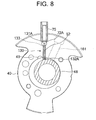
- FIG. 8 is a diagram showing a positional relation between the openings 131A and 132A of the passages 131 and 132 and the second roller 48 and second vane 52 in a case where the second roller 48 rotates by 70° from the top dead center.
- a refrigerant pipe 101 is connected to an intermediate portion of the refrigerant pipe 100, and the pipe is connected to the pipe 75 via an electromagnetic valve 105.
- a refrigerant pipe 102 is also connected to an intermediate portion of the refrigerant discharge tube 96, and connected to the pipe 75 via an electromagnetic valve 106 in the same manner as in the refrigerant pipe 101.
- These electromagnetic valves 105, 106 are controlled to open/close by a controller 210 described later. That is, when the electromagnetic valve 105 is opened, and the electromagnetic valve 106 is closed by the controller 210, the refrigerant pipe 101 is connected to the pipe 75.
- the refrigerant discharge tube 96 is connected to the pipe 75. Accordingly, a part of a discharge-side refrigerant of each of the rotary compression elements 32, 34, discharged from the sealed container 12 through the refrigerant discharge tube 96, flows from the pipe 75 into the back-pressure chamber 72A via the refrigerant pipe 102. Accordingly, the discharge-side pressures of both of the rotary compression elements 32, 34 are applied as a back pressure of the second vane 52.
- the controller 210 controls a rotation number of the electromotive element 14 of the rotary compressor 10. As described above, the electromagnetic valves 105, 106 of the refrigerant pipes 101, 106 are also controlled to open/close.
- FIG. 9 shows a refrigerant circuit diagram of an air conditioner constituted using the rotary compressor 10. That is, in the present embodiment, the rotary compressor 10 constitutes a part of the refrigerant circuit of the air conditioner shown in FIG. 9 .
- the refrigerant discharge tube 96 of the rotary compressor 10 is connected to an inlet of an exterior heat exchanger 152.
- the controller 210, the rotary compressor 10, and the exterior heat exchanger 152 are disposed in an exterior unit (not shown) of the air conditioner.
- a pipe connected to an outlet of this exterior heat exchanger 152 is connected to an expansion valve 154 as pressure reducing means, and a pipe extending out of the expansion valve 154 is connected to an interior heat exchanger 156.
- the expansion valve 154 and the interior heat exchanger 156 are disposed in an interior unit (not shown) of the air conditioner.
- the interior heat exchanger 156 on an outlet side is connected to the refrigerant pipe 100 of the rotary compressor 10.
- an HFC or HC-based refrigerant is used as the refrigerant, and existing oil such as mineral oil, alkyl benzene oil, ether oil, or ester oil is used as the oil as a lubricant.
- the first operation mode will be described in which both of the rotary compression elements 32, 34 perform compression works.
- the controller 210 controls the rotation number of the electromotive element 14 of the rotary compressor 10 based on an operation instruction input of an interior controller (not shown) disposed in the interior unit, and the interior has a usual or high load state
- the controller 210 executes the first operation mode.
- the controller 210 closes the electromagnetic valve 105 of the refrigerant pipe 101, and opens the electromagnetic valve 106 of the refrigerant pipe 102.
- the refrigerant pipe 102 is connected to the pipe 75, the discharge-side refrigerants of both of the rotary compression elements 32, 34 flow into the back-pressure chamber 72A, and the discharge-side pressures of both of the rotary compression elements 32, 34 are applied as the back pressure of the second vane 52.
- the low-pressure refrigerant flows from the refrigerant pipe 100 of the rotary compressor 10 into the accumulator 146. Since the electromagnetic valve 105 of the refrigerant pipe 100 is closed as described above, all the refrigerant passed through the refrigerant pipe 100 flows into the accumulator 146 without flowing into the pipe 75.
- the low-pressure refrigerant which has flown into the accumulator 146 is separated into a gas and a liquid. Thereafter, the only refrigerant gas enters the respective refrigerant discharge tubes 92, 94 which open in the accumulator 146.
- the low-pressure refrigerant gas which has entered the refrigerant introducing tube 92 is sucked into the first cylinder 38 of the first rotary compression element 32 on the low-pressure chamber side via the suction passage 58 and a suction port (not shown).
- the refrigerant gas sucked into the first cylinder 38 on the low-pressure chamber side is compressed by the operations of the first roller 46 and the first vane 50 to constitute a high-temperature high-pressure refrigerant gas, and the gas is discharged from the high-pressure chamber side of the first cylinder 38 to the discharge sound muffling chamber 62 through a discharge port (not shown).
- the low-pressure refrigerant gas which has entered the refrigerant introducing tube 94 is sucked into the second cylinder 40 of the second rotary compression element 34 on the low-pressure chamber side via the suction port 161.
- the refrigerant gas sucked into the second cylinder 40 on the low-pressure chamber side is compressed by the operations of the second roller 48 and the second vane 52.
- FIG. 3 when the second roller 48 rotates (the second roller 48 rotates clockwise in FIGS. 3 to 6 ) from the top dead center, and passes through the suction port 161, suction of the low-pressure refrigerant ends on the low-pressure chamber side in the second cylinder 40. Moreover, when the second roller 48 rotates by 30° from the top dead center, the opening 131A of the passage 131 closed by the second vane 52 is opened as described above. It is to be noted that at this time, since the opening 132A of the passage 132 communicating with the second cylinder 40 on the low-pressure chamber side is closed by the second roller 48, the communication path 130 is not connected yet.
- the opening 132A of the passage 132 closed by the second roller 48 is opened, and connected to the communication path 130. Accordingly, the high-pressure refrigerant gas in the back-pressure chamber 72A is discharged to the low-pressure chamber side in the second cylinder 40 via the communication path 130.
- the pressure in the cylinder 40 on the high-pressure chamber side constitutes a predetermined pressure, and is discharged from the discharge port 49.
- the opening 131A of the passage 131 in the back-pressure chamber 72A is closed by the second vane 52. It is to be noted that the high-pressure refrigerant gas in the cylinder 40 is discharged until the second roller 48 passes through the discharge port 49. When the second roller 48 passes through the discharge port 49, the discharge of the refrigerant gas ends.
- the refrigerant gas discharged from the high-pressure chamber side of the second cylinder 40 to the discharge sound muffling chamber 64 through the discharge port 49 is discharged to the discharge sound muffling chamber 62 via the communication path 120, and combined with the refrigerant compressed by the first rotary compression element 32.
- the combined refrigerant is discharged into the sealed container 12 from a hole (not shown) extending through the cup member 63.
- the refrigerant in the sealed container 12 is discharged to the outside from the refrigerant discharge tube 96 formed in the end cap 12B of the sealed container 12, and flows into the exterior heat exchanger 152.
- the electromagnetic valve 106 of the pipe 102 is opened as described above, a part of the discharge-side refrigerant of each of the rotary compression elements 32, 34, passed through the refrigerant discharge tube 96, enters the pipe 75 from the refrigerant pipe 102, and is applied as the back pressure of the second vane 52.
- the refrigerant gas which has flown into the exterior heat exchanger 152 releases heat there, a pressure of the gas is reduced by the expansion valve 154, and the gas flows into the interior heat exchanger 156.
- the refrigerant evaporates in the interior heat exchanger 156, and absorbs heat from air circulated in a room to thereby exert a cooling function and cool the room.
- the refrigerant flows out of the interior heat exchanger 156, and is sucked into the rotary compressor 10. This cycle is repeated.
- This second operation mode is a mode in which substantially the only first rotary compression element 32 performs the compression work.
- This operation mode is carried out in a case where the inside of the room has a light load, and the electromotive element 14 rotates at a low speed in the first operation mode.
- substantially the only first rotary compression element 32 performs the compression work in a small capability region of the rotary compressor 10
- an amount of the refrigerant gas to be compressed can be reduced as compared with a case where both of the first and second cylinders 38, 40 perform the compression work. Therefore, the rotation number of the electromotive element 14 is raised as much even under the light load, the operation efficiency of the electromotive element 14 is improved, and it is possible to reduce leakage losses of the refrigerant.
- the controller 210 opens the electromagnetic valve 105 of the refrigerant pipe 101, and closes the electromagnetic valve 106 of the refrigerant pipe 102. Accordingly, the refrigerant pipe 101 communicates with the pipe 75, and the low-pressure refrigerant on the suction side of the first rotary compression element 32 flows into the back-pressure chamber 72A.
- the high-pressure refrigerant on the discharge side applied to the back-pressure chamber 72A of the second vane 52 in the first operation mode remains in the back-pressure chamber 72A. Therefore, much time has heretofore been required until the pressure in the back-pressure chamber 72A of the second vane 52 switches to the low pressure. That is, the second vane 52 is pushed by the high-pressure gas left in the back-pressure chamber 72A, and enters the second cylinder 40. This causes a problem that the second vane 52 collides with the second roller 48 to generate collision noises.
- the communication path 130 is connected to a predetermined rotation region (a rotation angle range of 60° or more and less than 70° as described above in the present embodiment) of the second roller 48, and the high pressure in the back-pressure chamber 72A is discharged to the low-pressure chamber side of the second cylinder 40 as in the present invention, the high pressure in the back-pressure chamber 72A can be released to the low-pressure chamber side in the second cylinder 40.
- a predetermined rotation region a rotation angle range of 60° or more and less than 70° as described above in the present embodiment
- the pressure in the back-pressure chamber 72A of the second vane 52 is quickly lowered, and the low pressure which is the suction-side pressure of the first rotary compression element 32 is applied as the back pressure of the second vane 52. Therefore, the second vane 52 can be retreated from the second cylinder 40 early, and it is possible to reduce the collision of the second vane 52 with the second roller 48.
- the communication path 130 is connected by the rotation by 60° in the rotating direction as described above.
- the pressure in the back-pressure chamber 72A is discharged to the low-pressure chamber side in the second cylinder 40, and the roller rotates by 10° from the position (the second roller 48 rotates by 70° from the top dead center in the rotating direction)
- the communication path 130 is closed, and the discharging of the pressure to the low-pressure chamber side in the second cylinder 40 is stopped.
- the second roller 48 in a case where the pressure of the back-pressure chamber 72A of the second roller 48 is higher than that of the low-pressure chamber side in the second cylinder 40, the second roller 48 always rotates by 60° in the rotating direction to discharge the pressure from the back-pressure chamber 72A into the second cylinder 40.
- the low-pressure refrigerant flows from the refrigerant pipe 100 of the rotary compressor 10 into the accumulator 146.
- the electromagnetic valve 105 of the refrigerant pipe 101 is opened as described above, a part of the refrigerant of the first rotary compression element 32 on the suction side, passed through the refrigerant pipe 100, flows from the refrigerant pipe 101 into the back-pressure chamber 72A through the pipe 75.
- the back-pressure chamber 72A has the suction-side pressure of the first rotary compression element 32 as described above, and the suction-side pressure of the first rotary compression element 32 is applied as the back pressure of the second vane 52.
- the low-pressure refrigerant which has flown into the accumulator 146 is separated into the gas and the liquid, and thereafter the only refrigerant gas enters the refrigerant discharge tube 92 which opens in the accumulator 146.
- the low-pressure refrigerant gas which has entered the refrigerant introducing tube 92 is sucked into the low-pressure chamber side of the first cylinder 38 of the first rotary compression element 32 through the suction passage 58 and a suction port (not shown).
- the refrigerant gas sucked into the low-pressure chamber side of the first cylinder 38 is compressed by the operations of the first roller 46 and the first vane 50 to constitute a high-temperature high-pressure refrigerant gas, and the gas is discharged from the high-pressure chamber side of the first cylinder 38 into the discharge sound muffling chamber 62 through a discharge port (not shown).
- the refrigerant gas discharged to the discharge sound muffling chamber 62 is discharged into the sealed container 12 through a hole (not shown) extending through the cup member 63.
- the refrigerant in the sealed container 12 is discharged to the outside from the refrigerant discharge tube 96 formed in the end cap 12B of the sealed container 12, and flows into the exterior heat exchanger 152.
- the refrigerant gas which has flown into the exterior heat exchanger 152 releases the heat there, the pressure of the gas is reduced by the expansion valve 154, and the gas flows into the interior heat exchanger 156.
- the refrigerant evaporates, and absorbs the heat from the air circulated in the room to exert the cooling function and cool the room.
- the refrigerant flows out of the interior heat exchanger 156, and is sucked into the rotary compressor 10. This cycle is repeated.
- the communication path 130 communicates, and the pressure is discharged from the back-pressure chamber 72A into the low-pressure chamber side of the second cylinder 40.
- the communication path 130 is closed, and the discharging of the pressure to the low-pressure chamber side in the second cylinder 40 is stopped.
- the position of the communication path 130 is not limited to that of the present embodiment as long as the communication path 130 communicates in the only predetermined rotation range of the second roller 48, for example, in any position where the second roller 48 rotates by 20° to 120° from the top dead center, the pressure is discharged from the back-pressure chamber 72A to the low-pressure chamber side in the second cylinder 40, and thereafter the discharging of the pressure from the second cylinder 40 into the low-pressure chamber side is stopped.
- the opening/closing valve may open to open the communication path.
- the pressure in the back-pressure chamber 72A is not discharged to the low-pressure chamber side of the second cylinder 40 in the first operation mode, it is possible to avoid the drop of the volume efficiency of the second rotary compression element 34.
- the high pressure which is the refrigerant pressure of the discharge side of each of the rotary compression elements 32, 34 is applied as the back pressure of the second vane 52 in the first operation mode in the present embodiment, but, for example, a pressure (intermediate pressure) between the discharge-side refrigerant pressure and the suction-side refrigerant pressure may be applied as the back pressure of the second vane 52.
- a valve device is disposed in an intermediate portion of the pipe 75, the valve device is closed, and the flowing of the refrigerant into the back-pressure chamber 72A is inhibited.
- the valve device is closed to stop the flowing of the high-pressure refrigerant from the pipe 75 into the back-pressure chamber 72A, and the inside of the back-pressure chamber 72A is set to the intermediate pressure, the second vane 52 can be sufficiently urged toward the second roller 48 without using any spring member.
- the second vane 52 when the first operation mode is switched to the second operation mode, the second vane 52 can be retreated from the second cylinder 40 early, and it is possible to reduce the collisions between the second vane 52 and the second roller 48.
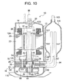
- FIG. 10 shows a vertical side view of a high inner pressure type rotary compressor 10 provided with first and second rotary compression elements as an embodiment of a multicylindrical rotary compressor of a compression system CS according to the present invention
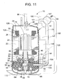
- FIG. 11 shows a vertical side view (showing a section different from that of FIG. 10 ) of the rotary compressor 10 of FIG. 10
- FIG. 12 shows a refrigerant circuit diagram of an air conditioner constituted using the compression system CS.
- the compression system CS of the present embodiment constitutes a part of a refrigerant circuit of the air conditioner as a freezing device which conditions the inside of a room in the same manner as in the above-described embodiment.
- components denoted with the same reference numerals as those of FIGS. 1 to 9 are regarded as components which produce similar effects, and description thereof is omitted.
- reference numeral 13 denotes an oil reservoir formed in a bottom part of a sealed container 12
- 148 denotes a communication tube connected to an inner bottom part of an accumulator 146, and oil accumulated in the accumulator 146 is returned to the oil reservoir 13 in the sealed container 12 via the communication tube 148.
- a refrigerant pipe 101 is connected to an intermediate portion of a refrigerant pipe 100 whose one end is inserted into an upper part of the accumulator 146, and the pipe is connected to a four-way changeover valve 107.
- One end of a pipe 102 is also connected to the oil reservoir 13 in a bottom part of the sealed container 12.
- One end of the pipe 102 is connected to the oil reservoir 13 as described above, and rises upwards, and the other end thereof is connected to the four-way changeover valve 107 in the same manner as in the refrigerant pipe 101.
- the four-way changeover valve 107 is connected to a pipe 75.
- a controller 210 is a control unit constituting a part of the compression system CS of the present invention, and controls a rotation number of an electromotive element 14 of the rotary compressor 10. Switching of the four-way changeover valve 107 is also controlled.
- the four-way changeover valve 107 is switchable by a solenoid coil 108. That is, when a power supply is OFF, the four-way changeover valve 107 has a state in which the pipe 102 of the oil is connected to the pipe 75.
- the power supply of the four-way changeover valve 107 is turned on based on an ON-signal from the controller 210, a magnetic field is generated in the solenoid coil 108. Accordingly, the four-way changeover valve 107 is switched to connect the refrigerant pipe 101 to the pipe 75.
- an OFF-signal input from the controller 210 the power supply of the four-way changeover valve 107 is turned off, and the pipe 102 is connected to the pipe 75 via the four-way changeover valve 107 as described above.
- the first operation mode will be described in which both of rotary compression elements 32, 34 perform compression works.
- the controller 210 controls the rotation number of the electromotive element 14 of the rotary compressor 10 based on an operation instruction input of an interior controller (not shown) disposed in an interior unit described above, and the interior has a usual or high load state
- the controller 210 executes the first operation mode.
- the four-way changeover valve 107 remains in the OFF-state. That is, the pipe 102 is connected to the pipe 75 via the four-way changeover valve 107 ( FIG. 13 ).
- a low-pressure refrigerant flows from the refrigerant pipe 100 of the rotary compressor 10 into the accumulator 146. Since the refrigerant pipe 101 is not connected to the pipe 75 via the four-way changeover valve 107 as described above, all the refrigerant passed through the refrigerant pipe 100 flows into the accumulator 146 without flowing into the pipe 75.
- the low-pressure refrigerant which has flown into the accumulator 146 is separated into a gas and a liquid. Thereafter, the only refrigerant gas enters refrigerant discharge tubes 92, 94 which open in the accumulator 146.
- the low-pressure refrigerant gas which has entered the refrigerant introducing tube 92 is sucked into the first cylinder 38 of the first rotary compression element 32 on a low-pressure chamber side via a suction passage 58.
- the refrigerant gas sucked into the first cylinder 38 on the low-pressure chamber side is compressed by the operations of the first roller 46 and a first vane 50 to constitute a high-temperature high-pressure refrigerant gas, and the gas is discharged from the high-pressure chamber side of the first cylinder 38 to a discharge sound muffling chamber 62 through a discharge port (not shown).
- the low-pressure refrigerant gas which has entered the refrigerant introducing tube 94 is sucked into the second cylinder 40 of a second rotary compression element 34 on the low-pressure chamber side via a suction passage 60.
- the refrigerant gas sucked into the second cylinder 40 on the low-pressure chamber side is compressed by the operations of the second roller 48 and the second vane 52.
- the oil in the oil reservoir 13 is supplied to a back-pressure chamber 72A via the pipe 102, the four-way changeover valve 107, and the pipe 75. Since the oil has a high pressure in the same manner as in the sealed container 12, such high-pressure oil (hydraulic pressure) is applied as a back pressure of the second vane 52. Accordingly, the second vane 52 can be sufficiently urged with respect to the second roller 48 without using any spring member.
- the refrigerant gas in the second cylinder 40 does not easily leak owing to a fluid difference (oil has a viscosity which is higher than that of the refrigerant gas) between the oil and the refrigerant gas, and leakages of the refrigerant gas can be remarkably reduced. Consequently, a compression efficiency in the second rotary compression element 34 can be improved.
- the high-temperature high-pressure refrigerant gas compressed by the operations of the second roller 48 and the second vane 52 is discharged from the high-pressure chamber side of the second cylinder 40 to a discharge sound muffling chamber 64 through a discharge port (not shown).
- the refrigerant gas discharged to the discharge sound muffling chamber 64 is discharged to the discharge sound muffling chamber 62 via the communication path 120, and combined with the refrigerant gas compressed by the first rotary compression element 32.
- the combined refrigerant gas is discharged into the sealed container 12 from a hole (not shown) extending through a cup member 63.
- the inside of the sealed container 12 can be set to a high pressure.
- the oil of the oil reservoir 13 in the bottom part of the sealed container 12 can be easily supplied to the back-pressure chamber 72A via the pipe 102 by use of a pressure difference.
- the oil mixed in the high-pressure refrigerant gas can be separated while passing through the sealed container 12, and an amount of the oil discharged to the outside of the rotary compressor 10 can be reduced.
- the refrigerant discharged into the sealed container 12 is discharged to the outside from a refrigerant discharge tube 96 formed in an end cap 12B of the sealed container 12, and flows into an exterior heat exchanger 152. There, the refrigerant gas releases heat, a pressure of the gas is reduced by an expansion valve 154, and the gas flows into an interior heat exchanger 156. The refrigerant evaporates in the interior heat exchanger 156, and absorbs heat from air circulated in a room to thereby exert a cooling function and cool the room. Moreover, the refrigerant flows out of the interior heat exchanger 156, and is sucked into the rotary compressor 10. This cycle is repeated.
- the high-pressure oil is supplied to the back-pressure chamber 72A in the first operation mode, but the present invention is not limited to this mode.
- the pipe 75 may be provided with an electromagnetic valve 105 as a valve device as shown by a broken line in FIG. 2 , and the electromagnetic valve 105 may be closed to set the inside of the back-pressure chamber 72A to an intermediate pressure. That is, after supplying the oil into the back-pressure chamber 72A as described above, the electromagnetic valve 105 is closed by the controller 210 to stop the flowing of the oil into the back-pressure chamber 72A. In this case, the oil supplied to the back-pressure chamber 72A remains in the back-pressure chamber 72A.
- an ON-signal is transmitted to the four-way changeover valve 107, and the power supply of the four-way changeover valve 107 is turned ON by the controller 210. Accordingly, a magnetic field of the solenoid coil 108 is generated, the four-way changeover valve 107 is switched, and the refrigerant pipe 101 is connected to the pipe 75. In this case, the high-pressure oil remaining in the pipe 75 enters the refrigerant pipe 101 via the four-way changeover valve 107 owing to a pressure difference. The oil enters the accumulator 146 together with the low-pressure refrigerant gas in the refrigerant pipe 100. After the oil is once stored in the accumulator 146, the oil is returned from the communication tube 148 into the oil reservoir 13 in the sealed container 12.
- the electromagnetic valve 105 when the pipe 75 is provided with the electromagnetic valve 105, the electromagnetic valve 105 is closed, and the high-pressure oil is inhibited from being supplied from the pipe 75 to set the inside of the back-pressure chamber 72A to the intermediate pressure, the second vane 52 can be sufficiently urged with respect to the second roller 48 without using any spring member in the same manner as described above.
- pressure pulsations can be reduced by effects of the oil and the intermediate pressure in the back-pressure chamber 72A, and followability of the second vane 52 can be enhanced more as compared with a case where the high-pressure oil in the sealed container 12 is supplied.
- This second operation mode is a mode in which substantially the only first rotary compression element 32 performs the compression work.
- This operation mode is carried out in a case where the inside of the room has a light load, and the electromotive element 14 rotates at a low speed in the first operation mode.
- substantially the only first rotary compression element 32 performs the compression work in a small capability region of the compression system CS, an amount of the refrigerant gas to be compressed can be reduced as compared with a case where both of the first and second cylinders 38, 40 perform the compression work.
- the rotation number of the electromotive element 14 is raised as much even under the light load, the operation efficiency of the electromotive element 14 is improved, and it is possible to reduce leakage losses of the refrigerant. It is to be noted that at a time when the mode is switched, the controller 210 rotates the electromotive element 14 at a low speed, and executes a control in such a manner as to set a rotation number to 40 Hz or less and a compression ratio to 3.0 or less.
- the ON-signal is input into the four-way changeover valve 107, and the power supply of the four-way changeover valve 107 is turned ON by the controller 210. Accordingly, the magnetic field of the solenoid coil 108 is generated, the four-way changeover valve 107 is switched, the refrigerant pipe 101 is connected to the pipe 75, the suction-side refrigerant of the first rotary compression element 32 flows into the back-pressure chamber 72A, and the suction-side pressure of the first rotary compression element 32 is applied as the back pressure of the second vane 52.
- the controller 210 energizes the stator coil 28 of the electromotive element 14 via the terminal 20 and a wiring line (not shown) as described above, and rotates the rotor 24 of the electromotive element 14. According to this rotation, the first and second rollers 46, 48 are fitted with the upper and lower eccentric portions 42, 44 disposed integrally with the rotation shaft 16 to eccentrically rotate in the first and second cylinders 38, 40.
- the low-pressure refrigerant flows from the refrigerant pipe 100 of the rotary compressor 10 into the accumulator 146.
- the refrigerant pipe 101 is connected to the pipe 75 via the four-way changeover valve 107 as described above, a part of the suction-side refrigerant of the first rotary compression element 32, passed through the refrigerant pipe 100, flows from the refrigerant pipe 101 into the back-pressure chamber 72A via the pipe 75.
- the back-pressure chamber 72A obtains the suction-side pressure of the first rotary compression element 32, and the suction-side pressure of the first rotary compression element 32 is applied as the back pressure of the second vane 52.
- the suction-side pressure of the first rotary compression element 32 is applied as the back pressure of the second vane 52
- the refrigerant pressure sucked into the second cylinder 40 is a low pressure equal to the back pressure of the second vane 52. Therefore, the second vane 52 cannot follow the second roller 48. Accordingly, since the second vane 52 retreats from the second cylinder 40, and the refrigerant cannot be compressed by the second rotary compression element 34, the refrigerant is compressed by the only first rotary compression element 32.
- the high-pressure refrigerant gas on the discharge side of each of the rotary compression elements 32, 34 having large pulsation is applied as the back pressure of the second rotary compression element 34.
- the discharge-side high-pressure refrigerant applied to the back-pressure chamber 72A of the second vane 52 in the first operation mode remains in the back-pressure chamber 72A, much time is required until the inside of the back-pressure chamber 72A of the second vane 52 changes to the low pressure. That is, the second vane 52 is pushed by the high-pressure gas left in the back-pressure chamber 72A, and enters the second cylinder 40. Therefore, the second vane 52 cannot be retreated from the second cylinder 40 early.
- the second vane 52 can be retreated from the second cylinder 40 early, and it is possible to reduce collisions between the second vane 52 and the second roller 48.
- the oil (high pressure) supplied to the back-pressure chamber 72A in the first operation mode flows out of the back-pressure chamber 72A owing to the pressure difference from the suction-side pressure, enters the refrigerant pipe 101 via the pipe 75 and the four-way changeover valve 107, and further enters the accumulator 146 together with the low-pressure refrigerant gas in the refrigerant pipe 100. After the oil is once stored in the accumulator 146, it is returned from the communication tube 148 back into the oil reservoir 13 in the sealed container 12.
- the only refrigerant gas enters the refrigerant introducing tube 92 that opens in the accumulator 146.
- the low-pressure refrigerant gas which has entered the refrigerant introducing tube 92 is sucked into the low-pressure chamber side of the first cylinder 38 of the first rotary compression element 32 via the suction passage 58.
- the refrigerant gas sucked into the low-pressure chamber side of the first cylinder 38 is compressed by the operations of the first roller 46 and the first vane 50 to constitute a high-temperature high-pressure refrigerant gas.
- the gas is discharged from the high-pressure chamber side of the first cylinder 38 into the discharge sound muffling chamber 62 through a discharge port (not shown).
- the discharge sound muffling chamber 62 functions as an expandable muffling chamber
- the discharge sound muffling chamber 64 functions as a resonant muffling chamber in the second operation mode, it is possible to reduce pressure pulsations of the refrigerant compressed by the first rotary compression element 32. Consequently, a sound muffling effect can be enhanced more in the second operation mode in which substantially the only first rotary compression element 32 performs the compression work.
- the refrigerant gas discharged to the discharge sound muffling chamber 62 is discharged into the sealed container 12 via a hole (not shown) extending through the cup member 63. Thereafter, the refrigerant in the sealed container 12 is discharged to the outside from the refrigerant discharge tube 96 formed in the end cap 12B of the sealed container 12, and flows into the exterior heat exchanger 152. After the refrigerant gas discharges heat in the heat exchanger, and the pressure is reduced by the expansion valve 154, the gas flows into the interior heat exchanger 156. The refrigerant evaporates in the interior heat exchanger 156, and absorbs the heat from the air circulated in the room to thereby exert the cooling function and cool the room. Moreover, the refrigerant flows out of the interior heat exchanger 156, and is sucked into the rotary compressor 10. This cycle is repeated.
- the present invention it is possible to enhance a performance and reliability of the compression system CS provided with the rotary compressor 10 constituted to be usable by switching the first operation mode in which the first and second rotary compression elements 32, 34 perform the compression work and the second operation mode in which substantially the only the first rotary compression element 32 performs the compression work.
- an four-way changeover valve 107 when a power supply is OFF, an four-way changeover valve 107 is brought into a state in which a pipe 102 of oil communicates with a pipe 75.
- a refrigerant pipe 101 is connected to the pipe 75.
- the refrigerant pipe 101 may be connected to the pipe 75 in a case where the power supply is OFF, and the oil pipe 102 may be connected to the pipe 75 in a case where the power supply of the four-way changeover valve 107 is turned ON based on the ON-signal from the controller 210.
- the power supply of the four-way changeover valve 107 is turned off, the four-way changeover valve 107 is switched, and the refrigerant pipe 101 is connected to the pipe 75.
- the high-pressure oil remaining in the pipe 75 enters the refrigerant pipe 101 via the four-way changeover valve 107 owing to the pressure difference.
- the oil then enters an accumulator 146 together with a low-pressure refrigerant gas in a refrigerant pipe 100, and is once stored in the accumulator 146. Thereafter, the oil is returned from a communication tube 148 back into an oil reservoir 13 in a sealed container 12.
- the electromagnetic valve 105 when the pipe 75 is provided with the electromagnetic valve 105, the electromagnetic valve 105 is closed to stop the high-pressure oil from being supplied from the pipe 75, and the inside of the back-pressure chamber 72A is set to the intermediate pressure, the second vane 52 can be sufficiently urged with respect to the second roller 48 without using any spring member in the same manner as described above. Moreover, it is possible to reduce pressure pulsations by effects of the oil and the intermediate pressure in the back-pressure chamber 72A, and followability of the second vane 52 can be enhanced more.
- an HFC or HC-based refrigerant is used as the refrigerant, but a refrigerant such as carbon dioxide having a large pressure difference, such as carbon dioxide combined with polyalkyl glycol (PAG), may be used.
- a refrigerant such as carbon dioxide having a large pressure difference, such as carbon dioxide combined with polyalkyl glycol (PAG)
- PAG polyalkyl glycol
- the refrigerant compressed by each of rotary compression elements 32, 34 has a very high pressure. Therefore, when a discharge sound muffling chamber 62 is formed into such a shape to cover an upper support member 54 from above by means of a cup member 63, the cup member 63 might be broken by such high pressure.
- the discharge sound muffling chamber above the upper support member 54 in which the refrigerants compressed by both of the rotary compression elements 32, 34 are combined is formed into a recessed portion above the upper support member 54, and the recessed portion is closed with a cover having a predetermined thickness.
- the present invention is applicable even to a case where a refrigerant having a large pressure difference, such as carbon dioxide, is contained.
- the two-cylinder rotary compressor is used, but, needless to say, the present invention may be applied to a compression system provided with a multicylindrical rotary compressor including three or more rotary compression elements.
Landscapes
- Engineering & Computer Science (AREA)
- Mechanical Engineering (AREA)
- General Engineering & Computer Science (AREA)
- Applications Or Details Of Rotary Compressors (AREA)
Applications Claiming Priority (3)
| Application Number | Priority Date | Filing Date | Title |
|---|---|---|---|
| JP2004360061A JP4766872B2 (ja) | 2004-12-13 | 2004-12-13 | 多気筒回転圧縮機 |
| JP2004360067A JP2006169979A (ja) | 2004-12-13 | 2004-12-13 | 圧縮システム及びそれを用いた冷凍装置 |
| EP05111793A EP1672219A3 (de) | 2004-12-13 | 2005-12-07 | Drehkolbenverdichter |
Related Parent Applications (2)
| Application Number | Title | Priority Date | Filing Date |
|---|---|---|---|
| EP05111793.5 Division | 2005-12-07 | ||
| EP05111793A Division EP1672219A3 (de) | 2004-12-13 | 2005-12-07 | Drehkolbenverdichter |
Publications (2)
| Publication Number | Publication Date |
|---|---|
| EP1933034A2 true EP1933034A2 (de) | 2008-06-18 |
| EP1933034A3 EP1933034A3 (de) | 2011-03-23 |
Family
ID=35953881
Family Applications (2)
| Application Number | Title | Priority Date | Filing Date |
|---|---|---|---|
| EP08102934A Withdrawn EP1933034A3 (de) | 2004-12-13 | 2005-12-07 | Drehkompressor |
| EP05111793A Withdrawn EP1672219A3 (de) | 2004-12-13 | 2005-12-07 | Drehkolbenverdichter |
Family Applications After (1)
| Application Number | Title | Priority Date | Filing Date |
|---|---|---|---|
| EP05111793A Withdrawn EP1672219A3 (de) | 2004-12-13 | 2005-12-07 | Drehkolbenverdichter |
Country Status (4)
| Country | Link |
|---|---|
| US (2) | US7566204B2 (de) |
| EP (2) | EP1933034A3 (de) |
| KR (1) | KR20060066662A (de) |
| TW (1) | TW200619505A (de) |
Cited By (1)
| Publication number | Priority date | Publication date | Assignee | Title |
|---|---|---|---|---|
| CN111412139A (zh) * | 2019-10-30 | 2020-07-14 | 广东美芝制冷设备有限公司 | 旋转式压缩机及具有其的冷冻循环装置 |
Families Citing this family (9)
| Publication number | Priority date | Publication date | Assignee | Title |
|---|---|---|---|---|
| JP2006291799A (ja) * | 2005-04-08 | 2006-10-26 | Matsushita Electric Ind Co Ltd | 密閉型ロータリ圧縮機 |
| KR20070074300A (ko) * | 2006-01-09 | 2007-07-12 | 삼성전자주식회사 | 회전압축기 |
| KR100747496B1 (ko) * | 2006-11-27 | 2007-08-08 | 삼성전자주식회사 | 로터리 압축기 및 그 제어방법 그리고 이를 이용한공기조화기 |
| US8177536B2 (en) * | 2007-09-26 | 2012-05-15 | Kemp Gregory T | Rotary compressor having gate axially movable with respect to rotor |
| CN101761480A (zh) * | 2008-12-25 | 2010-06-30 | 乐金电子(天津)电器有限公司 | 滚动活塞式压缩机的气缸结构 |
| US8794941B2 (en) | 2010-08-30 | 2014-08-05 | Oscomp Systems Inc. | Compressor with liquid injection cooling |
| US9267504B2 (en) | 2010-08-30 | 2016-02-23 | Hicor Technologies, Inc. | Compressor with liquid injection cooling |
| US10473367B2 (en) * | 2013-05-24 | 2019-11-12 | Mitsubishi Electric Corporation | Heat pump apparatus |
| WO2017048571A1 (en) | 2015-09-14 | 2017-03-23 | Torad Engineering Llc | Multi-vane impeller device |
Citations (2)
| Publication number | Priority date | Publication date | Assignee | Title |
|---|---|---|---|---|
| JPH0599172A (ja) | 1991-10-03 | 1993-04-20 | Sanyo Electric Co Ltd | 2気筒回転圧縮機 |
| EP1577557A2 (de) | 2004-03-15 | 2005-09-21 | Sanyo Electric Co., Ltd. | Mehrzylinder-Drehkolbenverdichter und Verdichtungsanlage und Kühleinheit mit einem solchen Verdichter |
Family Cites Families (25)
| Publication number | Priority date | Publication date | Assignee | Title |
|---|---|---|---|---|
| US2286272A (en) * | 1940-04-10 | 1942-06-16 | Universal Cooler Corp | Sealed compressor |
| JPS5612085A (en) * | 1979-07-12 | 1981-02-05 | Sanyo Electric Co Ltd | Capacity controller for multicylinder rotary compressor |
| JPS5877183A (ja) | 1981-10-31 | 1983-05-10 | Mitsubishi Electric Corp | 並列圧縮式冷凍装置 |
| JPS5877183U (ja) * | 1981-11-20 | 1983-05-25 | 株式会社富士通ゼネラル | 空気調和装置 |
| JPS5939794U (ja) * | 1982-09-06 | 1984-03-14 | 三菱重工業株式会社 | ベ−ン型回転流体機械 |
| JPS6229788A (ja) | 1985-07-30 | 1987-02-07 | Mitsubishi Electric Corp | 多気筒回転式圧縮機 |
| JPH01193089A (ja) * | 1988-01-29 | 1989-08-03 | Toshiba Corp | ロータリコンプレッサー |
| JPH01124092U (de) * | 1988-02-15 | 1989-08-23 | ||
| JP2555464B2 (ja) * | 1990-04-24 | 1996-11-20 | 株式会社東芝 | 冷凍サイクル装置 |
| JP2768004B2 (ja) * | 1990-11-21 | 1998-06-25 | 松下電器産業株式会社 | ロータリ式多段気体圧縮機 |
| JPH05157073A (ja) | 1991-12-06 | 1993-06-22 | Daikin Ind Ltd | ローリングピストン型圧縮機 |
| JPH05256286A (ja) | 1992-03-13 | 1993-10-05 | Toshiba Corp | 多気筒型回転圧縮機 |
| JP3408005B2 (ja) * | 1995-01-30 | 2003-05-19 | 三洋電機株式会社 | 多気筒回転圧縮機 |
| JP3762043B2 (ja) * | 1997-01-17 | 2006-03-29 | 東芝キヤリア株式会社 | ロータリ式密閉形圧縮機および冷凍サイクル装置 |
| JP3370046B2 (ja) * | 2000-03-30 | 2003-01-27 | 三洋電機株式会社 | 多段圧縮機 |
| JP4258132B2 (ja) | 2001-04-09 | 2009-04-30 | パナソニック株式会社 | ロータリ式多段圧縮機 |
| JP2002317784A (ja) | 2001-04-19 | 2002-10-31 | Matsushita Electric Ind Co Ltd | ロータリ式2段圧縮機 |
| JP4024056B2 (ja) | 2002-03-04 | 2007-12-19 | 三洋電機株式会社 | ロータリコンプレッサ |
| JP3963740B2 (ja) | 2002-03-04 | 2007-08-22 | 三洋電機株式会社 | ロータリコンプレッサ |
| KR100466620B1 (ko) * | 2002-07-09 | 2005-01-15 | 삼성전자주식회사 | 용량가변형 회전압축기 |
| JP4343627B2 (ja) * | 2003-03-18 | 2009-10-14 | 東芝キヤリア株式会社 | ロータリ式密閉形圧縮機および冷凍サイクル装置 |
| KR20040086892A (ko) * | 2003-03-22 | 2004-10-13 | 삼성전자주식회사 | 로터리압축기 |
| JP4447859B2 (ja) * | 2003-06-20 | 2010-04-07 | 東芝キヤリア株式会社 | ロータリ式密閉形圧縮機および冷凍サイクル装置 |
| JP2006022723A (ja) | 2004-07-08 | 2006-01-26 | Sanyo Electric Co Ltd | 圧縮システム及びそれを用いた冷凍装置 |
| TWI363137B (en) | 2004-07-08 | 2012-05-01 | Sanyo Electric Co | Compression system, multicylinder rotary compressor, and refrigeration apparatus using the same |
-
2005
- 2005-10-25 TW TW094137254A patent/TW200619505A/zh unknown
- 2005-12-06 US US11/294,521 patent/US7566204B2/en active Active
- 2005-12-07 EP EP08102934A patent/EP1933034A3/de not_active Withdrawn
- 2005-12-07 EP EP05111793A patent/EP1672219A3/de not_active Withdrawn
- 2005-12-13 KR KR1020050122668A patent/KR20060066662A/ko not_active Ceased
-
2009
- 2009-06-04 US US12/457,231 patent/US7985054B2/en active Active
Patent Citations (2)
| Publication number | Priority date | Publication date | Assignee | Title |
|---|---|---|---|---|
| JPH0599172A (ja) | 1991-10-03 | 1993-04-20 | Sanyo Electric Co Ltd | 2気筒回転圧縮機 |
| EP1577557A2 (de) | 2004-03-15 | 2005-09-21 | Sanyo Electric Co., Ltd. | Mehrzylinder-Drehkolbenverdichter und Verdichtungsanlage und Kühleinheit mit einem solchen Verdichter |
Cited By (1)
| Publication number | Priority date | Publication date | Assignee | Title |
|---|---|---|---|---|
| CN111412139A (zh) * | 2019-10-30 | 2020-07-14 | 广东美芝制冷设备有限公司 | 旋转式压缩机及具有其的冷冻循环装置 |
Also Published As
| Publication number | Publication date |
|---|---|
| KR20060066662A (ko) | 2006-06-16 |
| EP1672219A2 (de) | 2006-06-21 |
| EP1672219A3 (de) | 2007-05-23 |
| US20060140802A1 (en) | 2006-06-29 |
| TW200619505A (en) | 2006-06-16 |
| EP1933034A3 (de) | 2011-03-23 |
| US7566204B2 (en) | 2009-07-28 |
| US20090238710A1 (en) | 2009-09-24 |
| US7985054B2 (en) | 2011-07-26 |
Similar Documents
| Publication | Publication Date | Title |
|---|---|---|
| US7985054B2 (en) | Multicylindrical rotary compressor, compression system, and freezing device using the compression system | |
| US7585162B2 (en) | Compression system, multicylinder rotary compressor, and refrigeration apparatus using the same | |
| EP1486742B1 (de) | Kältekreislaufgerät | |
| JP2006022723A (ja) | 圧縮システム及びそれを用いた冷凍装置 | |
| CN100543309C (zh) | 多气缸旋转式压缩机 | |
| US8277202B2 (en) | Multicylindrical rotary compressor | |
| JP2003166472A (ja) | 圧縮機 | |
| JP3895976B2 (ja) | 多段圧縮式ロータリーコンプレッサ | |
| JP2006022766A (ja) | 多気筒回転圧縮機 | |
| JP3738179B2 (ja) | 内部中間圧型多段圧縮式ロータリコンプレッサ | |
| JP4404708B2 (ja) | 圧縮システム及びそれを用いた冷凍装置 | |
| JP4024056B2 (ja) | ロータリコンプレッサ | |
| JP4726444B2 (ja) | 多気筒回転圧縮機 | |
| JP2006169979A (ja) | 圧縮システム及びそれを用いた冷凍装置 | |
| CN101349270A (zh) | 多气缸旋转压缩机和具备它的压缩系统以及制冷装置 | |
| JP2006052693A (ja) | 多気筒回転圧縮機及びそれを用いた圧縮システム | |
| JP2006009756A (ja) | 圧縮システム及びそれを用いた冷凍装置 | |
| JP2017214829A (ja) | スクロール圧縮機及び冷凍装置 |
Legal Events
| Date | Code | Title | Description |
|---|---|---|---|
| PUAI | Public reference made under article 153(3) epc to a published international application that has entered the european phase |
Free format text: ORIGINAL CODE: 0009012 |
|
| 17P | Request for examination filed |
Effective date: 20080326 |
|
| AC | Divisional application: reference to earlier application |
Ref document number: 1672219 Country of ref document: EP Kind code of ref document: P |
|
| AK | Designated contracting states |
Kind code of ref document: A2 Designated state(s): AT BE BG CH CY CZ DE DK EE ES FI FR GB GR HU IE IS IT LI LT LU LV MC NL PL PT RO SE SI SK TR |
|
| AX | Request for extension of the european patent |
Extension state: AL BA HR MK RS |
|
| PUAL | Search report despatched |
Free format text: ORIGINAL CODE: 0009013 |
|
| AK | Designated contracting states |
Kind code of ref document: A3 Designated state(s): AT BE BG CH CY CZ DE DK EE ES FI FR GB GR HU IE IS IT LI LT LU LV MC NL PL PT RO SE SI SK TR |
|
| AX | Request for extension of the european patent |
Extension state: AL BA HR MK RS |
|
| RIC1 | Information provided on ipc code assigned before grant |
Ipc: F01C 21/08 20060101ALI20110216BHEP Ipc: F04C 18/356 20060101AFI20080509BHEP Ipc: F04C 28/00 20060101ALI20110216BHEP Ipc: F04C 28/02 20060101ALI20110216BHEP Ipc: F04C 23/00 20060101ALI20110216BHEP |
|
| AKX | Designation fees paid |
Designated state(s): AT BE BG CH CY CZ DE DK EE ES FI FR GB GR HU IE IS IT LI LT LU LV MC NL PL PT RO SE SI SK TR |
|
| RAP1 | Party data changed (applicant data changed or rights of an application transferred) |
Owner name: SANYO ELECTRIC CO., LTD. |
|
| STAA | Information on the status of an ep patent application or granted ep patent |
Free format text: STATUS: THE APPLICATION IS DEEMED TO BE WITHDRAWN |
|
| 18D | Application deemed to be withdrawn |
Effective date: 20160701 |