EP1933084B1 - Scheinwerfer für ein Fahrzeug - Google Patents
Scheinwerfer für ein Fahrzeug Download PDFInfo
- Publication number
- EP1933084B1 EP1933084B1 EP07024140A EP07024140A EP1933084B1 EP 1933084 B1 EP1933084 B1 EP 1933084B1 EP 07024140 A EP07024140 A EP 07024140A EP 07024140 A EP07024140 A EP 07024140A EP 1933084 B1 EP1933084 B1 EP 1933084B1
- Authority
- EP
- European Patent Office
- Prior art keywords
- housing
- reflector
- seal
- headlamp
- casing
- Prior art date
- Legal status (The legal status is an assumption and is not a legal conclusion. Google has not performed a legal analysis and makes no representation as to the accuracy of the status listed.)
- Not-in-force
Links
- 238000000034 method Methods 0.000 abstract description 4
- 238000002347 injection Methods 0.000 description 4
- 239000007924 injection Substances 0.000 description 4
- 238000001746 injection moulding Methods 0.000 description 1
- 238000003780 insertion Methods 0.000 description 1
- 230000037431 insertion Effects 0.000 description 1
- 238000012423 maintenance Methods 0.000 description 1
- 238000004519 manufacturing process Methods 0.000 description 1
- 239000000463 material Substances 0.000 description 1
- 238000007789 sealing Methods 0.000 description 1
- 230000007704 transition Effects 0.000 description 1
- 230000000007 visual effect Effects 0.000 description 1
Images



Classifications
-
- B—PERFORMING OPERATIONS; TRANSPORTING
- B29—WORKING OF PLASTICS; WORKING OF SUBSTANCES IN A PLASTIC STATE IN GENERAL
- B29C—SHAPING OR JOINING OF PLASTICS; SHAPING OF MATERIAL IN A PLASTIC STATE, NOT OTHERWISE PROVIDED FOR; AFTER-TREATMENT OF THE SHAPED PRODUCTS, e.g. REPAIRING
- B29C45/00—Injection moulding, i.e. forcing the required volume of moulding material through a nozzle into a closed mould; Apparatus therefor
- B29C45/16—Making multilayered or multicoloured articles
- B29C45/1676—Making multilayered or multicoloured articles using a soft material and a rigid material, e.g. making articles with a sealing part
-
- F—MECHANICAL ENGINEERING; LIGHTING; HEATING; WEAPONS; BLASTING
- F21—LIGHTING
- F21S—NON-PORTABLE LIGHTING DEVICES; SYSTEMS THEREOF; VEHICLE LIGHTING DEVICES SPECIALLY ADAPTED FOR VEHICLE EXTERIORS
- F21S41/00—Illuminating devices specially adapted for vehicle exteriors, e.g. headlamps
- F21S41/50—Illuminating devices specially adapted for vehicle exteriors, e.g. headlamps characterised by aesthetic components not otherwise provided for, e.g. decorative trim, partition walls or covers
- F21S41/55—Attachment thereof
-
- B—PERFORMING OPERATIONS; TRANSPORTING
- B29—WORKING OF PLASTICS; WORKING OF SUBSTANCES IN A PLASTIC STATE IN GENERAL
- B29L—INDEXING SCHEME ASSOCIATED WITH SUBCLASS B29C, RELATING TO PARTICULAR ARTICLES
- B29L2011/00—Optical elements, e.g. lenses, prisms
- B29L2011/0083—Reflectors
-
- B—PERFORMING OPERATIONS; TRANSPORTING
- B29—WORKING OF PLASTICS; WORKING OF SUBSTANCES IN A PLASTIC STATE IN GENERAL
- B29L—INDEXING SCHEME ASSOCIATED WITH SUBCLASS B29C, RELATING TO PARTICULAR ARTICLES
- B29L2031/00—Other particular articles
- B29L2031/747—Lightning equipment
Definitions
- the invention relates to a headlamp according to the preamble of claim 1.
- Vehicle headlights are known from the prior art, which have a housing with a lamp arranged therein.
- the housing is attached for example by means of wire clamps to a reflector.
- the housings are in two parts, the two parts being joined together by the insertion of bolts. If the lamp is to be replaced, the bolts must be removed, the wire clips released and all parts provided for reassembly.
- a problem with such headlamps is therefore that the assembly is complicated and expensive and the maintenance is complicated.
- EP 0 224 739 A1 List describes a vehicle headlamp with a support frame, a reflector and arranged between the support frame and reflector ring seal.
- the ring seal is first pushed onto a cylindrical edge region of the support frame under pretension and then pressed together during the sliding of a provided with bevel slope cylindrical edge portion of the reflector and rolled between the cylindrical edge regions.
- the DE 101 30 710 A1 shows a headlight with a headlamp body that performs the function of an outer housing, a parabolic reflector and a support for other headlight components.
- a sealing element is provided between the headlight body and a vehicle body and between the headlight body and a lens.
- a tail lamp for a vehicle wherein on the lamp housing, an elastic element is sprayed with visual protection lip to make the transition between rear light and vehicle body visually advantageous.
- the DE 195 41 217 A1 describes a license plate light, in which a first seal between the lamp housing and the mounting portion of a vehicle body and a second seal between the lamp housing and a lens is provided. The seals are made together with the housing in a two-component injection molding process.
- EP 1 637 394 A2 is a segmented trained Leuchtvorrichtuna shown for motor vehicle, with a plurality of chambers, each formed by a lighting unit, and a frame in which a plurality, each of the lighting units associated openings are provided.
- a cover plate is attached and on a rear side lighting modules are mounted, the back of the frame is designed adapted for connection to a front edge of the housing lighting modules.
- the EP 0 013 245 A1 discloses a motor vehicle headlamp according to the preamble of claim 1, comprising a reflector and a cover disc which is separated from the reflector by an intermediate piece, wherein the reflector is connected by a pivoting device with the intermediate piece, and wherein between the reflector and the intermediate piece a seal is provided, which seals the headlight tight.
- the object of the invention is to provide a headlamp for a vehicle that can be easily assembled.
- the invention provides a headlamp with the features of claim 1. According to the assembly of the headlamp is very simplified because the seal is molded directly to the housing. The seal must therefore not be subsequently retrofitted to the housing, which reduces the cost of the headlamp.
- the seal is molded onto the housing.
- the in-mold assembly method is used, which from the DE 102 02 760 A1 is known.
- a first injection molded part is manufactured in a first form.
- the first injection molded part is made taken from the first mold and placed in a second mold.
- the first injection-molded part hardens so far and gains so much strength that an injection-molded material can be injected into the second mold and cured, for example, in an opening of the first injection-molded part.
- the second injection-molded part is then permanently connected to the first injection-molded part. This results in the significant advantage that the second injection molded part does not have to be mounted on the first.
- the reflector has in particular pins and the housing recesses, wherein the pins extend in the assembled state through the recesses and the reflector is so limited movably mounted in the housing. Since the reflector is mounted so that it can move in a limited manner in the housing, a luminous means, which is accommodated in the reflector, can illuminate different areas.
- FIG. 1 an overall view with a housing 12, a seal 14 which is integrally formed on the housing 12, and a reflector 16, which is largely received in the housing 12.
- the generally sleeve-shaped plastic housing 12 (FIG. FIG. 3 ) has a bevelled first end 18 (FIG. FIG. 6 ) covered by a translucent disk, not shown, and a second end 20 (FIG. FIG. 6 ). At the second end 20 is the elliptical, in FIG. 2 shown seal 14 is formed.
- two projections 22 are provided, each with a round recess 24 which are opposite.
- two pins 26 ( FIG. 5 ), which are part of the reflector 16, extend.
- the concave reflector 16, which in the FIGS. 5 to 7 is shown has an opening 28 which can receive a lamp socket (not shown).
- the headlamp is assembled as follows:
- the seal 14 is molded in the in-mold assembly method to the housing 12 and then falls together with the housing 12 in the in FIG. 4 shown mold from an injection mold, not shown.
- the separately prepared reflector 16 is of (according to FIG. 4 ) inserted into the top of the housing 12 and the pins 26 inserted into the aligned recesses 24 of the housing 12, so that the reflector 16 is accommodated in the housing limited movement.
- the not shown connected to a voltage source lamp holder is then introduced with an attached light source (not shown) and the housing 12 is covered at the end 18 by a light-transmissive disk, not shown.
- FIGS. 1 and 4 . 6 and 7 The headlamp manufactured and assembled in this way FIGS. 1 and 4 . 6 and 7 is shown, meets the tightness requirements and is easy and quick to manufacture, especially since the seal 14 is formed on the housing 12.
Landscapes
- Engineering & Computer Science (AREA)
- Manufacturing & Machinery (AREA)
- Mechanical Engineering (AREA)
- General Engineering & Computer Science (AREA)
- Non-Portable Lighting Devices Or Systems Thereof (AREA)
- Lighting Device Outwards From Vehicle And Optical Signal (AREA)
- Moulds For Moulding Plastics Or The Like (AREA)
- Arrangement Of Elements, Cooling, Sealing, Or The Like Of Lighting Devices (AREA)
Description
- Die Erfindung betrifft einen Scheinwerfer gemäß dem Oberbegriff des Anspruchs 1.
- Aus dem Stand der Technik sind Fahrzeugscheinwerfer bekannt, die ein Gehäuse mit einem darin angeordneten Leuchtmittel aufweisen. Das Gehäuse ist dabei beispielsweise mittels Drahtklammern an einem Reflektor angebracht. Oftmals sind die Gehäuse zweiteilig, wobei die beiden Teile durch das Einsetzen von Schraubbolzen zusammengefügt werden. Soll das Leuchtmittel ersetzt werden, so müssen die Schraubbolzen entfernt, die Drahtklammern gelöst und alle Teile für das erneute Zusammensetzen bereitgestellt werden. Ein Problem bei solchen Scheinwerfern besteht deshalb darin, daß der Zusammenbau aufwendig und teuer und die Wartung kompliziert ist.
- In der
EP 0 224 739 A1 list ein Fahrzeugscheinwerfer mit einem Traggestell, einem Reflektor und einer zwischen Traggestell und Reflektor angeordneten Ringdichtung beschrieben. Die Ringdichtung wird dabei zunächst auf einen zylindrischen Randbereich des Traggestells unter Vorspannung aufgeschoben und anschließend beim Aufschieben eines mit Auflaufschräge versehenen zylindrischen Randbereichs des Reflektors zusammengepresst und zwischen die zylindrischen Randbereiche eingerollt. - Die
DE 101 30 710 A1 zeigt einen Scheinwerfer mit einem Scheinwerferkörper, der die Funktion eines Außengehäuses, eines Parabolreflektors und eines Trägers für weitere Scheinwerferbauteile erfüllt. Zwischen dem Scheinwerferkörper und einer Fahrzeugkarosserie sowie zwischen dem Scheinwerferkörper und einer Linse ist dabei jeweils ein Dichtelement vorgesehen. - In der
DE 42 35 289 A1 ist eine Heckleuchte für ein Fahrzeug offenbart, wobei an das Leuchtengehäuse ein elastisches Element mit Sichtschutzlippe angespritzt ist, um den Übergang zwischen Heckleuchte und Fahrzeugkarosserie optisch vorteilhafter zu gestalten. - Die
DE 195 41 217 A1 beschreibt eine Kennzeichenleuchte, bei der eine erste Dichtung zwischen dem Leuchtengehäuse und dem Einbauabschnitt einer Fahrzeugkarosserie sowie eine zweite Dichtung zwischen dem Leuchtengehäuse und einer Lichtscheibe vorgesehen ist. Die Dichtungen sind dabei zusammen mit dem Gehäuse in einem Zweikomponentenspritzgießverfahren hergestellt. - In der
EP 1 637 394 A2 ist eine segmentiert ausgebildete Leuchtvorrichtuna für Kraftfahrzeug gezeigt, mit mehreren Kammern, die jeweils durch eine Leuchteinheit gebildet werden, und einem Blendrahmen, in dem mehrere, jeweils den Leuchteinheiten zugeordnete Öffnungen vorgesehen sind. An einer Vorderseite des Blendrahmens ist eine Abschlussscheibe befestigt und an einer Rückseite sind Leuchtmodule angebracht, wobei die Rückseite des Blendrahmens zur Anbindung an einen vorderen Gehäuserand der Leuchtmodule angepasst ausgebildet ist. - Die
EP 0 013 245 A1 offenbart einen Kraftfahrzeug-Scheinwerfer gemäß dem Oberbegriff des Anspruchs 1, mit einem Reflektor und einer Abdeckscheibe, die vom Reflektor durch ein Zwischenstück getrennt ist, wobei der Reflektor durch eine Schwenkvorrichtung mit dem Zwischenstück verbunden ist, und wobei zwischen dem Reflektor und dem Zwischenstück eine Dichtung vorgesehen ist, die den Scheinwerfer dicht verschließt. - Die Aufgabe der Erfindung besteht darin, einen Scheinwerfer für ein Fahrzeug bereitzustellen, der einfach zusammengebaut werden kann.
- Zu diesem Zweck sieht die Erfindung einen Scheinwerfer mit den Merkmalen des Anspruchs 1 vor. Erfindungsgemäß wird der Zusammenbau des Scheinwerfers sehr vereinfacht, da die Dichtung direkt an das Gehäuse angeformt ist. Die Dichtung muß also nicht nachträglich aufwendig am Gehäuse montiert werden, was die Herstellungskosten des Scheinwerfers verringert.
- Vorzugsweise ist die Dichtung an das Gehäuse angespritzt. Dabei wird zum Beispiel das In-Mold-Assembly-Verfahren benützt, das aus der
DE 102 02 760 A1 bekannt ist. Bei diesem Verfahren wird kurz zusammengefaßt ein erstes Spritzgußteil in einer ersten Form gefertigt. Dann wird das erste Spritzgußteil aus der ersten Form entnommen und in eine zweite Form eingebracht. Dabei härtet das erste Spritzgußteil so weit aus und gewinnt so weit an Festigkeit, daß ein Spritzgußmaterial in die zweite Form eingespritzt werden kann und zum Beispiel in einer Öffnung des ersten Spritzgußteils aushärtet. Das zweite Spritzgußteil ist dann unlösbar mit dem ersten Spritzgußteil verbunden. Dabei ergibt sich der wesentliche Vorteil, daß das zweite Spritzgußteil nicht am ersten montiert werden muß. - Der Reflektor weist insbesondere Stifte auf und das Gehäuse Aussparungen, wobei sich die Stifte im zusammengebauten Zustand durch die Aussparungen erstrecken und der Reflektor so begrenzt beweglich im Gehäuse gelagert ist. Da der Reflektor begrenzt beweglich im Gehäuse gelagert ist, kann ein Leuchtmittel, das in dem Reflektor aufgenommen ist, unterschiedliche Bereiche beleuchten.
- Weitere Merkmale und Vorteile ergeben sich aus den Unteransprüchen.
- Die Erfindung wird nachfolgend anhand einer Ausführungsform beschrieben, die in den Zeichnungen dargestellt ist. In den Zeichnungen zeigen:
-
Figur 1 eine perspektivische Ansicht eines Teils eines Scheinwerfers für ein Fahrzeug mit einem Gehäuse, einem Reflektor und einer Dichtung in einem zusammengebauten Zustand, -
Figur 2 eine perspektivische Ansicht der Dichtung vonFigur 1 , -
Figur 3 eine perspektivische Ansicht des Gehäuses vonFigur 1 , -
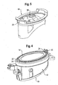
Figur 4 eine perspektivische Ansicht der an das Gehäuse angeformten Dichtung vonFigur 1 , -
Figur 5 eine perspektivische Ansicht des Reflektors vonFigur 1 , -
Figur 6 eine Schnittansicht des Scheinwerfers entlang der Linie VI-VI inFigur 1 , und -
Figur 7 eine Schnittansicht des Scheinwerfers entlang der Linie VII-VII inFigur 1 . - In den Figuren ist ein Teil eines Scheinwerfers dargestellt, wobei
Figur 1 eine Gesamtansicht mit einem Gehäuse 12, einer Dichtung 14, die an das Gehäuse 12 angeformt ist, und einem Reflektor 16 zeigt, der größtenteils in dem Gehäuse 12 aufgenommen ist. - Das im allgemeinen hülsenförmige Kunststoff-Gehäuse 12 (
Figur 3 ) hat ein abgeschrägtes erstes Ende 18 (Figur 6 ), das von einer nicht gezeigten lichtdurchlässigen Scheibe abgedeckt ist, und ein zweites Ende 20 (Figur 6 ). An dem zweiten Ende 20 ist die elliptische, inFigur 2 gezeigte Dichtung 14 angeformt. - Am Ende 20 des Gehäuses 12 sind zwei Vorsprünge 22 mit jeweils einer runden Aussparung 24 vorgesehen, die sich gegenüberliegen. Durch die Aussparungen 24 des Gehäuses 12 können sich zwei Stifte 26 (
Figur 5 ), die Teil des Reflektors 16 sind, erstrecken. Der konkav gewölbte Reflektor 16, der in denFiguren 5 bis 7 gezeigt ist, hat eine Öffnung 28, die eine Lampenfassung (nicht gezeigt) aufnehmen kann. - Der Scheinwerfer wird folgendermaßen zusammengebaut: Die Dichtung 14 wird im In-Mold-Assembly-Verfahren an das Gehäuse 12 angespritzt und fällt anschließend zusammen mit dem Gehäuse 12 in der in
Figur 4 gezeigten Form aus einem nicht gezeigten Spritzwerkzeug. Der separat hergestellte Reflektor 16 wird von (gemäßFigur 4 ) oben in das Gehäuse 12 eingesetzt und die Stifte 26 in die dazu fluchtenden Aussparungen 24 des Gehäuses 12 gesteckt, so daß der Reflektor 16 begrenzt beweglich im Gehäuse 12 aufgenommen ist. Durch die Öffnung 28 des Reflektors 16 wird anschließend die nicht gezeigte, mit einer Spannungsquelle verbundene Lampenfassung mit einem daran angebrachten Leuchtmittel (nicht gezeigt) eingebracht und das Gehäuse 12 am Ende 18 durch eine nicht gezeigte lichtdurchlässige Scheibe abgedeckt. - Der so hergestellte und zusammengebaute Scheinwerfer, der in den
Figuren 1 und4 ,6 und 7 gezeigt ist, erfüllt die Dichtigkeitsanforderungen und ist einfach und schnell herstellbar, insbesondere da die Dichtung 14 an das Gehäuse 12 angeformt ist.
Claims (3)
- Scheinwerfer für ein Fahrzeug, mit
einem Gehäuse (12),
einem Reflektor (16) und
einer Dichtung (14), die zwischen dem Gehäuse (12) und dem Reflektor (16) angeordnet und an das Gehäuse (12) angeformt ist, wobei
am Gehäuse (12) zwei Vorsprünge (22) vorgesehen sind, an denen der Reflektor (16) angreifen kann, ,
dadurch gekennzeichnet, dass sich die Vorsprünge (22) durch die Dichtung (14) erstrecken. - Scheinwerfer nach Anspruch 1, dadurch gekennzeichnet, dass die Dichtung (14) an das Gehäuse (12) angespritzt ist.
- Scheinwerfer nach einem der vorhergehenden Ansprüche, dadurch gekennzeichnet, dass der Reflektor (16) Stifte (26) aufweist und das Gehäuse (12) Aussparungen (24), wobei sich die Stifte (26) im montierten Zustand durch die Aussparungen (24) erstrecken und der Reflektor (16) so begrenzt beweglich im Gehäuse (12) gelagert ist.
Priority Applications (1)
| Application Number | Priority Date | Filing Date | Title |
|---|---|---|---|
| PL07024140T PL1933084T3 (pl) | 2006-12-15 | 2007-12-12 | Reflektor dla pojazdu |
Applications Claiming Priority (1)
| Application Number | Priority Date | Filing Date | Title |
|---|---|---|---|
| DE202006018972U DE202006018972U1 (de) | 2006-12-15 | 2006-12-15 | Scheinwerfer für ein Fahrzeug |
Publications (2)
| Publication Number | Publication Date |
|---|---|
| EP1933084A1 EP1933084A1 (de) | 2008-06-18 |
| EP1933084B1 true EP1933084B1 (de) | 2010-01-27 |
Family
ID=37950355
Family Applications (1)
| Application Number | Title | Priority Date | Filing Date |
|---|---|---|---|
| EP07024140A Not-in-force EP1933084B1 (de) | 2006-12-15 | 2007-12-12 | Scheinwerfer für ein Fahrzeug |
Country Status (5)
| Country | Link |
|---|---|
| EP (1) | EP1933084B1 (de) |
| AT (1) | ATE456767T1 (de) |
| DE (2) | DE202006018972U1 (de) |
| ES (1) | ES2338597T3 (de) |
| PL (1) | PL1933084T3 (de) |
Families Citing this family (1)
| Publication number | Priority date | Publication date | Assignee | Title |
|---|---|---|---|---|
| CN120083937B (zh) * | 2025-05-06 | 2025-08-29 | 浙江屹纬精密技术有限公司 | 汽车大灯灯座及制造方法 |
Family Cites Families (4)
| Publication number | Priority date | Publication date | Assignee | Title |
|---|---|---|---|---|
| DE3542784A1 (de) | 1985-12-04 | 1987-06-11 | Hella Kg Hueck & Co | Scheinwerfer fuer kraftfahrzeuge |
| DE4235289C2 (de) | 1992-10-20 | 1996-08-01 | Teves Gmbh Alfred | Signalleuchte für ein Fahrzeug |
| DE19541217C2 (de) | 1995-11-04 | 1999-10-21 | Sidler Gmbh & Co | Dichtungsanordnung für eine Leuchte |
| ES1046457Y (es) | 2000-06-27 | 2001-05-16 | Fed Signal Vama Sa | Foco direccional. |
-
2006
- 2006-12-15 DE DE202006018972U patent/DE202006018972U1/de not_active Expired - Lifetime
-
2007
- 2007-12-12 ES ES07024140T patent/ES2338597T3/es active Active
- 2007-12-12 DE DE502007002733T patent/DE502007002733D1/de active Active
- 2007-12-12 EP EP07024140A patent/EP1933084B1/de not_active Not-in-force
- 2007-12-12 AT AT07024140T patent/ATE456767T1/de active
- 2007-12-12 PL PL07024140T patent/PL1933084T3/pl unknown
Also Published As
| Publication number | Publication date |
|---|---|
| DE502007002733D1 (de) | 2010-03-18 |
| EP1933084A1 (de) | 2008-06-18 |
| ES2338597T3 (es) | 2010-05-10 |
| PL1933084T3 (pl) | 2010-06-30 |
| DE202006018972U1 (de) | 2007-04-05 |
| ATE456767T1 (de) | 2010-02-15 |
Similar Documents
| Publication | Publication Date | Title |
|---|---|---|
| DE19615026A1 (de) | Befestigungsvorrichtung für einen Scheinwerfer eines Kraftfahrzeuges | |
| DE10004700A1 (de) | Scheinwerfer für Kraftfahrzeuge | |
| EP2450240A1 (de) | Mehrteilige Blendenleiste | |
| EP3727073B1 (de) | Beleuchtetes gurtschloss für eine sicherheitsgurteinrichtung eines kraftfahrzeuges | |
| EP1655174A2 (de) | Fahrzeugleuchtenanordnung | |
| WO2004088352A1 (de) | Sensoranordnung einer enparkhilfe | |
| DE102019209780A1 (de) | Verfahren zum Herstellen einer Blinkereinrichtung mittels eines Spritzgussverfahrens, Blinkereinrichtung, Seitenspiegel sowie Kraftfahrzeug | |
| EP2305518B1 (de) | Vorrichtung für die Befestigung einer Stoßfängerverkleidung | |
| DE102015114238A1 (de) | Anbindungssystem und Verfahren zur Befestigung eines Bauteils an einer Fahrzeugkarosserie | |
| EP3371004B1 (de) | Fahrzeugaussenspiegel mit integrierter signalleuchteneinheit, sowie verfahren zur herstellung eines fahrzeugaussenspiegels mit integrierter signalleuchteneinheit | |
| EP1933084A1 (de) | Scheinwerfer für ein Fahrzeug | |
| DE102021121783A1 (de) | Bauteil für ein Verkehrsmittel, Verkehrsmittel und Verfahren zur Herstellung des Bauteils | |
| EP1657488B1 (de) | Leuchte für Fahrzeuge, vorzugsweise für Kraftfahrzeuge | |
| EP0879735A2 (de) | Leuchte, insbesondere Heckleuchte, für Fahrzeuge, vorzugsweise Kraftfahrzeuge | |
| DE102004025232A1 (de) | Befestigungsvorrichtung für eine Zierleiste | |
| EP0326820B1 (de) | Scheinwerfer für Fahrzeuge, insbesondere Kraftfahrzeuge | |
| DE102024138757B3 (de) | Beleuchtungsvorrichtung für ein Kraftfahrzeug sowie Verfahren zum Reparieren einer Beleuchtungsvorrichtung | |
| DE102011013843A1 (de) | Spritzgießverfahren zum Herstellen eines Kunststoffbauteils | |
| DE10261772A1 (de) | Leiterbahn aus flexiblem Material, Baueinheit mit einer solchen flexiblen Leiterbahn und Verfahren zur Herstellung einer solchen Leiterbahn | |
| DE102004033758A1 (de) | Bremsleuchte | |
| DE102023211821B4 (de) | Beleuchtungsvorrichtung für ein Kraftfahrzeug sowie Kraftfahrzeug mit einer solchen Beleuchtungsvorrichtung | |
| DE102015206902A1 (de) | Verfahren zur Herstellung einer Längsträgerverkleidungen sowie Längsträgerverkleidung | |
| DE2832395A1 (de) | Scheinwerfer fuer kraftfahrzeuge | |
| DE102016213317A1 (de) | Lichtdurchlässiges Leuchtengehäuseteil | |
| DE202025101259U1 (de) | Kunststoffgehäuse einer Beleuchtungseinrichtung und Beleuchtungseinrichtung mit einem solchen Kunststoffgehäuse |
Legal Events
| Date | Code | Title | Description |
|---|---|---|---|
| PUAI | Public reference made under article 153(3) epc to a published international application that has entered the european phase |
Free format text: ORIGINAL CODE: 0009012 |
|
| AK | Designated contracting states |
Kind code of ref document: A1 Designated state(s): AT BE BG CH CY CZ DE DK EE ES FI FR GB GR HU IE IS IT LI LT LU LV MC MT NL PL PT RO SE SI SK TR |
|
| AX | Request for extension of the european patent |
Extension state: AL BA HR MK RS |
|
| 17P | Request for examination filed |
Effective date: 20081014 |
|
| 17Q | First examination report despatched |
Effective date: 20081114 |
|
| AKX | Designation fees paid |
Designated state(s): AT BE BG CH CY CZ DE DK EE ES FI FR GB GR HU IE IS IT LI LT LU LV MC MT NL PL PT RO SE SI SK TR |
|
| GRAP | Despatch of communication of intention to grant a patent |
Free format text: ORIGINAL CODE: EPIDOSNIGR1 |
|
| GRAS | Grant fee paid |
Free format text: ORIGINAL CODE: EPIDOSNIGR3 |
|
| GRAA | (expected) grant |
Free format text: ORIGINAL CODE: 0009210 |
|
| AK | Designated contracting states |
Kind code of ref document: B1 Designated state(s): AT BE BG CH CY CZ DE DK EE ES FI FR GB GR HU IE IS IT LI LT LU LV MC MT NL PL PT RO SE SI SK TR |
|
| REG | Reference to a national code |
Ref country code: GB Ref legal event code: FG4D Free format text: NOT ENGLISH |
|
| REG | Reference to a national code |
Ref country code: CH Ref legal event code: EP |
|
| REG | Reference to a national code |
Ref country code: IE Ref legal event code: FG4D |
|
| REF | Corresponds to: |
Ref document number: 502007002733 Country of ref document: DE Date of ref document: 20100318 Kind code of ref document: P |
|
| REG | Reference to a national code |
Ref country code: ES Ref legal event code: FG2A Ref document number: 2338597 Country of ref document: ES Kind code of ref document: T3 |
|
| REG | Reference to a national code |
Ref country code: SE Ref legal event code: TRGR |
|
| REG | Reference to a national code |
Ref country code: NL Ref legal event code: VDEP Effective date: 20100127 |
|
| LTIE | Lt: invalidation of european patent or patent extension |
Effective date: 20100127 |
|
| PG25 | Lapsed in a contracting state [announced via postgrant information from national office to epo] |
Ref country code: LT Free format text: LAPSE BECAUSE OF FAILURE TO SUBMIT A TRANSLATION OF THE DESCRIPTION OR TO PAY THE FEE WITHIN THE PRESCRIBED TIME-LIMIT Effective date: 20100127 Ref country code: NL Free format text: LAPSE BECAUSE OF FAILURE TO SUBMIT A TRANSLATION OF THE DESCRIPTION OR TO PAY THE FEE WITHIN THE PRESCRIBED TIME-LIMIT Effective date: 20100127 Ref country code: IS Free format text: LAPSE BECAUSE OF FAILURE TO SUBMIT A TRANSLATION OF THE DESCRIPTION OR TO PAY THE FEE WITHIN THE PRESCRIBED TIME-LIMIT Effective date: 20100527 Ref country code: PT Free format text: LAPSE BECAUSE OF FAILURE TO SUBMIT A TRANSLATION OF THE DESCRIPTION OR TO PAY THE FEE WITHIN THE PRESCRIBED TIME-LIMIT Effective date: 20100527 |
|
| REG | Reference to a national code |
Ref country code: IE Ref legal event code: FD4D |
|
| REG | Reference to a national code |
Ref country code: HU Ref legal event code: AG4A Ref document number: E007920 Country of ref document: HU |
|
| PG25 | Lapsed in a contracting state [announced via postgrant information from national office to epo] |
Ref country code: LV Free format text: LAPSE BECAUSE OF FAILURE TO SUBMIT A TRANSLATION OF THE DESCRIPTION OR TO PAY THE FEE WITHIN THE PRESCRIBED TIME-LIMIT Effective date: 20100127 Ref country code: FI Free format text: LAPSE BECAUSE OF FAILURE TO SUBMIT A TRANSLATION OF THE DESCRIPTION OR TO PAY THE FEE WITHIN THE PRESCRIBED TIME-LIMIT Effective date: 20100127 Ref country code: SI Free format text: LAPSE BECAUSE OF FAILURE TO SUBMIT A TRANSLATION OF THE DESCRIPTION OR TO PAY THE FEE WITHIN THE PRESCRIBED TIME-LIMIT Effective date: 20100127 |
|
| PG25 | Lapsed in a contracting state [announced via postgrant information from national office to epo] |
Ref country code: EE Free format text: LAPSE BECAUSE OF FAILURE TO SUBMIT A TRANSLATION OF THE DESCRIPTION OR TO PAY THE FEE WITHIN THE PRESCRIBED TIME-LIMIT Effective date: 20100127 Ref country code: RO Free format text: LAPSE BECAUSE OF FAILURE TO SUBMIT A TRANSLATION OF THE DESCRIPTION OR TO PAY THE FEE WITHIN THE PRESCRIBED TIME-LIMIT Effective date: 20100127 Ref country code: GR Free format text: LAPSE BECAUSE OF FAILURE TO SUBMIT A TRANSLATION OF THE DESCRIPTION OR TO PAY THE FEE WITHIN THE PRESCRIBED TIME-LIMIT Effective date: 20100428 Ref country code: IE Free format text: LAPSE BECAUSE OF FAILURE TO SUBMIT A TRANSLATION OF THE DESCRIPTION OR TO PAY THE FEE WITHIN THE PRESCRIBED TIME-LIMIT Effective date: 20100127 Ref country code: CY Free format text: LAPSE BECAUSE OF FAILURE TO SUBMIT A TRANSLATION OF THE DESCRIPTION OR TO PAY THE FEE WITHIN THE PRESCRIBED TIME-LIMIT Effective date: 20100127 |
|
| PG25 | Lapsed in a contracting state [announced via postgrant information from national office to epo] |
Ref country code: SK Free format text: LAPSE BECAUSE OF FAILURE TO SUBMIT A TRANSLATION OF THE DESCRIPTION OR TO PAY THE FEE WITHIN THE PRESCRIBED TIME-LIMIT Effective date: 20100127 Ref country code: BG Free format text: LAPSE BECAUSE OF FAILURE TO SUBMIT A TRANSLATION OF THE DESCRIPTION OR TO PAY THE FEE WITHIN THE PRESCRIBED TIME-LIMIT Effective date: 20100427 |
|
| PLBE | No opposition filed within time limit |
Free format text: ORIGINAL CODE: 0009261 |
|
| STAA | Information on the status of an ep patent application or granted ep patent |
Free format text: STATUS: NO OPPOSITION FILED WITHIN TIME LIMIT |
|
| 26N | No opposition filed |
Effective date: 20101028 |
|
| PG25 | Lapsed in a contracting state [announced via postgrant information from national office to epo] |
Ref country code: DK Free format text: LAPSE BECAUSE OF FAILURE TO SUBMIT A TRANSLATION OF THE DESCRIPTION OR TO PAY THE FEE WITHIN THE PRESCRIBED TIME-LIMIT Effective date: 20100127 |
|
| PGFP | Annual fee paid to national office [announced via postgrant information from national office to epo] |
Ref country code: PL Payment date: 20101123 Year of fee payment: 4 |
|
| PGFP | Annual fee paid to national office [announced via postgrant information from national office to epo] |
Ref country code: TR Payment date: 20101125 Year of fee payment: 4 |
|
| BERE | Be: lapsed |
Owner name: TRW AUTOMOTIVE ELECTRONICS & COMPONENTS G.M.B.H. Effective date: 20101231 |
|
| PG25 | Lapsed in a contracting state [announced via postgrant information from national office to epo] |
Ref country code: MC Free format text: LAPSE BECAUSE OF NON-PAYMENT OF DUE FEES Effective date: 20101231 |
|
| PG25 | Lapsed in a contracting state [announced via postgrant information from national office to epo] |
Ref country code: BE Free format text: LAPSE BECAUSE OF NON-PAYMENT OF DUE FEES Effective date: 20101231 |
|
| PG25 | Lapsed in a contracting state [announced via postgrant information from national office to epo] |
Ref country code: MT Free format text: LAPSE BECAUSE OF FAILURE TO SUBMIT A TRANSLATION OF THE DESCRIPTION OR TO PAY THE FEE WITHIN THE PRESCRIBED TIME-LIMIT Effective date: 20100127 Ref country code: IT Free format text: LAPSE BECAUSE OF NON-PAYMENT OF DUE FEES Effective date: 20101212 |
|
| PGFP | Annual fee paid to national office [announced via postgrant information from national office to epo] |
Ref country code: IT Payment date: 20101231 Year of fee payment: 4 |
|
| PGFP | Annual fee paid to national office [announced via postgrant information from national office to epo] |
Ref country code: HU Payment date: 20111125 Year of fee payment: 5 Ref country code: CZ Payment date: 20111129 Year of fee payment: 5 Ref country code: FR Payment date: 20120104 Year of fee payment: 5 Ref country code: ES Payment date: 20111226 Year of fee payment: 5 Ref country code: SE Payment date: 20111229 Year of fee payment: 5 |
|
| REG | Reference to a national code |
Ref country code: CH Ref legal event code: PL |
|
| PG25 | Lapsed in a contracting state [announced via postgrant information from national office to epo] |
Ref country code: LU Free format text: LAPSE BECAUSE OF NON-PAYMENT OF DUE FEES Effective date: 20101212 |
|
| PG25 | Lapsed in a contracting state [announced via postgrant information from national office to epo] |
Ref country code: CH Free format text: LAPSE BECAUSE OF NON-PAYMENT OF DUE FEES Effective date: 20111231 Ref country code: LI Free format text: LAPSE BECAUSE OF NON-PAYMENT OF DUE FEES Effective date: 20111231 |
|
| PGFP | Annual fee paid to national office [announced via postgrant information from national office to epo] |
Ref country code: DE Payment date: 20121231 Year of fee payment: 6 |
|
| PG25 | Lapsed in a contracting state [announced via postgrant information from national office to epo] |
Ref country code: CZ Free format text: LAPSE BECAUSE OF NON-PAYMENT OF DUE FEES Effective date: 20121212 Ref country code: SE Free format text: LAPSE BECAUSE OF NON-PAYMENT OF DUE FEES Effective date: 20121213 |
|
| GBPC | Gb: european patent ceased through non-payment of renewal fee |
Effective date: 20121212 |
|
| REG | Reference to a national code |
Ref country code: FR Ref legal event code: ST Effective date: 20130830 |
|
| PG25 | Lapsed in a contracting state [announced via postgrant information from national office to epo] |
Ref country code: HU Free format text: LAPSE BECAUSE OF NON-PAYMENT OF DUE FEES Effective date: 20121213 |
|
| PG25 | Lapsed in a contracting state [announced via postgrant information from national office to epo] |
Ref country code: GB Free format text: LAPSE BECAUSE OF NON-PAYMENT OF DUE FEES Effective date: 20121212 Ref country code: FR Free format text: LAPSE BECAUSE OF NON-PAYMENT OF DUE FEES Effective date: 20130102 |
|
| PG25 | Lapsed in a contracting state [announced via postgrant information from national office to epo] |
Ref country code: IT Free format text: LAPSE BECAUSE OF NON-PAYMENT OF DUE FEES Effective date: 20121212 |
|
| REG | Reference to a national code |
Ref country code: AT Ref legal event code: MM01 Ref document number: 456767 Country of ref document: AT Kind code of ref document: T Effective date: 20121212 |
|
| PG25 | Lapsed in a contracting state [announced via postgrant information from national office to epo] |
Ref country code: PL Free format text: LAPSE BECAUSE OF NON-PAYMENT OF DUE FEES Effective date: 20121212 |
|
| REG | Reference to a national code |
Ref country code: ES Ref legal event code: FD2A Effective date: 20140306 |
|
| PG25 | Lapsed in a contracting state [announced via postgrant information from national office to epo] |
Ref country code: TR Free format text: LAPSE BECAUSE OF NON-PAYMENT OF DUE FEES Effective date: 20121212 Ref country code: AT Free format text: LAPSE BECAUSE OF NON-PAYMENT OF DUE FEES Effective date: 20121212 Ref country code: ES Free format text: LAPSE BECAUSE OF NON-PAYMENT OF DUE FEES Effective date: 20121213 |
|
| REG | Reference to a national code |
Ref country code: DE Ref legal event code: R119 Ref document number: 502007002733 Country of ref document: DE |
|
| REG | Reference to a national code |
Ref country code: DE Ref legal event code: R119 Ref document number: 502007002733 Country of ref document: DE Effective date: 20140701 |
|
| PG25 | Lapsed in a contracting state [announced via postgrant information from national office to epo] |
Ref country code: DE Free format text: LAPSE BECAUSE OF NON-PAYMENT OF DUE FEES Effective date: 20140701 |