EP1933471A2 - Équipement utilisateur de système de communications mobile dans un système de communications mobile, son programme de commande, et procédé de commande de la puissance de transmission dans un système de communications mobile - Google Patents
Équipement utilisateur de système de communications mobile dans un système de communications mobile, son programme de commande, et procédé de commande de la puissance de transmission dans un système de communications mobile Download PDFInfo
- Publication number
- EP1933471A2 EP1933471A2 EP07023828A EP07023828A EP1933471A2 EP 1933471 A2 EP1933471 A2 EP 1933471A2 EP 07023828 A EP07023828 A EP 07023828A EP 07023828 A EP07023828 A EP 07023828A EP 1933471 A2 EP1933471 A2 EP 1933471A2
- Authority
- EP
- European Patent Office
- Prior art keywords
- channel
- transmission power
- reception quality
- user equipment
- common channel
- Prior art date
- Legal status (The legal status is an assumption and is not a legal conclusion. Google has not performed a legal analysis and makes no representation as to the accuracy of the status listed.)
- Withdrawn
Links
Images

Classifications
-
- H—ELECTRICITY
- H04—ELECTRIC COMMUNICATION TECHNIQUE
- H04W—WIRELESS COMMUNICATION NETWORKS
- H04W52/00—Power management, e.g. Transmission Power Control [TPC] or power classes
- H04W52/04—Transmission power control [TPC]
- H04W52/18—TPC being performed according to specific parameters
- H04W52/24—TPC being performed according to specific parameters using SIR [Signal to Interference Ratio] or other wireless path parameters
- H04W52/241—TPC being performed according to specific parameters using SIR [Signal to Interference Ratio] or other wireless path parameters taking into account channel quality metrics, e.g. SIR, SNR, CIR or Eb/lo
-
- H—ELECTRICITY
- H04—ELECTRIC COMMUNICATION TECHNIQUE
- H04W—WIRELESS COMMUNICATION NETWORKS
- H04W52/00—Power management, e.g. Transmission Power Control [TPC] or power classes
- H04W52/04—Transmission power control [TPC]
- H04W52/06—TPC algorithms
- H04W52/12—Outer and inner loops
-
- H—ELECTRICITY
- H04—ELECTRIC COMMUNICATION TECHNIQUE
- H04W—WIRELESS COMMUNICATION NETWORKS
- H04W52/00—Power management, e.g. Transmission Power Control [TPC] or power classes
- H04W52/04—Transmission power control [TPC]
- H04W52/18—TPC being performed according to specific parameters
- H04W52/28—TPC being performed according to specific parameters using user profile, e.g. mobile speed, priority or network state, e.g. standby, idle or non-transmission
- H04W52/287—TPC being performed according to specific parameters using user profile, e.g. mobile speed, priority or network state, e.g. standby, idle or non-transmission when the channel is in stand-by
Definitions
- the present invention relates to a mobile communication system for providing communication services to user equipments, the user equipment in the mobile communication system, a control program thereof, and a transmission power control method in the mobile communication system.
- W-CDMA Wideband-Code Division Multiple Access
- transmission power control is performed for maintaining a communication quality to a predetermined level.
- closed-loop transmission power control having a double-loop structure consisting of inner loop control and outer loop control may be performed as the transmission power control.
- FIG. 3 is a schematic diagram showing a concept of the closed-loop transmission power control having the double-loop structure.
- an instruction for causing a transmission power to increase or decrease is issued with respect to an opposite base station so that a Signal to Interference Ratio of a received radio signal (received SIR) in a user equipment (UE) matches a received SIR to be targeted (target SIR).
- the target SIR in the inner loop control is caused to increase or decrease so that a received Block Error Rate (received BLER) of user data in the user equipment matches a received BLER to be targeted (target BLER).
- a state occurs in which only a DCCH is set and a DTCH is not set.
- a state occurs in which Radio Resource Control (RRC) has been established in a connection procedure performed between the user equipment and the base station.
- RRC Radio Resource Control
- the DCCH has been set as a dedicated physical channel, and the DTCH has not been set in this state.
- the user equipment performs the Blind transport format detection with respect to the DCCH.
- Radio Access Bearer (RAB) is established.
- the DTCH is set and the connection procedure is completed.
- the target SIR in the outer loop control since the target SIR is not changed, a power more than or equal to a certain level is not requested even though a reception quality has deteriorated, and thereby a situation occurs in which data transmission and reception are failed. Conversely, an excessive transmission power is requested even though the reception quality has been improved, and thereby a situation occurs in which power consumption is increased or interference to another communication is caused.
- the target SIR is determined based on the received data error rate of the pilot signal in the dedicated physical control channel, since the pilot signal in the dedicated physical control channel (DPCCH) is discretely transmitted and an information amount is limited, the target SIR to be set may not be an appropriate value.
- DPCCH dedicated physical control channel
- a method of updating the target SIR in the StandAlone-DCCH period by the outer loop control a method of transmitting a signal attached only with the CRC from the base station to the user equipment and measuring the BLER of a dedicated channel even if there is no control information is conceivable.
- the signal is transmitted even though there is no control information, which causes unnecessary power consumption, and also, although a CRC check has been completed at one time, the number of CRC checks increases twice in the Blind transport format detection under a condition of the StandAlone-DCCH.
- the present invention is a mobile communication system, including a base station having a predetermined communicable area and a user equipment which communicates with the above described base station if the user equipment belongs to the above described communicable area, the above described base station and the above described user equipment communicating with each other via a common channel commonly used by multiple user equipments (for example, a CPICH in a W-CDMA wireless system) and a dedicated channel individually set for each user equipment (for example, a DCH in the W-CDMA wireless system), the above described user equipment performing transmission power control for causing a transmission power in the above described base station to change based on a reception quality of a data transfer channel in the dedicated channel (for example, a DTCH in the W-CDMA wireless system), and the above described user equipment includes common channel reception quality measurement means which measures a reception quality of a channel in which a predetermined code is continuously transmitted, among the above described common channel (for example, a common channel quality measurement unit 22 of FIG.
- stand-alone state detection means which detects whether or not there is a stand-alone communication state in which the data transfer channel in the dedicated channel has not been set and control information is transmitted and received only via a control channel in the dedicated channel (for example, a DCCH in the W-CDMA wireless system) (for example, a control unit 24 of FIG. 1 which executes a flowchart shown in FIG. 2 ), and stand-alone-period transmission power control means which, if the above described stand-alone communication state has been detected by the above described stand-alone state detection means, performs transmission power control corresponding to the common channel (for example, transmission power control corresponding to the common channel of FIG.
- a control channel in the dedicated channel for example, a DCCH in the W-CDMA wireless system
- stand-alone-period transmission power control means which, if the above described stand-alone communication state has been detected by the above described stand-alone state detection means, performs transmission power control corresponding to the common channel (for example, transmission power control corresponding
- the transmission power in the above described base station for causing the transmission power in the above described base station to change based on the reception quality of the common channel measured by the above described common channel reception quality measurement means (for example, the control unit 24 of FIG. 1 which executes the flowchart shown in FIG. 2 ), and that the above described base station changes the transmission power of the dedicated channel with respect to the above described user equipment, depending on the transmission power control performed by the above described user equipment.
- the above described common channel reception quality measurement means for example, the control unit 24 of FIG. 1 which executes the flowchart shown in FIG. 2
- the present invention is a user equipment in a mobile communication system, the above described mobile communication system including a base station having a predetermined communicable area and the user equipment which communicates with the above described base station if the user equipment belongs to the above described communicable area, the above described base station and the above described user equipment communicating with each other via a common channel commonly used by multiple user equipments and a dedicated channel individually set for each user equipment, the above described user equipment performing transmission power control for causing a transmission power in the above described base station to change based on a reception quality of a data transfer channel in the dedicated channel, and the above described user equipment includes common channel reception quality measurement means which measures a reception quality of a channel in which a predetermined code is continuously transmitted, among the above described common channel, stand-alone state detection means which detects whether or not there is a stand-alone communication state in which the data transfer channel in the dedicated channel has not been set and control information is transmitted and received only via a control channel in the dedicated channel, and stand-alone-period transmission power control
- the present invention is a control program of a user equipment in a mobile communication system, the above described mobile communication system including a base station having a predetermined communicable area and the user equipment which communicates with the above described base station if the user equipment belongs to the above described communicable area, the above described base station and the above described user equipment communicating with each other via a common channel commonly used by multiple user equipments and a dedicated channel individually set for each user equipment, the above described user equipment performing transmission power control for causing a transmission power in the above described base station to change based on a reception quality of a data transfer channel in the dedicated channel, and the above described control program causes a computer to realize a common channel reception quality measurement function of measuring a reception quality of a channel in which a predetermined code is continuously transmitted, among the above described common channel, a stand-alone state detection function of detecting whether or not there is a stand-alone communication state in which the data transfer channel in the dedicated channel has not been set and control information is transmitted and received only via a control channel in the dedicated
- the present invention is a transmission power control method in a mobile communication system, the above described mobile communication system including a base station having a predetermined communicable area and a user equipment which communicates with the above described base station if the user equipment belongs to the above described communicable area, the above described base station and the above described user equipment communicating with each other via a common channel commonly used by multiple user equipments and a dedicated channel individually set for each user equipment, the above described user equipment performing transmission power control for causing a transmission power in the above described base station to change based on a reception quality of a data transfer channel in the dedicated channel, and the above described transmission power control method includes, in the above described user equipment, a common channel reception quality measurement step of measuring a reception quality of a channel in which a predetermined code is continuously transmitted, among the above described common channel, a stand-alone state detection step of detecting whether or not there is a stand-alone communication state in which the data transfer channel in the dedicated channel has not been set and control information is transmitted and received only via a control channel
- the reception quality of the common channel is measured, and if the stand-alone communication state has occurred, the transmission power control corresponding to the common channel for causing the transmission power in the base station to change depending on the reception quality of the channel in which the predetermined code is continuously transmitted, among the common channel, is performed.
- the above described stand-alone state detection means detects the above described stand-alone communication state, in a state in which Radio Resource Control has been established, if Radio Access Bearer has not been established.
- RRC Radio Resource Control
- RAB Radio Access Bearer
- Radio Access Bearer Setup information (Radio Bearer Setup signal) transmitted from the base station in a connection procedure has been received.
- the above described common channel reception quality measurement means measures a reception quality of a common pilot channel as the above described common channel.
- This common pilot channel is always broadcasted to each user equipment and used in the user equipment to measure a time base of the base station, and code spreading has not been performed therein.
- the common pilot channel can be easily acquired in the user equipment. Therefore, if the dedicated channel becomes the stand-alone communication state and a reception quality of the dedicated channel cannot be measured, it is possible to use the common pilot channel, which can be constantly set as a basis for showing a reception state, to adequately estimate the reception quality of the dedicated channel.
- the above described common channel reception quality measurement means measures a received RSCP as the reception quality of the above described common channel.
- the above described common channel reception quality measurement means measures a received Ec/NO as the reception quality of the above described common channel.
- the above described common channel reception quality measurement means measures a received bit error rate as the reception quality of the above described common channel.
- the above described common channel reception quality measurement means measures a received SIR as the reception quality of the above described common channel.
- the present invention further includes common channel reception quality storage means which stores a result of the measurement by the above described common channel reception quality measurement means when the above described stand-alone communication state has been detected, and the above described stand-alone-period transmission power control means compares the measurement result stored by the common channel reception quality storage means with a measurement result which is subsequently measured by the above described common channel reception quality measurement means, and performs the transmission power control based on a result of the comparison.
- the present invention even if the Blind transport format detection is used in the stand-alone communication state, it is possible to perform the transmission power control in accordance with the reception status of the user equipment, enabling the adequate transmission power control depending on the change in the communication status.
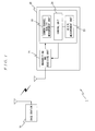
- FIG. 1 is a schematic diagram showing a base station and a user equipment in a W-CDMA wireless system 1 according to the present invention.
- the W-CDMA wireless system 1 includes a base station 10 and a user equipment 20.
- the base station 10 is provided with a base station function in a mobile communication system using W-CDMA.
- the base station 10 establishes communication based on the W-CDMA with the user equipment 20 in a communicable area of the base station 10, and communicates with the user equipment 20 via physical channels including a common pilot channel (CPICH), a common control physical channel (CCPCH) and a dedicated physical channel (DPCH).
- CPICH common pilot channel
- CPCH common control physical channel
- DPCH dedicated physical channel
- the common pilot channel is a channel for continuously transmitting a scrambling code (PN code) of the base station 10, and this channel is broadcasted to all user equipments 20.
- PN code scrambling code
- the common control physical channel is a channel for transmitting BCH information, control information such as a paging signal, or low rate user data.
- One dedicated physical channel is assigned to each user equipment 20, and the dedicated physical channel is a channel for transmitting and receiving the user data.
- a DCH Dedicated CHannel
- a DCCH Dedicated Control CHannel
- a DTCH Dedicated Traffic CHannel
- the base station 10 transmits and receives the user data with respect to the user equipment 20 via the DTCH, and transmits and receives the control information via the DCCH.
- the user equipment 20 is provided with a transmitting and receiving unit 21, a common channel quality measurement unit 22, a BER (Bit Error Rate) measurement unit 23 and a control unit 24. It should be noted that the user equipment 20 is provided with a CPU (Central Processing Unit), a main memory, a nonvolatile storage device and a display device as hardware, and the CPU reads various programs stored in the nonvolatile storage device and executes the programs to realize various functions.
- a CPU Central Processing Unit
- the transmitting and receiving unit 21 performs frequency conversion or a demodulation process and data decomposition based on the W-CDMA with respect to a radio signal received via an antenna, and outputs a result of the process to the control unit 24. Also, the transmitting and receiving unit 21 performs data multiplexing or a modulation process and the frequency conversion based on the W-CDMA with respect to a signal inputted from the control unit 24, and transmits a result of the process via the antenna.
- the common channel quality measurement unit 22 measures a reception quality of a common channel (common pilot channel) in the communication between the base station 10 and the user equipment 20, and outputs a result of the measurement to the control unit 24.
- the common pilot channel is used in the user equipment 20 to measure a time base of the base station 10, and code spreading has not been performed therein. Thus, the common pilot channel can be easily acquired in the user equipment 20.
- the reception quality measured by the common channel quality measurement unit 22 can be, for example, an RSCP (Received Signal Code Power), a received Ec/NO (desired signal-to-noise power ratio), a received bit error rate (BER), an SIR or the like.
- RSCP Receiveived Signal Code Power
- Ec/NO received signal-to-noise power ratio
- BER received bit error rate
- the BER measurement unit 23 measures the BER of the dedicated physical channel, and outputs a result of the measurement to the control unit 24.
- the control unit 24 controls the entire user equipment 20, measures a received SIR of the dedicated physical channel based on the BER measurement result inputted by the BER measurement unit 23, and compares a result of the measurement with a threshold set for transmission power control in a non-StandAlone-DCCH state (hereinafter referred to as "normal transmission power control"). If the received SIR which has been measured is higher than the threshold, the control unit 24 transmits the control information (TPC bits) for causing a transmission power in the base station 10 to decrease by a set value. Moreover, if the received SIR which has been measured is lower than the threshold, the control unit 24 transmits the control information for causing the transmission power in the base station 10 to increase by the set value.
- TPC bits control information for causing a transmission power in the base station 10 to decrease by a set value.
- the control unit 24 detects whether or not a StandAlone-DCCH state (stand-alone communication state) has occurred in which the DTCH in the dedicated physical channel has not been set and only the control information via the DCCH is transmitted and received.
- a StandAlone-DCCH state stand-alone communication state
- RRC Radio Resource Control
- RAB Radio Access Bearer
- the control unit 24 detects the stand-alone communication state. Whether or not the Radio Access Bearer has been established can be determined based on whether or not Radio Access Bearer Setup information (Radio Bearer Setup signal) transmitted from the base station 10 to the user equipment 20 in the connection procedure has been received.
- Radio Access Bearer Setup information Radio Bearer Setup signal
- the control unit 24 executes a transmission power control process for the StandAlone-DCCH state which will be described later, and compares the reception quality of the common channel inputted by the common channel quality measurement unit 22 with a threshold set for the transmission power control using the reception quality of the common channel (hereinafter referred to as "common channel threshold") (hereinafter, the transmission power control process for the StandAlone-DCCH state will be referred to as "transmission power control corresponding to the common channel"). If the reception quality of the common channel is higher than the common channel threshold, the control unit 24 transmits the control information (TPC bits) for causing the transmission power in the base station 10 to decrease by the set value. Moreover, if the reception quality of the common channel is lower than the common channel threshold, the control unit 24 transmits the control information for causing the transmission power in the base station 10 to increase by the set value.
- TPC bits control information for causing the transmission power in the base station 10 to increase by the set value.
- the control unit 24 transmits the control information in accordance with the normal transmission power control to the base station 10, and if there is the StandAlone-DCCH state, the control unit 24 transmits the control information in accordance with the transmission power control corresponding to the common channel, to the base station 10.
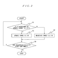
- FIG. 2 is a flowchart showing the transmission power control process corresponding to the common channel executed by the control unit 24.
- the transmission power control process corresponding to the common channel is started correspondingly to the detection of the StandAlone-DCCH state by the control unit 24.
- control unit 24 determines whether or not it is necessary to change a target SIR, that is, determines a height of the reception quality of the common channel with respect to the common channel threshold (step S1).
- step S2 if it is determined that it is not necessary to change the target SIR (for example, the reception quality of the common channel matches the common channel threshold), the current target SIR is maintained (step S2).
- step S1 if it is determined that it is necessary to change the target SIR (for example, the reception quality of the common channel is higher or lower than the common channel threshold), the control unit 24 updates the current target SIR depending on a relationship between the common channel threshold and the reception quality of the common channel, and causes the target SIR to increase or decrease (step S3).
- the target SIR for example, the reception quality of the common channel is higher or lower than the common channel threshold
- step S4 determines whether or not the StandAlone-DCCH state has continued. If it is determined that the StandAlone-DCCH state has continued, the process proceeds to step S1, and if it is determined that the StandAlone-DCCH state has not continued, the transmission power control process corresponding to the common channel is completed.
- a normal transmission power control process (the transmission power control process based on a reception quality of the dedicated physical channel) is performed, and if there is the StandAlone-DCCH state, the transmission power control process corresponding to the common channel (the transmission power control process based on the reception quality of the common channel) is performed.
- the reception quality of the common channel is measured, and if the StandAlone-DCCH state has occurred, the transmission power control corresponding to the common channel is performed in which the target SIR is determined depending on the reception quality of the common channel.
- the common pilot channel when used as this embodiment, since the code spreading has not been performed in the common pilot channel, the common pilot channel can be easily acquired in the user equipment 20 and thereby can be an appropriate basis for determining the reception quality.
- the reception quality of the common channel is measured, and the target SIR is determined based on the reception quality at each timing.
- a common channel reception quality storage unit which stores the reception quality of the common channel when the StandAlone-DCCH state has occurred (that is, at the time when a state has occurred in which the DTCH has not been set) can be provided in the control unit 24, and the control unit 24 can compare the reception quality of the common channel inputted by the common channel quality measurement unit 22 with the reception quality stored by the common channel reception quality storage unit, and determine the target SIR depending on a difference between them.
- the control unit 24 as a method of updating the target SIR based on the reception quality of the common channel, it is possible to estimate the received SIR of the DCCH in consideration of an Ec/NO and a path loss of the CPICH as well as a received RSCP and an SF of the dedicated channel (DCH), thereby determine a divergence from the target SIR, and then change the target SIR if the divergence is large, and maintain the target SIR if the divergence is small.
- a method of estimating the received SIR of the DCCH it is possible to use a logical conversion method or a method of estimating the received SIR of the DCCH based on an experimental value or an empirical value.
- the target SIR is set to the target SIR-1 dB;
- the target SIR is set to the target SIR +1 dB;
Landscapes
- Engineering & Computer Science (AREA)
- Computer Networks & Wireless Communication (AREA)
- Signal Processing (AREA)
- Quality & Reliability (AREA)
- Mobile Radio Communication Systems (AREA)
Applications Claiming Priority (2)
| Application Number | Priority Date | Filing Date | Title |
|---|---|---|---|
| JP2006333352 | 2006-12-11 | ||
| JP2007304652A JP4981636B2 (ja) | 2006-12-11 | 2007-11-26 | 移動体通信システム、移動体通信システムにおける移動端末、その制御プログラムおよび移動体通信システムにおける送信電力制御方法 |
Publications (2)
| Publication Number | Publication Date |
|---|---|
| EP1933471A2 true EP1933471A2 (fr) | 2008-06-18 |
| EP1933471A3 EP1933471A3 (fr) | 2011-02-16 |
Family
ID=39263064
Family Applications (1)
| Application Number | Title | Priority Date | Filing Date |
|---|---|---|---|
| EP07023828A Withdrawn EP1933471A3 (fr) | 2006-12-11 | 2007-12-10 | Équipement utilisateur de système de communications mobile dans un système de communications mobile, son programme de commande, et procédé de commande de la puissance de transmission dans un système de communications mobile |
Country Status (2)
| Country | Link |
|---|---|
| US (1) | US7813756B2 (fr) |
| EP (1) | EP1933471A3 (fr) |
Families Citing this family (2)
| Publication number | Priority date | Publication date | Assignee | Title |
|---|---|---|---|---|
| US8718567B2 (en) * | 2010-03-25 | 2014-05-06 | Apple Inc. | Methods for calibrating radio-frequency receivers using code division multiple access test equipment |
| RU2660923C1 (ru) * | 2014-12-12 | 2018-07-11 | Телефонактиеболагет Лм Эрикссон (Пабл) | Управление радиоканалом в комбинированной соте |
Family Cites Families (9)
| Publication number | Priority date | Publication date | Assignee | Title |
|---|---|---|---|---|
| GB2328584B (en) * | 1997-08-22 | 2002-05-29 | Nokia Mobile Phones Ltd | Switching control method and apparatus for wireless telecommunications |
| KR100605978B1 (ko) * | 1999-05-29 | 2006-07-28 | 삼성전자주식회사 | 부호분할다중접속 이동통신시스템의 불연속 전송모드에서 연속적인 외부순환 전력제어를 위한 송수신 장치 및 방법 |
| KR100735402B1 (ko) * | 2000-11-07 | 2007-07-04 | 삼성전자주식회사 | 비동기 이동통신시스템에서 하향 공유 채널에 사용하는 송신 형식 결합 지시기의 전송 장치 및 방법 |
| JP2003318818A (ja) | 2002-04-23 | 2003-11-07 | Nec Corp | 携帯電話装置とその送信電力制御方法 |
| JP2004274117A (ja) | 2003-03-05 | 2004-09-30 | Mitsubishi Electric Corp | 通信装置及び送信電力制御方法 |
| JP2005005762A (ja) | 2003-06-09 | 2005-01-06 | Fujitsu Ltd | 送信電力制御方法及び装置 |
| JP3866275B2 (ja) * | 2004-02-13 | 2007-01-10 | 三菱電機株式会社 | 通信システム、通信装置、受信機並びに通信方法 |
| JP4619192B2 (ja) | 2005-05-10 | 2011-01-26 | 株式会社エヌ・ティ・ティ・ドコモ | 送信電力制御方法および装置 |
| KR20070073059A (ko) * | 2006-01-03 | 2007-07-10 | 삼성전자주식회사 | 이동통신 시스템의 전력 제어 장치 및 방법 |
-
2007
- 2007-12-10 EP EP07023828A patent/EP1933471A3/fr not_active Withdrawn
- 2007-12-10 US US11/953,421 patent/US7813756B2/en not_active Expired - Fee Related
Also Published As
| Publication number | Publication date |
|---|---|
| EP1933471A3 (fr) | 2011-02-16 |
| US20080176574A1 (en) | 2008-07-24 |
| US7813756B2 (en) | 2010-10-12 |
Similar Documents
| Publication | Publication Date | Title |
|---|---|---|
| US7069035B2 (en) | Method and apparatus for power control in a communication system | |
| US6862458B2 (en) | Transmission power control apparatus and transmission power control method | |
| US6654922B1 (en) | Method and apparatus for declaring correctness of reception of channels for use in a mobile telecommunications system | |
| EP1265449A1 (fr) | Dispositif de station de base et procede de transmission radio | |
| AU2002312547B2 (en) | Method and apparatus for controlling gain level of a supplemental channel in a CDMA communication system | |
| JP2009544177A (ja) | 断続アップリンクdpcch信号又は断続ダウンリンクf−dpch若しくはdpcch信号に対する強化ueの同期はずれ振る舞い | |
| JP4467582B2 (ja) | 送信電力制御方法および移動端末装置 | |
| EP1933472B1 (fr) | Système de communications mobile, équipement utilisateur, programme de commande, et procédé de détermination de l'établissement de la synchronisation dans un système de communications mobile | |
| CN104170301A (zh) | 自适应部分分组解码 | |
| EP1895682A1 (fr) | Procede et appareil de controle de la puissance d emission | |
| US7613476B2 (en) | Method and apparatus for path imbalance reduction in networks using high speed data packet access (HSDPA) | |
| US6735216B2 (en) | Simplified quality indicator bit test procedures | |
| EP1424788A1 (fr) | Procede de commande de puissance d'emission dans un dispositif mobile sans fil | |
| US7813756B2 (en) | Mobile communication system, user equipment in mobile communication system, control program thereof, and transmission power control method in mobile communication system | |
| JP2004274117A (ja) | 通信装置及び送信電力制御方法 | |
| US8155042B2 (en) | Method and arrangement relating communication devices | |
| AU2001296701A1 (en) | Simplified quality indicator bit test procedures | |
| CN102149121A (zh) | Td-scdma系统中用户终端检测非连续发射方法及用户终端 | |
| JP2002305477A (ja) | 基地局装置、移動局装置および送信電力制御方法 | |
| JP4981636B2 (ja) | 移動体通信システム、移動体通信システムにおける移動端末、その制御プログラムおよび移動体通信システムにおける送信電力制御方法 | |
| JP2000209128A (ja) | 受信装置 | |
| JP2004072643A (ja) | 無線通信装置 | |
| AU2006200633B2 (en) | Simplified quality indicator bit test procedures | |
| JP2005303539A (ja) | 送信電力制御装置および移動局 |
Legal Events
| Date | Code | Title | Description |
|---|---|---|---|
| PUAI | Public reference made under article 153(3) epc to a published international application that has entered the european phase |
Free format text: ORIGINAL CODE: 0009012 |
|
| 17P | Request for examination filed |
Effective date: 20071210 |
|
| AK | Designated contracting states |
Kind code of ref document: A2 Designated state(s): AT BE BG CH CY CZ DE DK EE ES FI FR GB GR HU IE IS IT LI LT LU LV MC MT NL PL PT RO SE SI SK TR |
|
| AX | Request for extension of the european patent |
Extension state: AL BA HR MK RS |
|
| PUAL | Search report despatched |
Free format text: ORIGINAL CODE: 0009013 |
|
| AK | Designated contracting states |
Kind code of ref document: A3 Designated state(s): AT BE BG CH CY CZ DE DK EE ES FI FR GB GR HU IE IS IT LI LT LU LV MC MT NL PL PT RO SE SI SK TR |
|
| AX | Request for extension of the european patent |
Extension state: AL BA HR MK RS |
|
| RIC1 | Information provided on ipc code assigned before grant |
Ipc: H04W 52/06 20090101AFI20110110BHEP |
|
| 17Q | First examination report despatched |
Effective date: 20110617 |
|
| AKX | Designation fees paid |
Designated state(s): DE GB |
|
| RIC1 | Information provided on ipc code assigned before grant |
Ipc: H04W 52/28 20090101ALI20140916BHEP Ipc: H04W 52/24 20090101ALI20140916BHEP Ipc: H04W 52/12 20090101ALI20140916BHEP Ipc: H04W 52/06 20090101AFI20140916BHEP |
|
| GRAP | Despatch of communication of intention to grant a patent |
Free format text: ORIGINAL CODE: EPIDOSNIGR1 |
|
| INTG | Intention to grant announced |
Effective date: 20141031 |
|
| STAA | Information on the status of an ep patent application or granted ep patent |
Free format text: STATUS: THE APPLICATION IS DEEMED TO BE WITHDRAWN |
|
| 18D | Application deemed to be withdrawn |
Effective date: 20150311 |