EP1934406B1 - Ablaufverbinder für einen behälter zur verarbeitung von substanzen - Google Patents
Ablaufverbinder für einen behälter zur verarbeitung von substanzen Download PDFInfo
- Publication number
- EP1934406B1 EP1934406B1 EP06803747.2A EP06803747A EP1934406B1 EP 1934406 B1 EP1934406 B1 EP 1934406B1 EP 06803747 A EP06803747 A EP 06803747A EP 1934406 B1 EP1934406 B1 EP 1934406B1
- Authority
- EP
- European Patent Office
- Prior art keywords
- bag
- drain
- plunger
- flange
- receptacle
- Prior art date
- Legal status (The legal status is an assumption and is not a legal conclusion. Google has not performed a legal analysis and makes no representation as to the accuracy of the status listed.)
- Active
Links
Images


Classifications
-
- F—MECHANICAL ENGINEERING; LIGHTING; HEATING; WEAPONS; BLASTING
- F16—ENGINEERING ELEMENTS AND UNITS; GENERAL MEASURES FOR PRODUCING AND MAINTAINING EFFECTIVE FUNCTIONING OF MACHINES OR INSTALLATIONS; THERMAL INSULATION IN GENERAL
- F16K—VALVES; TAPS; COCKS; ACTUATING-FLOATS; DEVICES FOR VENTING OR AERATING
- F16K3/00—Gate valves or sliding valves, i.e. cut-off apparatus with closing members having a sliding movement along the seat for opening and closing
- F16K3/22—Gate valves or sliding valves, i.e. cut-off apparatus with closing members having a sliding movement along the seat for opening and closing with sealing faces shaped as surfaces of solids of revolution
- F16K3/24—Gate valves or sliding valves, i.e. cut-off apparatus with closing members having a sliding movement along the seat for opening and closing with sealing faces shaped as surfaces of solids of revolution with cylindrical valve members
- F16K3/26—Gate valves or sliding valves, i.e. cut-off apparatus with closing members having a sliding movement along the seat for opening and closing with sealing faces shaped as surfaces of solids of revolution with cylindrical valve members with fluid passages in the valve member
- F16K3/265—Gate valves or sliding valves, i.e. cut-off apparatus with closing members having a sliding movement along the seat for opening and closing with sealing faces shaped as surfaces of solids of revolution with cylindrical valve members with fluid passages in the valve member with a sleeve sliding in the direction of the flow line
-
- B—PERFORMING OPERATIONS; TRANSPORTING
- B01—PHYSICAL OR CHEMICAL PROCESSES OR APPARATUS IN GENERAL
- B01F—MIXING, e.g. DISSOLVING, EMULSIFYING OR DISPERSING
- B01F31/00—Mixers with shaking, oscillating, or vibrating mechanisms
- B01F31/42—Mixers with shaking, oscillating, or vibrating mechanisms with pendulum stirrers, i.e. with stirrers suspended so as to oscillate about fixed points or axes
-
- B—PERFORMING OPERATIONS; TRANSPORTING
- B01—PHYSICAL OR CHEMICAL PROCESSES OR APPARATUS IN GENERAL
- B01F—MIXING, e.g. DISSOLVING, EMULSIFYING OR DISPERSING
- B01F35/00—Accessories for mixers; Auxiliary operations or auxiliary devices; Parts or details of general application
- B01F35/50—Mixing receptacles
- B01F35/51—Mixing receptacles characterised by their material
-
- B—PERFORMING OPERATIONS; TRANSPORTING
- B01—PHYSICAL OR CHEMICAL PROCESSES OR APPARATUS IN GENERAL
- B01F—MIXING, e.g. DISSOLVING, EMULSIFYING OR DISPERSING
- B01F35/00—Accessories for mixers; Auxiliary operations or auxiliary devices; Parts or details of general application
- B01F35/50—Mixing receptacles
- B01F35/513—Flexible receptacles, e.g. bags supported by rigid containers
-
- B—PERFORMING OPERATIONS; TRANSPORTING
- B67—OPENING, CLOSING OR CLEANING BOTTLES, JARS OR SIMILAR CONTAINERS; LIQUID HANDLING
- B67D—DISPENSING, DELIVERING OR TRANSFERRING LIQUIDS, NOT OTHERWISE PROVIDED FOR
- B67D7/00—Apparatus or devices for transferring liquids from bulk storage containers or reservoirs into vehicles or into portable containers, e.g. for retail sale purposes
- B67D7/06—Details or accessories
- B67D7/061—Means for transferring liquids from a chosen level of a storage container
-
- B—PERFORMING OPERATIONS; TRANSPORTING
- B67—OPENING, CLOSING OR CLEANING BOTTLES, JARS OR SIMILAR CONTAINERS; LIQUID HANDLING
- B67D—DISPENSING, DELIVERING OR TRANSFERRING LIQUIDS, NOT OTHERWISE PROVIDED FOR
- B67D7/00—Apparatus or devices for transferring liquids from bulk storage containers or reservoirs into vehicles or into portable containers, e.g. for retail sale purposes
- B67D7/06—Details or accessories
- B67D7/36—Arrangements of flow- or pressure-control valves
Definitions
- Subject matter herein relates to substance processing receptacles and drain connectors therefor, including receptacles used for the processing (e.g., mixing and/or reacting) of various substances in laboratory and industrial settings.
- Mixing and/or reacting of components has numerous applications in different industries.
- components such as different types of solids, liquids and/or gases
- different types of drug precursor materials and/or therapeutic agents are mixed and/or reacted.
- components such as body fluids and/or drugs are mixed and/or reacted.
- wet solutions are combined with abrasives to make slurries.
- the food industry also incorporates mixing operations into a number of applications, including the mixing of water with dried food to accomplish rehydration.
- the components to be mixed or reacted may be hazardous, dangerous, infectious and/or require high levels of purity.
- components subject to mixing or reacting operations may be toxic.
- fluids to be processed may contain live viruses (e.g., HIV) or other pathogens, justifying the need for individuals to avoid contact with such fluids.
- handling of chemicals is avoided to reduce the potential for forming particulates and introducing impurities. For these reasons, it is desirable to accomplish mixing or reacting steps in sealed substance processing assemblies fabricated with non-reactive materials.
- dead volumes are important to minimize dead volumes (stagnant regions where unmixed components can avoid agitation) for a number of reasons.
- a first reason to minimize dead volume is to promote thorough or high quality mixing, which is critical to certain applications such as pharmaceutical formulation.
- Another reason to avoid dead volumes is to reduce the potential for sedimentation of solids.
- Dead volumes located in or near drain connectors are particularly problematic, since they can lead to undesirable contamination or carryover between processing batches, or if solids are involved then sedimentation can cause clogs or other draining problems that detrimentally affect system reliability.
- Drain connectors used with conventional mixing systems are reusable, and typically include a drain tube leading from the tank to a valve or other sealing means.
- the drain tube represents a dead volume that can inhibit complete mixing and/or permit sedimentation of solids.
- the above-mentioned washing, sterilizing, and processing operations may be performed with a drain connector in place, but without certainty that the drain connector is absolutely free of contaminants.
- the drain connector may be disassembled and separately cleaned or sterilized between mixing batches, but at the expense of substantial effort and delay.
- U.S. Patent No. 5,579,953 discloses a container with a side-mounted valve including an outer sleeve sealed to the container (e.g., a flexible bag) and including a moveable inner conduit having sealing elements in engagement with the sleeve.
- the outer sleeve includes outwardly-extending rings for joining to the container, and includes a body portion that protrudes into the container.
- the inner conduit may be moved inward toward the container interior to place the valve in an open position.
- WO 00/07902 discloses a closing valve for the top of a container, including a closing jacket having an interior narrowed portion and a widened portion, and a valve part that is moveable within the closing jacket, with the valve part including a clamping element having finger-shaped parts cooperating with the widened portion of the closing jacket.
- U.S. Patent Publication No. 2005/0016620 A1 discloses a sterile transfer device for fluids including a body with a central bore containing a moveable plunger with a hollow core and a closed end. The body includes a sealing element along a face thereof for engaging an outward surface of an upstream component.
- a drain connector for a mixing assembly. It would be desirable for a drain connector to be suitable for fitment to various different types of mixing assemblies. It would be desirable to be able to determine the presence or monitor characteristics of substances within a drain connector. It would also be desirable for the drain connector to be sufficiently simple and inexpensive to make it cost-effective to be disposed after a single use if desired so as to avoid contamination or carryover problems. It would also be desirable for a drain connector to be sterilizable together with an associated mixing assembly.
- the invention relates in one aspect to a substance processing receptacle according to claim 1, including a selectively closeable drain connector and a material processing bag comprising an inner bag surface and an outer bag surface, the drain connector comprising: a plunger including a plunger body having a first closed end, a second open end, a wall with an exterior surface and with an interior surface bounding a hollow core, and a first and a second circumferential sealing element disposed along the exterior surface, the plunger body further defining at least one passage extending from the exterior surface into the hollow core and disposed between the first and the second circumferential sealing element; and a drain flange defining an aperture adapted to receive the plunger, the aperture being bounded by an inner surface adapted to sealingly engage the first and the second circumferential sealing element when the drain connector is in a closed state, and to sealingly engage the second circumferential sealing element when the drain connector is in an open state; wherein any of the plunger and the drain flange is adapted to move relative to the other; and
- the invention relates in another aspect to a method according to claim 26 for fabricating a sterile processing receptacle, the method comprising the steps of: joining a selectively closeable drain connector to a material processing bag comprising an inner bag surface and an outer bag surface, the drain connector comprising: a hollow plunger including a one-piece plunger body having a first closed end, a second open end, a wall with an exterior surface and with an interior surface bounding a hollow core, and a first and a second circumferential sealing element disposed along the exterior surface, and a travel stop, the plunger body further defining at least one passage extending from the exterior surface into the hollow core and disposed between the first and the second circumferential sealing element; and a drain flange defining an aperture adapted to receive the plunger, the aperture being bounded by an inner surface adapted to sealingly engage the first and the second circumferential sealing element when the drain connector is in a closed state, and to sealingly engage the second circumferential sealing element when the drain connector is in an
- a selectively closeable drain connector that includes a hollow plunger and a drain flange defining an aperture adapted to receive the plunger, wherein any of the plunger and the flange is adapted to move relative to the other.
- the plunger includes an open end, a closed end, a hollow core, two circumferential sealing elements, and at least one passage disposed between the two sealing elements and extending from the exterior surface into the hollow core.
- the drain flange aperture is bounded by an inner surface adapted to sealingly engage the first and second circumferential sealing element when the drain connector is in a closed state, and to sealingly engage the second circumferential sealing element when the drain connector is in an open state.
- a fluid processing receptacle that includes any of a hollow tank and a hollow bag fabricated of polymeric materials, and a selectively closeable drain connector joined to any of the tank and the bag, with the drain connector including a hollow plunger and a drain flange defining an aperture adapted to receive the plunger, wherein any of the plunger and the flange is adapted to move relative to the other.
- the plunger includes an open end, a closed end, hollow core, two circumferential sealing elements, and multiple passages disposed between the two sealing elements and extending from the exterior surface into the hollow core.
- the drain flange aperture is bounded by an inner surface adapted to sealingly engage the first and second circumferential sealing element when the drain connector is in a closed state, and to sealingly engage the second circumferential sealing element when the drain connector is in an open state.
- Each of the plunger and the flange comprise polymeric materials.
- a first method step includes providing any of a hollow mixing tank and a hollow mixing bag.
- a second method step includes providing a selectively closeable drain connector comprising a hollow plunger and a drain flange defining an aperture adapted to receive the plunger, with the plunger having a hollow core, two circumferential sealing elements and at least one passage disposed between the two sealing elements and extending from the exterior surface into the hollow core, with the drain flange aperture being bounded by an inner surface adapted to sealingly engage the first and second circumferential sealing element when the drain connector is in a closed state, wherein any of the plunger and the flange is adapted to move relative to the other, and to sealingly engage the second circumferential sealing element when the drain connector is in an open state.
- a third method step includes joining the drain connector to any of the mixing tank and the mixing bag to form a mixing receptacle.
- a fourth method step includes sterilizing the mixing receptacle to form the sterile mixing receptacle.
- An optional fifth method step includes packaging the sterile mixing receptacle in a sealed package.
- a selectively closeable drain connector that includes a hollow plunger and a drain flange defining an aperture adapted to receive the plunger and adapted to receive the plunger, wherein any of the plunger and the flange is adapted to move relative to the other.
- the plunger includes a plunger body having a closed end, an open end, a wall with an exterior surface and with an interior surface bounding a hollow core, and at least one passage extending from the exterior surface into the hollow core.
- the drain flange inner surface has a first and a second raised sealing element. When the drain connector is in a closed state, the (at least one) passage is disposed between the first and the second raised sealing element, and each sealing element sealingly engages the exterior surface of the plunger.
- dead volumes may be reduced by positioning a closeable drain connector proximate to the drain receptacle, thus avoiding the use of a remotely located valve separated from the receptacle by a drain tube.
- FIGS. 1 , 2A-2B , 3A-3B and 4A-4C Components of a drain connector 100 useful with embodiments according to the present invention are shown in FIGS. 1 , 2A-2B , 3A-3B and 4A-4C, with the drain connector 100 showed in two states of operation in FIGS. 2A-2B .
- FIG. 1 is an exploded elevation view of a hollow plunger and drain flange of a first drain connection useful with embodiments according to the invention.
- the drain connector 100 includes a hollow plunger 110 that is moveable relative to and within a drain flange 150.
- the plunger 100 has a body 115 (which may be tubular in shape), a first closed end 111, and a second open end 112, and a wall 120 with an exterior surface 121 and an interior surface 122 defining a hollow core 125 leading or open to the open end 112.
- Multiple passages 126A-126C are defined through the wall 120 and extend from the exterior surface 121 into the hollow core 125.
- the exterior surface 121 of the wall 120 further defines two circumferential recesses 131, 132 adjacent to the passages 126A-126C.
- the passages 126A-126C are disposed between the recesses 131, 132, with the recesses 131, 132 being sized to retain O-rings 133, 134, respectively, to provide sealing utility between the plunger 110 and an inner surface 166 of the flange 150.
- the first closed end 111 of the plunger 110 includes a flared portion 141 that serves as a travel stop for the plunger 110 when it moves (e.g., downward) into the aperture 165 of the flange 150.
- the flared portion or travel stop 141 includes an outer tapered surface 142 sized and shaped to mate against a corresponding inner tapered surface 169 of the flange 150.
- the body 115 preferably includes a tapered neck portion 118 intended to mate with an outlet tube (such as the tube 50 illustrated in FIGS. 6A-6B ).
- the flange 150 includes a flange lip 151 having an upper surface 152, a lower surface 153, and a peripheral edge 154.
- the flange lip 151 extends outward from the flange body 155, which is preferably hexagonal in shape, as shown in FIG. 3A .
- the flange body 155 defines an aperture 165 bounded by an inner surface 166 and tapered upper surface portions 167-169, as shown in FIG. 3B .
- the lower portion of the inner surface 166 preferably has substantially constant interior dimensions to permit the plunger 110 to slide freely therein, with the O-rings 133, 134 contacting the inner surface 166.
- the flange body 155 includes an outer surface 164 with a retaining lip 170 protruding therefrom.
- the flange body 155 further includes a lower body surface 158 that is preferably annular in shape surrounding the aperture 165.
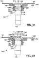
- FIG. 2A shows the drain connector of FIG. 1 in a closed state, with the plunger illustrated in elevation view, and with the drain flange and circumferential sealing O-rings illustrated in cross-sectional view.
- FIG. 2B illustrates the same views as FIG. 2A , but with the drain connector in an open state - i.e., with the plunger 110 elevated relative to the drain flange 150 to open a fluid pathway through the passages 126A-126C into the hollow core 125.
- FIG. 3A is a bottom view of the drain flange 150 shown in FIGS. 1 and 2A -2B, illustrating the flange lip 151, lower surface 153, flange body 155, lower body surface 158, aperture 165, inner surface 166, and retaining lip 170 all as described previously.
- FIG. 3B is a top view of the drain flange 150 shown in FIGS. 1 , 2A-2B , and 3A, illustrating the flange lip 151, the upper surface 152, the aperture 165, the inner surface 166, and the upper surface portion 168, all as described previously.
- FIG. 4A is an elevation view of the plunger of FIG. 1 and FIGS. 2A -2B, illustrating the first closed end 111, the second open end 112, the exterior surface 121, the body 115, the tapered neck portion 118, the flared portion 141, the outer tapered surface 142, the O-ring recesses 131, 132, and the passages 126A-126C, all as described previously.
- FIG. 4B is a bottom view of the plunger of FIG. 4A , illustrating the exterior surface 121, the interior surface 122, the hollow core 125, the tapered neck portion 118, and the outer tapered surface 142, all as described previously.
- FIG. 4C is a top view of the plunger of FIGS. 4A-4B , illustrating the first closed end 111.
- compatibility e.g., non-reactivity
- Each of the plunger 110 and the flange 150 preferably comprises a single piece, but may alternatively be constructed from multiple pieces if desired.
- One or more sensors of various types may be incorporated into the flange and/or plunger to monitor at least one characteristic of a substance contained or flowing within the drain connector. Temperature, pH, conductivity, and pressure are examples of desirable characteristics of substances to be sensed or monitored with appropriate sensors.
- plungers having perimeters that are substantially circular in shape, and likewise drain flange apertures that are substantially circular in shape
- such structures are intended to be illustrative only and plungers and drain flanges disclosed herein are not limited to particular shapes. Plungers and flanges having circular or oval shapes are preferred, but other shapes may be used.
- passages 126A-126C are shown as being defined through the wall 120, a plunger 110 may only require a single passage. If desired, a multiplicity of passages 126A-126C may be defined through the wall 120 of any size suitable for an intended application. In one embodiment, the passages 126A-126C may be sized to provide straining or filtration utility. In another embodiment, the passages may be sized to permit air or other gases to be introduced from the plunger 110 into a suitable receptacle, such as to supply oxygen to biological moieties contained therein or to furnish gaseous reactants for a desired reaction. In this vein, the adjective “drain” as applied to the term “drain connector” herein is intended to refer to the ability of such a device to modulate flow, but without being limited to modulating flow in only one direction.
- FIGS. 2A-2B Two states of operation of the drain connector 100 are shown in FIGS. 2A-2B , with FIG. 2A showing the drain connector 100 in a closed state and FIG. 2B showing the drain connector 100 in an open state.
- the upper surface 111 of the first closed end is preferably substantially flush with the upper surface 152 of the drain flange 150. This minimizes any interference between the drain connector 100 and a mixing element or other agitation means disposed within a processing receptacle to which the drain connector 100 may be attached.
- the outer tapered surface 142 of the plunger 110 is mated against the corresponding inner tapered surface 169 of the flange, and both the first (upper) O-ring 133 and second (lower) O-ring 134 are sealingly engaged against the inner surface 166 of the drain flange 150.
- Such sealing engagement prevents the passage of any solids, liquids, or gases through the drain connector 100.
- Upward movement of the plunger 110 eliminates sealing engagement between the first (upper) O-ring 133 and the inner surface 166, thus exposing the passages 126A-126C and placing the drain connector 100 in an open state.
- substances located within a processing receptacle to which the drain connector 100 is attached may flow through the passages 126A-126C into the hollow core 125 and exit the receptacle (not shown).
- FIGS. 5A-5C An alternative hollow plunger 210 useful with embodiments according to the invention is shown in FIGS. 5A-5C .
- the plunger 210 has a body 215, a first closed end 211, a second open end 212, and a wall 220 with an exterior surface 221 and an interior surface 222 defining a hollow core 225 leading or open to the open end 212.
- Multiple passages 226A-226D are defined through the wall 220 and extend into the hollow core 225.
- this plunger 210 includes protruding sealing rings 235, 236, with one ring 235 disposed above the passages 226A-226D and the other ring 236 disposed below the passages 226A-226D.
- the plunger 210 further includes a second travel stop 245 that limits the outward or upward movement of the plunger 210 relative to an associated drain flange.
- the upper surface 246 of the second travel stop 245 is intended to contact the lower body surface 158 of the drain flange 150 shown in the preceding figures.
- the travel stop 245 may be integrally formed to the plunger 210, or, as shown in FIG. 5C , it may be formed as a separate element having an interior cavity 248 for mating with the exterior surface 221 of the plunger 210.
- FIGS 6A-6B The joining of a plunger 110 with an outlet tube 50 is shown in FIGS 6A-6B .
- An outlet tube having an outer wall 51 and an inner wall 52 defining a bore 53 may be fitted to the plunger 110 by inserting the tapered neck 118 into the tube 50.
- Various types of outlet tubes may be used, with silicone tubing being one preferred type. Sealing between the outlet tube 50 and the plunger 110 may be further assured with adhesive, or more preferably, with an external clamp or strap (not shown).
- the outlet tube 50 functions to conduct substances from (or alternatively, to) the hollow core 125 of the plunger 110. If desired, the outlet tube 50 may also be used to actuate the drain connector 100.
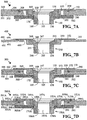
- FIG. 7A illustrates a portion of a first fluid receptacle 300 including a processing tank 301 (with only a lower portion of the tank 301 being illustrated).
- the tank 301 has an inner surface 302, an outer surface 303, and defines an aperture 305 for receiving a drain flange 150.
- a hollow plunger 110 or 210 as disclosed herein would be provided in conjunction with the drain flange 150 to form a drain connector 100).
- the tank 301 further defines a shallow recess 306 for accepting the flange lip 152, and a narrower but deeper recess 308 for holding an O-ring 309 to promote sealing between the flange 150 and the tank 301.
- Compressive contact between the flange 150 and the tank 301 is maintained by way of a retaining element 380 engaging the retaining lip 170 protruding from the flange body 155.
- the lower surface 382 of the retaining element 380 engages the retaining lip 170
- the upper surface 383 of the retaining element 380 engages the lower surface 303 of the tank 301, thus exerting a downward force on the flange 150 that compresses the flange lip 152 against the O-ring 309.
- Removal of the retaining element 382 permits the flange 150 to be separated from the tank 301 if desired.
- the use of such a retaining element 382 permits the drain connector 100 to be used with and easily installed in a wide variety of different types of processing tanks.
- a drain connector may be joined to a processing bag fabricated of substantially non-rigid materials to form a processing receptacle.
- FIG. 7B illustrates a receptacle 400 having a drain connector including a drain flange 250 permanently joined to a non-rigid processing bag 491.
- the drain flange 250 is substantially similar to the drain flange 150 disclosed previously herein, but with the omission of any retaining lip.
- the drain flange 250 includes a flange lip 251 having an upper surface 252 and a lower surface 253, and a flange body 255 defining an aperture 265 bounded by an inner surface 266 and tapered surface portions 267-269.
- a lower body surface 258 provides the lower boundary of the flange 250 and surrounds the aperture 265.
- the flange 250 may be joined to the bag 491 along by any appropriate means, such as ultrasonic welding, solvent welding, thermal bonding, and adhesive bonding.
- the interface between the inner surface 492 of the bag 491 and the lower surface 253 of the flange lip 251 forms a joint 499.
- One advantage of joining the drain connector / drain flange 250 to the processing bag 491 to form a processing receptacle is that the receptacle can be sterilized as a combined assembly, and then packaged together following sterilization in a sealed package. This ensures sterile conditions are maintained during transport and minimizes the chance of contamination when the receptacle is readied for first use.
- the receptacle is particularly well-suited for disposable operation.
- the bag may be structurally supported within a rigid tank or a substantially open frame with appropriate hooks or other fasteners (not shown).
- FIG. 7C A processing receptacle according to another embodiment including a processing tank, a processing bag, and a drain connector is illustrated in FIG. 7C .
- the receptacle 500 includes a processing bag 591 having a drain flange 150 joined thereto, with the bag 591 being supported by a tank 501 that also provides secondary containment utility in case the bag 591 should rupture.
- the bag 591 is permanently joined to the drain flange 150, such as by ultrasonic welding.
- the bag 591 is compressed between the drain flange 150 and the tank 501 without being permanently joined thereto, so as to permit the drain flange 150 to be re-used with different disposable bag 591.
- An aperture 505, 595 is defined in each of the tank 501 and bag 591 to receive the flange 150.
- the bag 591 has an outer surface 593 and an inner surface 592 joined to the lower surface 153 of the flange lip 151 to form a joint 599.
- the lower surface 593 of the bag 591 is disposed against the inner surface 502 of the tank 501, with the tank 501 further defining a recess 508 containing an O-ring 509 to promote sealing between the tank 501 and the bag 591. Compression of the bag 591 against the tank 501 is maintained by the retaining element 580, which engages the retaining lip 170 protruding from the flange body 155.
- Such compression may be used in conjunction with the O-ring 509 to maintain sealing engagement between the drain flange 150 and the bag 591.
- the lower surface 582 of the retaining element 580 engages the retaining lip 170
- the upper surface 583 of the retaining element 580 engages the lower surface 503 of the tank 501
- a downward force on the flange 150 that compresses the flange lip 152 and the lower surface 593 of the bag 591 against the O-ring 509.
- a disposable processing bag 591 with the associated drain connector / drain flange 150 may be used with a rigid mixing tank 501 such that the mixing tank need not be re-used or re-sterilized between batches.
- FIG. 7D A processing receptacle according to another embodiment including a processing tank, a processing bag, and a drain connector is illustrated in FIG. 7D .
- the receptacle 500A closely resembles the receptacle 500 illustrated in FIG. 7C , with the addition of a second O-ring 519A between the drain flange 150A and the bag 591A, with a slightly thicker drain flange 150A to accommodate such O-ring 519A, and with a slightly thinner bag 591A.
- the bag 591A is not permanently joined to the drain flange 150A.
- the bag 591A is supported by a tank 501A providing secondary containment utility.
- An aperture 505A, 595A is defined in each of the tank 501A and the bag 591A to receive the drain flange 151A.
- the bag 591A has an outer surface 593A and an inner surface 592A joined to the lower surface 153A of the flange lip 151A to form a joint 599A.
- the lower surface 153A of the drain flange 150A further defines a recess 518A for receiving an O-ring 519A adapted to provide a seal between the drain flange 591A and the bag 591A.
- the lower surface 593A of the bag 591A is disposed against the inner surface 502A of the tank 501A, with the tank 501A further defining a recess 508A containing another O-ring 509 to promote sealing between the tank 501A and the bag 591A.
- Compression of the bag 591A against the tank 501A is maintained by the retaining element 580, which engages the retaining lip 170A protruding from the flange body 155A.
- Such compression may be used in conjunction with both O-rings 509A, 519A to maintain sealing engagement between the tank 501A and the bag 591A, and between the bag 591A and the drain flange 150A.
- a disposable processing bag 591A with the associated drain connector / drain flange 150 may be used with a rigid mixing tank 501 such that the mixing tank need not be re-used or re-sterilized between batches.
- the drain flange 591A may be re-sterilized and re-used with another mixing bag / mixing tank assembly if desired.
- a selectively closeable drain connector includes a moveable hollow plunger with a plunger body having a first closed end, a second open end, and a wall with an exterior surface and with an interior surface bounding a hollow core.
- the plunger body defines at least one passage extending from the exterior surface into the hollow core.
- the drain flange defines an aperture bounded by an inner surface and adapted to receive the plunger, with the inner surface having a first and a second raised sealing element.
- a tank or bag (referred to hereinafter as a tank 601 with the understanding that the tank 601 may refer to either a tank or bag) for use with a drain connector as described herein is illustrated in FIG. 8 .
- the tank 601 includes a cavity-defining sealed sleeve 620 joined to (e.g., the top 604 of) the tank 601 and protruding into the tank 601.
- the cavity 623 contains a mixing paddle 625 and support rod 624.
- the function of the sleeve 620 is to serve as an isolation barrier between the mixing elements 624, 625 and the interior of the tank 601.
- the sleeve 620 may be fabricated from a polymer film with a lower seam 621 provided after the mixing elements 624, 625 are inserted into the sleeve 620, such that any of the mixing elements 624, 625 may be permanently retained by the sleeve 620.
- the sleeve 620 may include a reinforced aperture-defining coupling guide 628 to permit the support rod 625 to be inserted into the sleeve 620 and/or permit an external mixing mechanism (not shown) to be coupled to the support rod 625 while resisting puncture or damage of the sleeve 620.
- the paddle 625 and rod 624 contained within the sleeve 625 are preferably directed in a circular, oval, or other appropriate path within the tank 601 to stir or mix substances contained therein.
- An upper seam 622 preferably joins the sleeve 620 to the upper wall 604 of the tank 601, with the sleeve 620 preferably permanently joined to the tank 601.
- Both the tank 601 and sleeve 620 preferably comprise polymeric materials suitable for economical single use (i.e., disposable) operation.
- each of the tank 601 and sleeve 620 comprises a polymeric film; in a particularly preferred embodiment, each of the tank 601 and sleeve 620 comprises a substantially optically transmissive or transparent film.
- a substantially open external frame may be provided to support the tank 601 with associated hooks or connectors (not shown).
- the upper wall of the tank further defines apertures 631, 632 serving as access ports for the admission of substances into the tank 601.
- Each aperture or port 631, 632 preferably has an associated supply line 633, 634, sealing element 635, 636, and coupling element 637, 638.
- the lower wall 606 of the tank 601 defines an aperture 605 adapted to receive a drain connector flange (such as any of the flanges 150, 250 described herein), which may be joined to the tank 601 by any appropriate means.
- the combination of the tank 601 and flange 150, 250 may be called a processing receptacle 600, similar to the receptacles 300, 400, 500, 500A shown in FIGS. 7A-7D .
- FIG. 9 Another tank or bag (referred to hereinafter as a tank 701 with the understanding that the tank 701 may refer to either a tank or bag) to which three drain connectors 100A, 100B, 100C (preferably identical or substantially similar to the drain connector 100 as provided herein) are coupled is illustrated in FIG. 9 .
- the tank 701 has an upper surface 704, a lower surface 706, an outer wall 703 and an inner wall 702.
- the tank 701 further includes a cavity defining sealed sleeve 720 joined to the top 704 of the tank 701 and protruding into the tank 701.
- the sleeve contains a mixing paddle 725 and support rod 724.
- the function of the sleeve 720 is to serve as an isolation barrier between the mixing elements 724, 725 and the interior of the tank 701.
- the paddle 725 and rod 724 contained within the sleeve 725 are preferably directed in a circular, oval, or other appropriate path within the tank 601 to stir or mix substances contained therein.
- a coupling guide 728 is preferably provided to permit the support rod 724 to be inserted into the sleeve 720 without damaging the sleeve 720.
- One or more external mixing mechanisms or elements (not shown) is preferably provided and coupled from above to cause the mixing rod 724 and paddle 725 to move within the tank 701.
- the tank 701 defines three apertures or ports 705A-705C each having an associated drain connector 100A-100C.
- Each drain connector 100A-100C has a flange 150A-150C and plunger (with the sealed end 111A-111C of each plunger labeled in FIG. 9 ), an associated inlet/outlet tube 50A-50C, and a coupling 149A-149C associated with the inlet/outlet tube 50A-50C.
- the combination of the tank 701, sleeve 720 and contents 724, 725, and drain connectors 100A-100C may be termed a processing receptacle 700.
- substances are supplied to the tank 701 through, e.g., the upper drain connectors 100B, 100C, which may be opened for as long or short a period as desired and/or intermittently operated if desired. Substances are then processed within the tank 701. Following any processing steps, a drain connector, e.g., the lower drain connector 100A, may be opened to permit processed substances to exit the tank 701.
- FIGS. 10A-10B Another drain connector 800 useful with embodiments according to the present invention is shown in FIGS. 10A-10B .
- this drain connector 800 is actuated by withdrawing the plunger 810 into the flange 850 in the direction away from the associated tank or bag (not shown).
- FIG. 10A shows the connector 800 in a closed state
- FIG. 10B shows the connector 800 in an open state.
- the hollow plunger 810 has a body 815, a first closed end 811, a second open end 812, and a wall 820 with an exterior surface 821 and an interior surface 822 defining a hollow core 825 leading to or open to the open end 812.
- Multiple passages 826A-826C are defined through the wall 820 and extend from the exterior surface 821 into the hollow core 825.
- the exterior surface 821 of the wall 820 further defines a circumferential recess 831 adjacent to the passages 826A-826C, with the recess 831 preferably being sized and shaped to retain an O-ring or equivalent sealing element.
- sealing elements which would fit into the recess 831 defined in the plunger 810, and into the recess 881 defined in the flange 850, have been omitted from FIGS. 10A-10B , but it is to be understood that sealing elements are preferably provided.
- the plunger body 815 preferably includes a tapered neck portion 818 intended to mate with an outlet tube.
- the flange 850 includes a flange lip 851 having an upper surface 852, a lower surface 853, and a peripheral edge 854.
- the flange lip 851 extends outward from the flange body 855.
- the flange body 855 defines an aperture 865 having a first portion bounded by an inner sealing surface 866 and a second, enlarged portion bounded by an inner recess surface 866A.
- the first portion bounded by the inner sealing surface 866 preferably has substantially constant interior dimensions to permit the plunger 810 to slide freely therein, with the O-ring (not shown) retained in the circumferential recess 831 contacting the inner surface 866.
- the flange body 855 includes an outer surface 864 with a retaining lip 870 protruding therefrom.
- the flange body 855 further includes a lower body surface 858 that is preferably annular in shape surrounding the aperture 865.
- the drain connector 800 When the drain connector 800 is in the closed state (shown in FIG. 10A ), sealing engagement between the sealing elements (not shown) fitted into the circumferential recess 831 and the inner sealing surface 866 prevents the passage of any substances from the tank (not shown) into the hollow core 825.
- the drain connector 800 When the drain connector 800 is in the open state (as shown in FIG. 10B ), substances (e.g., contents of a tank) are permitted to flow into the recess 865 and through the passages 826A-826C into the hollow core 825 to exit the drain connector 800.
- drain 800 connector includes two circumferential seals between the plunger 810 and the flange 850, with the passages 826A-826C leading to the hollow core 825 being disposed between the seals.
- Processing receptacles including drain connectors coupled to processing tanks and/or bags all as described herein may be put to various desirable uses.
- such a processing receptacle may be used to mix and/or react industrial chemicals.
- a first method step at least one material is to a processing receptacle as described herein.
- the at least one material is processed within the receptacle.
- the at least one processed material is drained from the receptacle through a drain connector as described herein.
- one or more materials may be supplied to the receptacle through the drain connector prior to the draining step.
- Such a step may include the supply of a gas such as oxygen or air to assist in aerating or facilitating a chemical reaction of materials disposed within the receptacle.
- a processing receptacle as described herein may be used to assist in pharmaceutical development, formulation, or manufacture.
- at least one material selected from: drug precursor materials, therapeutic agents, binding materials, bulk materials, coloring agents, flavoring agents, stabilizing agents, preservatives, and reagents is added to a processing receptacle.
- the at least one material is processed (e.g., mixed and/or reacted) within the receptacle.
- the at least one processed material is drained from the receptacle through a drain connector as described herein.
- one or more materials e.g., including gases
- a processing receptacle as described herein may be used to process biological materials.
- a first method step at least one of various biological materials is added to a processing receptacle. Non-biological materials may also be added if desired for a particular application.
- the at least one biological material is processed (e.g., mixed, reacted, and/or fermented) within the receptacle.
- the at least one processed material is drained from the receptacle through a drain connector as described herein.
- one or more materials e.g., including gases
- a processing receptacle as described herein may be used to process semiconductor precursor and/or processing materials.
- wet solutions may be combined with abrasive materials to yield chemical mechanical polishing or planarization (CMP) slurries.
- CMP chemical mechanical polishing or planarization
- a first method step at least one semiconductor precursor and/or processing material is added to a processing receptacle.
- the at least one semiconductor precursor and/or processing material is processed within the receptacle.
- the at least one processed material is drained from the receptacle through a drain connector as described herein.
- one or more materials e.g., including gases
Landscapes
- Engineering & Computer Science (AREA)
- Chemical & Material Sciences (AREA)
- Chemical Kinetics & Catalysis (AREA)
- Mechanical Engineering (AREA)
- General Engineering & Computer Science (AREA)
- External Artificial Organs (AREA)
- Closures For Containers (AREA)
- Details Of Rigid Or Semi-Rigid Containers (AREA)
- Bag Frames (AREA)
- Quick-Acting Or Multi-Walled Pipe Joints (AREA)
- Separation Using Semi-Permeable Membranes (AREA)
- Medical Preparation Storing Or Oral Administration Devices (AREA)
- Containers And Packaging Bodies Having A Special Means To Remove Contents (AREA)
Claims (30)
- Substanzverarbeitungsbehälter (300, 400, 500, 500A, 600, 700) mit einem selektiv schließbaren Drain-Anschluss (100, 800) und einem Materialverarbeitungsbeutel (491, 591, 591A, 601, 701) umfassend eine Beutelinnenfläche (492, 592, 592A) und eine Beutelaußenfläche (493), wobei der Drain-Anschluss (100, 800) umfasst:einen Kolben (110, 210, 810) mit einem Kolbenkörper (115, 215, 815) mit einem ersten geschlossenen Ende (111, 211, 811), einem zweiten offenen Ende (112, 212, 812), einer Wand (120, 220, 820) mit einer Außenfläche (121, 221, 821) und mit einer Innenfläche (122, 222, 822) abgrenzend einen hohlen Kern (125, 225, 825) und einem ersten und zweiten Umfangsdichtelement (133, 134, 235, 236), angeordnet entlang der Außenfläche (121, 221, 821), der Kolbenkörper (115, 215, 815) weiterhin zumindest einen Durchgang (126A-126C, 226A-226D, 826A-826C) definierend, der sich von der Außenfläche (121, 221, 821) in den hohlen Kern (125, 225, 825) erstreckt und zwischen dem ersten und dem zweiten Umfangsdichtelement (133, 134, 235, 236) angeordnet ist; undeinen Drain-Flansch (150, 150A, 250, 850), der eine Öffnung (165, 265, 865) definiert, um den Kolben (110, 210, 810) aufzunehmen, die Öffnung (165, 265, 865) wird durch eine Innenfläche (166, 266, 866) abgegrenzt, ausgestaltet, um in die ersten und zweiten Umfangsdichtelemente (133, 134, 235, 236) abdichtend einzugreifen, wenn sich der Drain-Anschluss (100, 800) in einem geschlossenen Zustand befindet, und abdichtend in das zweite Umfangsdichtungselement (134, 236) einzugreifen, wenn sich der Drain-Anschluss (100, 800) in einem offenen Zustand befindet;wobei einer der Kolben (110, 210, 810) und der Drain-Flansch (150, 150A, 250, 850) ausgestaltet sind, sich relativ zu dem anderen zu bewegen; undwobei der Drain-Flansch (150, 150A, 250, 850) eine sie radial erstreckenden Flanschlippe (151, 151A, 251, 851) aufweist, wobei eine untere Fläche (153, 153A, 253, 853) der Flanschlippe (151, 151A 251, 851) die Beutelinnenfläche (492, 522, 592A) einer Bodenwand (606, 706) des Beutels (491, 591, 591 A, 601, 701) berührt und abdichtend eingreift, und das erste geschlossene Ende (111, 211, 811) des Kolbens (110, 210, 810) fluchtend mit einer oberen Fläche (152, 152A, 252, 852) der sich radial erstreckenden Flanschlippe (151, 151A, 251, 851) angeordnet ist, wenn sich der Drain-Anschluss (100, 800) in einem geschlossenen Zustand befindet.
- Substanzverarbeitungsbehälter (300, 400, 500, 500A, 600, 700) nach Anspruch 1, bei welchem der Drain-Flansch (150, 150A, 250, 850) mit der Beutelinnenfläche (492, 592, 592A) der Bodenwand (606, 706) des Beutels (491, 591, 591A, 601, 701) durch ein Verfahren ausgewählt aus Ultraschallschweißen, Lösungsmittelschweißen, thermischem Verbinden und Kleben, verbunden ist/wird.
- Substanzverarbeitungsbehälter (300, 400, 500, 500A, 600, 700) nach Anspruch 1, bei welchem ein Abschnitt des Kolbens (110, 210) angeordnet ist, um sich ein Innenvolumen des Beutels (491, 591, 591A, 601, 701) zu bewegen, wenn sich der Drain-Anschluss (100, 800) in einem offenen Zustand befindet.
- Substanzverarbeitungsbehälter (300, 400, 500, 500A, 600, 700) nach Anspruch 3, bei welchem das erste Umfangsdichtelement (133) entlang dem oberen Abschnitt des Kolbens (110, 210) angeordnet ist und angeordnet ist, um sich in ein Innenvolumen des Beutels (491, 591, 591 A, 601, 701) zu bewegen, wenn sich der Drain-Anschluss (100) in einem offenen Zustand befindet.
- Substanzverarbeitungsbehälter (300, 400, 500, 500A, 600, 700) nach Anspruch 1, bei welchem ein Umfang von mindestens einem Abschnitt des Kolbenkörpers (115, 215, 815) im Wesentlichen kreisförmig ist.
- Substanzverarbeitungsbehälter (300, 400, 500, 500A, 600, 700) nach Anspruch 1, bei welchem der Kolben (100, 210) ferner mindestens einen Bewegungsanschlag (141, 241, 245) umfasst.
- Substanzverarbeitungsbehälter (300, 400, 500, 500A, 600, 700) nach Anspruch 6, bei welchem der zumindest eine Bewegungsanschlag (141, 241, 245) einen nach außen ausgeweiteten Abschnitt (141, 241) umfasst, der entlang des ersten geschlossenen Endes (111, 211) des Kolbens (110, 210) angeordnet ist.
- Substanzverarbeitungsbehälter (300, 400, 500, 500A, 600, 700) nach Anspruch 6, bei welchem der zumindest eine Bewegungsanschlag (141, 241, 245) einen erhöhten Abschnitt oder erhöhten Ring (245) umfasst, der entlang der Außenfläche (121, 221) des Kolbenkörpers (115, 215) angeordnet ist.
- Substanzverarbeitungsbehälter (300, 400, 500, 500A, 600, 700) nach Anspruch 1, bei welchem jedes von dem ersten und zweiten Umfangsdichtelement (133, 134, 235, 236) eine zugehörige Umfangsaussparung (131, 132) aufweist, die in der Außenfläche (121, 221, 821) der Kolbenkörperwand (120, 220, 820) definiert ist, und jedes von dem ersten und dem zweiten Umfangsdichtelement (133.134, 235, 236) einen O-Ring (133, 134) umfasst, der so angepasst ist, dass dieser in die zugehörige Umfangsaussparung (131, 132) passt.
- Substanzverarbeitungsbehälter (300, 400, 500, 500A, 600, 700) nach Anspruch 1, bei welchem jedes von dem ersten und zweiten Umfangsdichtelement (133, 134, 235, 236) einen erhöhten Dichtungsring (235 236), der einstückig mit dem Kolben (110, 210, 810) oder daran angepasst ist, ausgebildet ist.
- Substanzverarbeitungsbehälter (300, 400, 500, 500A, 600, 700) nach Anspruch 1, ferner umfassend ein hohles Auslassrohr (50), welches mit dem Kolben (110, 210, 810) entlang des zweiten offenen Endes (112, 212, 812) in Eingriff steht.
- Substanzverarbeitungsbehälter (300, 400, 500, 500A, 600, 700) nach Anspruch 11, bei welchem der Drain-Anschluss (100, 800) aus einem offenen Zustand in einen geschlossenen Zustand oder umgekehrt durch die Bewegung des Auslassrohr (50) betätigt ist/wird
- Substanzverarbeitungsbehälter (300, 400, 500, 500A, 600, 700) nach Anspruch 1, bei welchem der zumindest eine Durchgang (126A-126C, 226A-226D, 826A-826C) eine Vielzahl von Durchgängen (126A-126C, 226A-226D, 826A-826C) umfasst.
- Substanzverarbeitungsbehälter (300, 400, 500, 500A, 600, 700) nach Anspruch 1, bei welchem die Innenfläche (166, 266) des Drain-Flansches (150, 150A, 250) im wesentlichen konstante Innenabmessungen zwischen den erste und zweiten Umfangsdichtelementen (133, 134, 235, 236) aufweist, wenn sich der Drain-Anschluss (100) in einem geschlossenen Zustand befindet.
- Substanzverarbeitungsbehälter (300, 400, 500, 500A, 600, 700) nach Anspruch 1, bei welchem der Drain-Flansch (150, 150A, 250, 850) ein im Wesentlichen optisch durchlässiges Material umfasst.
- Substanzverarbeitungsbehälter (300, 400, 500, 500A, 600, 700) nach Anspruch 1, bei welchem der Beutel (491, 591, 591A, 601, 701) eine Außenwand (703) umfasst, die ein Polymerfolienmaterial umfasst.
- Substanzverarbeitungsbehälter (300, 400, 500, 500A, 600, 700) nach Anspruch 16, bei welchem das Polymerfolienmaterial im Wesentlichen optisch durchlässig ist.
- Substanzverarbeitungsbehälter (300, 400, 500, 500A, 600, 700) nach Anspruch 16, ferner umfassend einen Sensor, der an einem von dem Kolben (110, 210, 810), dem Drain-Flansch (150, 150A, 250, 850) und dem Auslassrohr (50), das mit einem der Kolben (110, 210, 810) und dem Drain-Flansch (150, 150A, 250, 850) verbunden ist, befestigt ist, wobei der Sensor ausgestaltet ist, um zumindest eine Substanzeigenschaft, die im Drain-Anschluss (80, 100) enthalten ist oder darin strömt, zu überwachen.
- Substanzverarbeitungsbehälter (300, 400, 500, 500A, 600, 700) nach Anspruch 1, bei welchem der Dichtungseinsatz zwischen der unteren Fläche (153, 153A, 253, 853) der Flanschlippe (151, 151A, 251 851) und die Bodenwand (606, 706) des Materialverarbeitungsbeutels (491, 591, 591A, 601, 701) nicht-permanent ist und angepasst ist, um zu ermöglichen, dass der Drain-Anschluss (100, 800) aus dem Materialverarbeitungsbeutel (491, 591, 591A, 601, 701) entfernt werden kann.
- Substanzverarbeitungsbehälter (300, 400, 500, 500A, 600, 700) nach Anspruch 1, bei welchem zumindest ein O-Ring (519A) zwischen dem Drain-Flansch (150, 150A, 250, 850) und dem Materialverarbeitungsbeutel (491, 591, 591A, 601, 701) angeordnet ist.
- Substanzverarbeitungsbehälter (300, 400, 500, 500A, 600, 700) nach einem der Ansprüche 1 bis 18, bei welchem eine obere Begrenzung (152, 152A, 252, 852) des Drain-Flansches (150, 150A, 250, 850) im Wesentlichen bündig mit der Bodenwand (606, 706) des Materialverarbeitungsbeutels (491, 591, 591A, 601, 701) ist.
- Substanzverarbeitungsbehälter (300, 400, 500, 500A, 600, 700) nach einem der Ansprüche 1 bis 21, ferner umfassend einen hohlen Behälter (501, 501A), worin der Materialverarbeitungsbeutel (501, 501A, 591A, 601, 701) angeordnet ist/wird.
- Substanzverarbeitungsbehälter (300, 400, 500, 500A, 600, 700) nach einem der Ansprüche 1 bis 22, ferner umfassend ein bewegliches Mischelement (624, 625, 724, 725), welches im Innenvolumen des Materialverarbeitungsbeutels (491, 591, 591A, 601, 701) angeordnet ist.
- Substanzverarbeitungsbehälter (300, 400, 500, 500A, 600, 700) nach einem der Ansprüche 1 bis 22, bei welchem der Materialbearbeitungsbeutel (491, 591, 591A, 601, 701) eine einen Hohlraum definierende abgedichtete Hülse (620, 720) umfasst, die sich in ein Innenvolumen des Materialbearbeitungsbeutels (491, 591, 591 A, 601, 701) erstreckt und ausgestaltet ist, um zumindest ein bewegliches Mischelement (624, 625, 724, 725) zu enthalten.
- Substanzverarbeitungsbehälter (300, 400, 500, 500A, 600, 700) nach einem der Ansprüche 1 bis 24, bei welchem Materialverarbeitungsbeutel (491, 591, 591A, 601, 701) und der Drain-Anschluss (100, 800) sterilisiert sind.
- Verfahren zur Herstellung eines sterilen Verarbeitungsbehälters (300, 400, 500, 500A, 600, 700), wobei das Verfahren die Schritte umfasst:Verbinden eines selektiv schließbaren Drain-Anschlusses (100, 800) an ein Materialverarbeitungsbeutel (491, 591, 591A, 601, 701) mit einer Beutelinnenfläche (492, 592, 592A) und eine Beutelaußenfläche (493), wobei der Drain-Anschluss (100, 800) umfasst:einen Hohlkolben (110, 210,810) mit einem einteiligen Kolbenkörper (115,215, 815) mit einem ersten geschlossenen Ende (111 211 811), einem zweiten offenen Ende (112, 212, 812), einer Wand (120, 220, 820) mit einer Außenfläche (121, 221, 821) und mit einer Innenfläche (122, 222, 822), einen hohlen Kern (125, 225, 825) abgrenzend, und einem ersten und zweiten Umfangsdichtelement (133, 134, 235, 236), entlang der Außenfläche (121, 221, 821) angeordnet, und einem Bewegungsanschlag (141, 241, 245), wobei der Kolbenkörper (115, 215, 815) ferner nach oben zumindest einen Durchgang (126A-126C, 226A-226D, 826A-826C) definiert, der sich von der Außenfläche (121, 221, 821) in den hohlen Kern (125, 225, 825) erstreckt und zwischen dem ersten und dem zweiten Umfangsdichtungselement (133, 134, 235, 236) angeordnet ist; undein Drain-Flansch (150, 150A, 250, 850), der eine zur Aufnahme des Kolbens (110, 210, 810) ausgestaltete Öffnung (165, 265, 865) definiert, wobei die Öffnung (165, 265, 865) durch eine Innenfläche (166, 266, 866) abgegrenzt ist, ausgestaltet um abdichtend in das ersten und das zweite Umfangsdichtelement (133, 134, 235, 236) einzugreifen, wenn der Drain-Anschluss (100, 800) in einem geschlossenen Zustand ist, und um abdichtend in das zweite Umfangsdichtelement (134, 236) einzugreifen, wenn der Drain-Anschluss (100, 800) in einem offenen Zustand ist;wobei jeder von dem Kolben (110, 210, 810) und dem Drain-Anschluss (150, 150A, 250, 850) ausgestaltet ist, um sich relativ zu dem anderen zu bewegen; und wobei der Drain-Flansch (150, 150A, 250, 850) eine sich radial erstreckenden Flanschlippe (151, 151A, 251, 851) aufweist, wobei eine untere Fläche (153, 153A, 253, 853) der Flanschlippe (151, 151A 251, 851) die Beutelinnenfläche (492, 522, 592A) einer Bodenwand (606, 706) des Beutels (491, 591, 591A, 601, 701) berührt und abdichtend eingreift, und das erste geschlossene Ende (111, 211, 811) des Kolbens (110, 210, 810) fluchtend mit einer oberen Fläche (152, 152A, 252, 852) der sich radial erstreckenden Flanschlippe (151, 151A, 251, 851) angeordnet ist, wenn sich der Drain-Anschluss (100, 800) in einem geschlossenen Zustand befindet; undSterilisieren des Fluidverarbeitungsbehälters (300, 400, 500, 500A, 600, 700).
- Verfahren nach Anspruch 26, bei welchem das Verbinden des Drain-Anschlusses (100, 800) an der Beutel (491, 591, 591A, 601, 701) ein Verbinden der Flanschlippe (151, 151A, 251, 851) an die Beutelinnenfläche (492, 592, 592A) der Bodenwand (606, 706) des Beutels (491, 591, 591 A, 601, 701) durch ein Verfahren ausgewählt aus Ultraschallschweißen, Lösungsmittelschweißen, thermischem Verbinden und Kleben, umfasst.
- Verfahren nach Anspruch 26, ferner umfassend den Schritt des Verpackens des Behälters (300, 400, 500, 500A, 600, 700) zur Sterilfluidverarbeitung in einer versiegelten Verpackung.
- Verfahren nach Anspruch 26, bei welchem das Verbinden des Drain-Anschlusses (100, 800) an den Beutel (591, 591a, 601, 701) ein abdichtendes Eingreifen mit dem Drain-Flansch (150, 150A, 250, 850) an einer Bodenwand (606, 706) des Beutels (491, 591, 591a, 601, 701) mit einer oberen Begrenzung (152, 152A, 252, 852) des Drains-Flansch (150, 150A, 250, 850) im Wesentlichen bündig mit die Bodenwand (606, 706) des Beutels (491, 591, 591A, 601, 701) umfasst.
- Verfahren nach Anspruch 26, bei welchem der Beutel (591, 591 A, 601, 701) eine einen Hohlraum definierende abgedichtete Hülse (620, 720) umfasst, die sich in ein Innenvolumen des Beutels (491, 591, 591 A, 601, 701) erstreckt und ausgestaltet ist, um zumindest ein bewegliches Mischelement (624, 625, 724, 725) zu enthalten, und wobei die abgedichtete Hülse (620, 720) zusammen mit dem Fluidverarbeitungsbehälter (300, 400, 500, 500A, 600, 700) sterilisiert wird.
Applications Claiming Priority (2)
| Application Number | Priority Date | Filing Date | Title |
|---|---|---|---|
| US71846605P | 2005-09-19 | 2005-09-19 | |
| PCT/US2006/036214 WO2007035592A2 (en) | 2005-09-19 | 2006-09-18 | Drain connector for substance processing receptacle |
Publications (3)
| Publication Number | Publication Date |
|---|---|
| EP1934406A2 EP1934406A2 (de) | 2008-06-25 |
| EP1934406A4 EP1934406A4 (de) | 2010-08-04 |
| EP1934406B1 true EP1934406B1 (de) | 2018-02-07 |
Family
ID=37889400
Family Applications (1)
| Application Number | Title | Priority Date | Filing Date |
|---|---|---|---|
| EP06803747.2A Active EP1934406B1 (de) | 2005-09-19 | 2006-09-18 | Ablaufverbinder für einen behälter zur verarbeitung von substanzen |
Country Status (8)
| Country | Link |
|---|---|
| US (1) | US7614607B2 (de) |
| EP (1) | EP1934406B1 (de) |
| JP (1) | JP5055283B2 (de) |
| CN (1) | CN101627242B (de) |
| CA (1) | CA2623078A1 (de) |
| IL (1) | IL190195A (de) |
| TW (1) | TWI414371B (de) |
| WO (1) | WO2007035592A2 (de) |
Families Citing this family (24)
| Publication number | Priority date | Publication date | Assignee | Title |
|---|---|---|---|---|
| US20110052102A1 (en) * | 2005-09-19 | 2011-03-03 | Sven Stiers | Drain connector for substance processing receptacle |
| EP2279039A2 (de) * | 2008-04-17 | 2011-02-02 | Sartorius Stedim Biotech GmbH | Flexibler beutel mit einer mischvorrichtung |
| GB0821151D0 (en) * | 2008-11-19 | 2008-12-24 | Airbus Uk Ltd | Valve apparatus |
| DE102008060773A1 (de) | 2008-12-05 | 2010-06-10 | Sartorius Stedim Biotech Gmbh | Verschluss für einen Behälter |
| JP2013533171A (ja) * | 2010-04-19 | 2013-08-22 | エイティーエムアイ ビーブイビーエイ | 流体処理および貯蔵容器用のドレンコネクタ |
| DE102010019691A1 (de) | 2010-05-07 | 2011-11-10 | Sartorius Stedim Biotech Gmbh | Ventil für einen Behälter |
| ES2670645T3 (es) | 2011-03-07 | 2018-05-31 | Nordson Corporation | Racor sanitario con entrada parabólica |
| FR2978225B1 (fr) * | 2011-07-19 | 2014-05-16 | Sartorius Stedim Biotech Sa | Valve a fonctionnement selectif pour un recipient a usage biopharmaceutique. |
| USD714437S1 (en) | 2012-01-13 | 2014-09-30 | Nordson Corporation | Bag port |
| USD729908S1 (en) * | 2012-03-21 | 2015-05-19 | Blucher Metal A/S | Emergency drain |
| CN104379210A (zh) * | 2012-06-12 | 2015-02-25 | 弗洛森斯有限公司 | 新型管阀及其使用 |
| WO2014007206A1 (ja) * | 2012-07-02 | 2014-01-09 | 株式会社テイエルブイ | フロート式ドレントラップ |
| JP5989432B2 (ja) * | 2012-07-18 | 2016-09-07 | 日東電工株式会社 | 塗膜保護シート |
| US9321558B2 (en) * | 2012-09-19 | 2016-04-26 | Perimeter Brand Packaging, Llc | Insert assembly for beverage container |
| USD758554S1 (en) * | 2012-09-20 | 2016-06-07 | Blucher Metal A/S | Emergency drain |
| US20140183222A1 (en) * | 2012-10-19 | 2014-07-03 | Rust-Oleum Corporation | Propellantless Aerosol System |
| PT2951452T (pt) * | 2013-02-01 | 2016-11-04 | Asociación Centro De Investigación Coop En Biomateriales | Sistema de agitação não intrusivo |
| US9841111B2 (en) * | 2014-01-09 | 2017-12-12 | Kyb Corporation | Solenoid valve |
| US10234042B2 (en) | 2017-06-01 | 2019-03-19 | Pall Corporation | Drain valve with rotatable angled outlet |
| US20200189786A1 (en) * | 2018-12-12 | 2020-06-18 | Goodrich Corporation | Composite potable water tank and method of forming |
| US11703132B2 (en) * | 2019-06-21 | 2023-07-18 | Emd Millipore Corporation | Zero dead leg valve |
| EP4355487A1 (de) * | 2021-06-18 | 2024-04-24 | Becton Dickinson France | Flexibler rumpf und starre trägeranordnung zur übertragung von sterilen komponenten aus einem behälter |
| US12031654B2 (en) | 2021-12-28 | 2024-07-09 | Cytiva Us Llc | Fluid connector |
| US12044342B2 (en) | 2021-12-28 | 2024-07-23 | Cytiva Us Llc | Fluid connector with slidable member |
Family Cites Families (19)
| Publication number | Priority date | Publication date | Assignee | Title |
|---|---|---|---|---|
| US2692112A (en) * | 1954-10-19 | szitar | ||
| US2842382A (en) * | 1955-02-07 | 1958-07-08 | Imp Brass Mfg Co | Valved connector |
| US3219278A (en) * | 1964-02-05 | 1965-11-23 | Santarelli Vincent | Shut-off nozzle |
| US3768469A (en) * | 1971-12-20 | 1973-10-30 | Bendix Corp | Indicator for volume ventilator apparatus |
| US4362255A (en) * | 1980-10-24 | 1982-12-07 | Liqui-Box Corporation | Barrier spout and cap for flexible bags or pouches |
| US4413806A (en) | 1981-07-29 | 1983-11-08 | Glenys Anderson | Shut-off valve assembly |
| US4779736A (en) * | 1985-09-27 | 1988-10-25 | Gordon Geasland | Tubular plastic shipping, storage and dispensing container |
| US4801124A (en) | 1988-01-25 | 1989-01-31 | Shippers Paper Products Company | Disposable valve |
| US5579953A (en) * | 1994-08-30 | 1996-12-03 | Plastic Systems Inc. | Liquid container and valve |
| JPH08219381A (ja) * | 1995-02-17 | 1996-08-30 | Orion Mach Co Ltd | 電磁式ドレントラップ |
| JP3132805B2 (ja) * | 1995-12-28 | 2001-02-05 | 神鋼パンテツク株式会社 | 容器用の排出弁 |
| NL1009812C2 (nl) * | 1998-08-05 | 2000-02-08 | Euro Maintenance Lease Prod Bv | Afsluitklep voor een container. |
| EP0997154A1 (de) | 1998-11-01 | 2000-05-03 | Newform N.V. | Sterilisierbarer Behälter mit sterilisierbarem Adapter zum Ankoppeln an den Eingang einer Trennkammer |
| DE19903479C2 (de) * | 1999-01-29 | 2003-03-20 | Schott Glas | Verfahren zum Befestigen von Kunststoffteilen an Kannen |
| US6705591B2 (en) * | 2001-10-02 | 2004-03-16 | Colder Products Company | Poppet valve and method of making same |
| JP4179991B2 (ja) | 2002-04-26 | 2008-11-12 | ミリポア・コーポレイション | 使い捨て無菌流体輸送デバイス |
| EP1522355B9 (de) * | 2002-07-25 | 2012-02-29 | Kunimichi Sato | Ressourcenrecyclingverfahren, -system und -behälter |
| US7083323B2 (en) | 2003-05-19 | 2006-08-01 | Advanced Technology Materials, Inc. | Flexible mixing bag for mixing solids, liquids and gases |
| US7249880B2 (en) | 2003-10-14 | 2007-07-31 | Advanced Technology Materials, Inc. | Flexible mixing bag for mixing solids, liquids and gases |
-
2006
- 2006-09-18 EP EP06803747.2A patent/EP1934406B1/de active Active
- 2006-09-18 CN CN2006800395279A patent/CN101627242B/zh not_active Expired - Fee Related
- 2006-09-18 JP JP2008531397A patent/JP5055283B2/ja not_active Expired - Fee Related
- 2006-09-18 WO PCT/US2006/036214 patent/WO2007035592A2/en not_active Ceased
- 2006-09-18 US US11/522,679 patent/US7614607B2/en active Active
- 2006-09-18 CA CA002623078A patent/CA2623078A1/en not_active Abandoned
- 2006-09-19 TW TW095134518A patent/TWI414371B/zh active
-
2008
- 2008-03-16 IL IL190195A patent/IL190195A/en not_active IP Right Cessation
Non-Patent Citations (1)
| Title |
|---|
| None * |
Also Published As
| Publication number | Publication date |
|---|---|
| IL190195A0 (en) | 2008-11-03 |
| CA2623078A1 (en) | 2007-03-29 |
| TWI414371B (zh) | 2013-11-11 |
| US7614607B2 (en) | 2009-11-10 |
| US20070102450A1 (en) | 2007-05-10 |
| EP1934406A2 (de) | 2008-06-25 |
| JP5055283B2 (ja) | 2012-10-24 |
| CN101627242B (zh) | 2013-01-30 |
| IL190195A (en) | 2011-05-31 |
| TW200722196A (en) | 2007-06-16 |
| WO2007035592A2 (en) | 2007-03-29 |
| WO2007035592A3 (en) | 2009-09-03 |
| JP2009511363A (ja) | 2009-03-19 |
| EP1934406A4 (de) | 2010-08-04 |
| CN101627242A (zh) | 2010-01-13 |
Similar Documents
| Publication | Publication Date | Title |
|---|---|---|
| EP1934406B1 (de) | Ablaufverbinder für einen behälter zur verarbeitung von substanzen | |
| US20120260608A1 (en) | Drain connector for substance processing receptacle | |
| US20130167960A1 (en) | Drain connector for fluid processing and storage containers | |
| AU2018203721B9 (en) | Drain valve with rotatable angled outlet | |
| CN101163538A (zh) | 混合系统及相关混合器 | |
| US9341293B2 (en) | Connection having communication between biopharmaceutical containers and/or conduits | |
| AU2017382934B9 (en) | Container coupling and opening device with probe | |
| US12540302B2 (en) | System and method for draining a flexible bioprocessing bag | |
| CN114829570A (zh) | 一种器具 | |
| US20140001392A1 (en) | Fluid Transfer Device | |
| US20070087598A1 (en) | Interconnect and method for joining receptacles | |
| EP4463646A1 (de) | Steriler fluidischer verbinder mit wiederverbindbaren verbindern und verfahren zur aseptischen verbindung |
Legal Events
| Date | Code | Title | Description |
|---|---|---|---|
| PUAI | Public reference made under article 153(3) epc to a published international application that has entered the european phase |
Free format text: ORIGINAL CODE: 0009012 |
|
| 17P | Request for examination filed |
Effective date: 20080331 |
|
| AK | Designated contracting states |
Kind code of ref document: A2 Designated state(s): AT BE BG CH CY CZ DE DK EE ES FI FR GB GR HU IE IS IT LI LT LU LV MC NL PL PT RO SE SI SK TR |
|
| AX | Request for extension of the european patent |
Extension state: AL BA HR MK RS |
|
| R17D | Deferred search report published (corrected) |
Effective date: 20090903 |
|
| RIC1 | Information provided on ipc code assigned before grant |
Ipc: F16K 31/00 20060101AFI20090909BHEP |
|
| A4 | Supplementary search report drawn up and despatched |
Effective date: 20100705 |
|
| DAX | Request for extension of the european patent (deleted) | ||
| 17Q | First examination report despatched |
Effective date: 20111028 |
|
| RAP1 | Party data changed (applicant data changed or rights of an application transferred) |
Owner name: PALL TECHNOLOGY UK LIMITED |
|
| GRAP | Despatch of communication of intention to grant a patent |
Free format text: ORIGINAL CODE: EPIDOSNIGR1 |
|
| INTG | Intention to grant announced |
Effective date: 20170825 |
|
| GRAS | Grant fee paid |
Free format text: ORIGINAL CODE: EPIDOSNIGR3 |
|
| GRAA | (expected) grant |
Free format text: ORIGINAL CODE: 0009210 |
|
| AK | Designated contracting states |
Kind code of ref document: B1 Designated state(s): AT BE BG CH CY CZ DE DK EE ES FI FR GB GR HU IE IS IT LI LT LU LV MC NL PL PT RO SE SI SK TR |
|
| REG | Reference to a national code |
Ref country code: GB Ref legal event code: FG4D |
|
| REG | Reference to a national code |
Ref country code: AT Ref legal event code: REF Ref document number: 968947 Country of ref document: AT Kind code of ref document: T Effective date: 20180215 Ref country code: CH Ref legal event code: EP |
|
| REG | Reference to a national code |
Ref country code: IE Ref legal event code: FG4D |
|
| REG | Reference to a national code |
Ref country code: DE Ref legal event code: R096 Ref document number: 602006054669 Country of ref document: DE |
|
| REG | Reference to a national code |
Ref country code: NL Ref legal event code: FP |
|
| REG | Reference to a national code |
Ref country code: AT Ref legal event code: MK05 Ref document number: 968947 Country of ref document: AT Kind code of ref document: T Effective date: 20180207 |
|
| PG25 | Lapsed in a contracting state [announced via postgrant information from national office to epo] |
Ref country code: ES Free format text: LAPSE BECAUSE OF FAILURE TO SUBMIT A TRANSLATION OF THE DESCRIPTION OR TO PAY THE FEE WITHIN THE PRESCRIBED TIME-LIMIT Effective date: 20180207 Ref country code: LT Free format text: LAPSE BECAUSE OF FAILURE TO SUBMIT A TRANSLATION OF THE DESCRIPTION OR TO PAY THE FEE WITHIN THE PRESCRIBED TIME-LIMIT Effective date: 20180207 Ref country code: CY Free format text: LAPSE BECAUSE OF FAILURE TO SUBMIT A TRANSLATION OF THE DESCRIPTION OR TO PAY THE FEE WITHIN THE PRESCRIBED TIME-LIMIT Effective date: 20180207 Ref country code: FI Free format text: LAPSE BECAUSE OF FAILURE TO SUBMIT A TRANSLATION OF THE DESCRIPTION OR TO PAY THE FEE WITHIN THE PRESCRIBED TIME-LIMIT Effective date: 20180207 |
|
| PG25 | Lapsed in a contracting state [announced via postgrant information from national office to epo] |
Ref country code: IS Free format text: LAPSE BECAUSE OF FAILURE TO SUBMIT A TRANSLATION OF THE DESCRIPTION OR TO PAY THE FEE WITHIN THE PRESCRIBED TIME-LIMIT Effective date: 20180607 Ref country code: PL Free format text: LAPSE BECAUSE OF FAILURE TO SUBMIT A TRANSLATION OF THE DESCRIPTION OR TO PAY THE FEE WITHIN THE PRESCRIBED TIME-LIMIT Effective date: 20180207 Ref country code: AT Free format text: LAPSE BECAUSE OF FAILURE TO SUBMIT A TRANSLATION OF THE DESCRIPTION OR TO PAY THE FEE WITHIN THE PRESCRIBED TIME-LIMIT Effective date: 20180207 Ref country code: GR Free format text: LAPSE BECAUSE OF FAILURE TO SUBMIT A TRANSLATION OF THE DESCRIPTION OR TO PAY THE FEE WITHIN THE PRESCRIBED TIME-LIMIT Effective date: 20180508 Ref country code: BG Free format text: LAPSE BECAUSE OF FAILURE TO SUBMIT A TRANSLATION OF THE DESCRIPTION OR TO PAY THE FEE WITHIN THE PRESCRIBED TIME-LIMIT Effective date: 20180507 Ref country code: LV Free format text: LAPSE BECAUSE OF FAILURE TO SUBMIT A TRANSLATION OF THE DESCRIPTION OR TO PAY THE FEE WITHIN THE PRESCRIBED TIME-LIMIT Effective date: 20180207 Ref country code: SE Free format text: LAPSE BECAUSE OF FAILURE TO SUBMIT A TRANSLATION OF THE DESCRIPTION OR TO PAY THE FEE WITHIN THE PRESCRIBED TIME-LIMIT Effective date: 20180207 |
|
| REG | Reference to a national code |
Ref country code: FR Ref legal event code: PLFP Year of fee payment: 13 |
|
| PG25 | Lapsed in a contracting state [announced via postgrant information from national office to epo] |
Ref country code: IT Free format text: LAPSE BECAUSE OF FAILURE TO SUBMIT A TRANSLATION OF THE DESCRIPTION OR TO PAY THE FEE WITHIN THE PRESCRIBED TIME-LIMIT Effective date: 20180207 Ref country code: RO Free format text: LAPSE BECAUSE OF FAILURE TO SUBMIT A TRANSLATION OF THE DESCRIPTION OR TO PAY THE FEE WITHIN THE PRESCRIBED TIME-LIMIT Effective date: 20180207 Ref country code: EE Free format text: LAPSE BECAUSE OF FAILURE TO SUBMIT A TRANSLATION OF THE DESCRIPTION OR TO PAY THE FEE WITHIN THE PRESCRIBED TIME-LIMIT Effective date: 20180207 |
|
| REG | Reference to a national code |
Ref country code: DE Ref legal event code: R097 Ref document number: 602006054669 Country of ref document: DE |
|
| PG25 | Lapsed in a contracting state [announced via postgrant information from national office to epo] |
Ref country code: DK Free format text: LAPSE BECAUSE OF FAILURE TO SUBMIT A TRANSLATION OF THE DESCRIPTION OR TO PAY THE FEE WITHIN THE PRESCRIBED TIME-LIMIT Effective date: 20180207 Ref country code: CZ Free format text: LAPSE BECAUSE OF FAILURE TO SUBMIT A TRANSLATION OF THE DESCRIPTION OR TO PAY THE FEE WITHIN THE PRESCRIBED TIME-LIMIT Effective date: 20180207 Ref country code: SK Free format text: LAPSE BECAUSE OF FAILURE TO SUBMIT A TRANSLATION OF THE DESCRIPTION OR TO PAY THE FEE WITHIN THE PRESCRIBED TIME-LIMIT Effective date: 20180207 |
|
| PLBE | No opposition filed within time limit |
Free format text: ORIGINAL CODE: 0009261 |
|
| STAA | Information on the status of an ep patent application or granted ep patent |
Free format text: STATUS: NO OPPOSITION FILED WITHIN TIME LIMIT |
|
| 26N | No opposition filed |
Effective date: 20181108 |
|
| PG25 | Lapsed in a contracting state [announced via postgrant information from national office to epo] |
Ref country code: SI Free format text: LAPSE BECAUSE OF FAILURE TO SUBMIT A TRANSLATION OF THE DESCRIPTION OR TO PAY THE FEE WITHIN THE PRESCRIBED TIME-LIMIT Effective date: 20180207 |
|
| PG25 | Lapsed in a contracting state [announced via postgrant information from national office to epo] |
Ref country code: MC Free format text: LAPSE BECAUSE OF FAILURE TO SUBMIT A TRANSLATION OF THE DESCRIPTION OR TO PAY THE FEE WITHIN THE PRESCRIBED TIME-LIMIT Effective date: 20180207 |
|
| REG | Reference to a national code |
Ref country code: CH Ref legal event code: PL |
|
| REG | Reference to a national code |
Ref country code: IE Ref legal event code: MM4A |
|
| PG25 | Lapsed in a contracting state [announced via postgrant information from national office to epo] |
Ref country code: LU Free format text: LAPSE BECAUSE OF NON-PAYMENT OF DUE FEES Effective date: 20180918 |
|
| PG25 | Lapsed in a contracting state [announced via postgrant information from national office to epo] |
Ref country code: IE Free format text: LAPSE BECAUSE OF NON-PAYMENT OF DUE FEES Effective date: 20180918 |
|
| PG25 | Lapsed in a contracting state [announced via postgrant information from national office to epo] |
Ref country code: LI Free format text: LAPSE BECAUSE OF NON-PAYMENT OF DUE FEES Effective date: 20180930 Ref country code: CH Free format text: LAPSE BECAUSE OF NON-PAYMENT OF DUE FEES Effective date: 20180930 |
|
| PG25 | Lapsed in a contracting state [announced via postgrant information from national office to epo] |
Ref country code: TR Free format text: LAPSE BECAUSE OF FAILURE TO SUBMIT A TRANSLATION OF THE DESCRIPTION OR TO PAY THE FEE WITHIN THE PRESCRIBED TIME-LIMIT Effective date: 20180207 |
|
| PG25 | Lapsed in a contracting state [announced via postgrant information from national office to epo] |
Ref country code: PT Free format text: LAPSE BECAUSE OF FAILURE TO SUBMIT A TRANSLATION OF THE DESCRIPTION OR TO PAY THE FEE WITHIN THE PRESCRIBED TIME-LIMIT Effective date: 20180207 Ref country code: HU Free format text: LAPSE BECAUSE OF FAILURE TO SUBMIT A TRANSLATION OF THE DESCRIPTION OR TO PAY THE FEE WITHIN THE PRESCRIBED TIME-LIMIT; INVALID AB INITIO Effective date: 20060918 |
|
| PGFP | Annual fee paid to national office [announced via postgrant information from national office to epo] |
Ref country code: DE Payment date: 20250926 Year of fee payment: 20 |
|
| PGFP | Annual fee paid to national office [announced via postgrant information from national office to epo] |
Ref country code: NL Payment date: 20250925 Year of fee payment: 20 |
|
| PGFP | Annual fee paid to national office [announced via postgrant information from national office to epo] |
Ref country code: BE Payment date: 20250925 Year of fee payment: 20 Ref country code: GB Payment date: 20250923 Year of fee payment: 20 |
|
| PGFP | Annual fee paid to national office [announced via postgrant information from national office to epo] |
Ref country code: FR Payment date: 20250925 Year of fee payment: 20 |