EP1935514A1 - Appareil et procédé pour nettoyer des objects, en particulier de disques minces - Google Patents
Appareil et procédé pour nettoyer des objects, en particulier de disques minces Download PDFInfo
- Publication number
- EP1935514A1 EP1935514A1 EP06026053A EP06026053A EP1935514A1 EP 1935514 A1 EP1935514 A1 EP 1935514A1 EP 06026053 A EP06026053 A EP 06026053A EP 06026053 A EP06026053 A EP 06026053A EP 1935514 A1 EP1935514 A1 EP 1935514A1
- Authority
- EP
- European Patent Office
- Prior art keywords
- shower
- basin
- fluid
- wafers
- carrier
- Prior art date
- Legal status (The legal status is an assumption and is not a legal conclusion. Google has not performed a legal analysis and makes no representation as to the accuracy of the status listed.)
- Granted
Links
Images



Classifications
-
- H—ELECTRICITY
- H10—SEMICONDUCTOR DEVICES; ELECTRIC SOLID-STATE DEVICES NOT OTHERWISE PROVIDED FOR
- H10P—GENERIC PROCESSES OR APPARATUS FOR THE MANUFACTURE OR TREATMENT OF DEVICES COVERED BY CLASS H10
- H10P72/00—Handling or holding of wafers, substrates or devices during manufacture or treatment thereof
- H10P72/04—Apparatus for manufacture or treatment
- H10P72/0402—Apparatus for fluid treatment
- H10P72/0406—Apparatus for fluid treatment for cleaning followed by drying, rinsing, stripping, blasting or the like
- H10P72/0411—Apparatus for fluid treatment for cleaning followed by drying, rinsing, stripping, blasting or the like for wet cleaning or washing
- H10P72/0414—Apparatus for fluid treatment for cleaning followed by drying, rinsing, stripping, blasting or the like for wet cleaning or washing using mainly spraying means, e.g. nozzles
-
- B—PERFORMING OPERATIONS; TRANSPORTING
- B08—CLEANING
- B08B—CLEANING IN GENERAL; PREVENTION OF FOULING IN GENERAL
- B08B3/00—Cleaning by methods involving the use or presence of liquid or steam
- B08B3/02—Cleaning by the force of jets or sprays
- B08B3/024—Cleaning by means of spray elements moving over the surface to be cleaned
-
- H—ELECTRICITY
- H10—SEMICONDUCTOR DEVICES; ELECTRIC SOLID-STATE DEVICES NOT OTHERWISE PROVIDED FOR
- H10P—GENERIC PROCESSES OR APPARATUS FOR THE MANUFACTURE OR TREATMENT OF DEVICES COVERED BY CLASS H10
- H10P72/00—Handling or holding of wafers, substrates or devices during manufacture or treatment thereof
- H10P72/10—Handling or holding of wafers, substrates or devices during manufacture or treatment thereof using carriers specially adapted therefor, e.g. front opening unified pods [FOUP]
- H10P72/13—Horizontal boat type carrier whereby the substrates are vertically supported, e.g. comprising rod-shaped elements
-
- H—ELECTRICITY
- H10—SEMICONDUCTOR DEVICES; ELECTRIC SOLID-STATE DEVICES NOT OTHERWISE PROVIDED FOR
- H10P—GENERIC PROCESSES OR APPARATUS FOR THE MANUFACTURE OR TREATMENT OF DEVICES COVERED BY CLASS H10
- H10P72/00—Handling or holding of wafers, substrates or devices during manufacture or treatment thereof
- H10P72/10—Handling or holding of wafers, substrates or devices during manufacture or treatment thereof using carriers specially adapted therefor, e.g. front opening unified pods [FOUP]
- H10P72/15—Horizontal carrier comprising wall type elements whereby the substrates are vertically supported, e.g. comprising sidewalls
Definitions
- the invention relates generally to an apparatus and method for cleaning thin slices, such as semiconductor wafers, glass substrates, photomasks, compact discs, or the like.
- the invention relates to an apparatus and method for pre-cleaning semiconductor wafers after they have been made by sawing from a block.
- thin slices are understood according to the invention to mean objects which have a very small thickness in the range between 80 and 300 ⁇ m, such as 150 to 170 ⁇ m.
- the shape of the slices is arbitrary and may, for example, be essentially round (semiconductor wafer) or substantially rectangular or square (solar wafer), wherein the corners may be designed as angular, rounded or chamfered. These items are very fragile due to their small thickness.
- the invention relates to the pre-cleaning of such objects.
- the invention is not limited to the pre-cleaning of wafers. Rather, the invention generally includes the cleaning of thin slices, which are held sequentially at a defined distance from one another in a carrier device.
- the starting material which is usually present as a rectangular silicon block and is referred to as a substrate block or ingot
- This support device typically consists of a metal support, on which in turn a glass plate is attached as a carrier material.
- the substrate block to be processed is glued to the glass plate.
- other materials may be provided for the formation of the support means.
- the substrate block of monocrystalline or polycrystalline silicon in a disk-like manner, so that the respective saw cut extends into the glass plate.
- the wafer thus produced adheres to the glass plate with a longitudinal side (edge), namely, that facing the support means, through the adhesive bond.
- This blend is also referred to as kerf and can be reduced using thinner wires with diameters of, for example, 80 microns.
- kerf This blend is also referred to as kerf and can be reduced using thinner wires with diameters of, for example, 80 microns.
- a large number of chemical reactions of the reactants involved also occur on the wafer surface. Slurries, reaction products and conglomerates of slurry constituents and silicon, which often adhere to the surface of the wafer due to their consistency, are located between the wafers after sawing.
- the pre-cleaning is intended to wash out the slurry that is present on the surfaces of the wafers in the interstices of two substrates each. This pre-cleaning is the subject of the present invention.
- prepurifications for removing the slurry are known. They are usually performed by hand, by a shower head, from which a fluid flow exiting, is manually passed over the comb-like structure. This ensures that the slurry located in the columns of the substrate block is flushed out, at least in part. However, a predominant proportion remains in the gap-like gap.
- the surfaces of the wafers are usually already dried. In addition, slurry continues to adhere there, which greatly influences the further processing process.
- the object of the present invention is therefore to provide a device and a method with which the slurry can be removed at least partially automatically from the interstices of adjacent thin slices.
- the core idea of the invention is to propose a device and a method with which the cleaning process structured in different method steps is automatically (automatically) passed through.
- the device according to the invention is the subject of claim 1, while the method according to the invention is defined by the features of claim 11. Preferred embodiments are the subject of respective subclaims.
- a device which consists essentially of a support means, a shower device, and a basin.
- the carrier device which consists at least of the carrier material on which the substrate block is applied, comprises the thin disks (such as wafers) produced by sawing the substrate block. These are sequential, i. lined up in succession, wherein in each case a gap is formed between the individual wafers.
- the shower device is designed such that it preferably generates a fluid flow predominantly into the intermediate spaces over the entire longitudinal extent of the wafers.
- the entire cleaning process is provided in a fluid-fillable basin.
- the basin is dimensioned such that the support means completely fits into it.
- the pool is not filled. Rather, it serves to collect and remove the fluid flowing through the wafers.
- the showering process takes place in a basin whose level is adjusted such that the lower part of the substrate block (10 to 50%, particularly preferably about 30% of the wafer area) is in the liquid.
- the starting position of the cleaning process is determined such that the carrier device is transferred into a "basket-like" auxiliary device of the device according to the invention.
- the configuration of this auxiliary device is basically not fixed, as long as it is ensured that the fluid can reach the intermediate spaces between the wafers substantially unhindered and the substrate block and optionally detached wafers are held securely.
- this device is provided in the form of two pairs of rods extending parallel to each other in the longitudinal direction, one pair serving as a support and another pair laterally supporting the wafers.
- the comb-like structure of the substrate block fixed on the carrier device is aligned in such a way that the intermediate spaces are open to both the side walls and the bottom of the basin and thus freely accessible.
- the carrier device is located above the substrates supported by it.
- the auxiliary device is advantageously suspended in a pivoting device. This makes it possible to move the auxiliary device comprising the wafers within the basin.
- a preferred embodiment of the device according to the invention provides that the auxiliary device can be pivoted within the pelvis by at least 180 degrees.
- the device is designed such that a pivoting of 90 degrees is possible from the described starting position in both directions.
- the first step of the purification process according to the invention set out below can advantageously be preceded by a glycol pre-storage of the substrates to be treated.
- the shower device advantageously comprises a shower element which extends over the open side of the basin, and advantageously in the direction of the longitudinal extension of the support means. Furthermore, means are provided which the shower element over the open side pivot the pelvis and transport a fluid to the shower element.
- the shower element itself has at least one opening which is directed in the direction of the wafers to be cleaned, in particular to the intermediate spaces. Through this opening, the fluid flows to the interstices of the substrate block.
- process parameters can be varied by suitable known means.
- the shower element has a slot-like outlet opening, which preferably extends over the entire length of the element.
- This particular embodiment allows the application of a large amount of fluid, which is largely homogeneous in terms of their pressure-quantity ratio. In this way, the pressure of the fluid at the outlet opening of the shower element can be adjusted to a value between 0.1 and 1.0 bar, preferably to a value between 0.2 and 0.5 bar.
- either the shower device is moved relative to the fixed support device or the support device relative to the fixed shower device for the cleaning process, namely for the removal of the slurry from the interstices, either.
- both the carrier device and the shower device are moved relative to each other.
- the carrier device is initially positioned such that the respective open sides face upwards to the opening of the basin, to a side wall of the basin and towards the bottom of the basin.
- the carrier device pivots by 180 degrees, so that the state is reached again that the each open side up to the opening of the basin, facing a side wall of the basin and toward the bottom of the basin.
- the side previously positioned towards the bottom of the basin now points towards the open side of the basin and thus to the shower element, while the previously upwardly directed side is now aligned in the direction of the bottom of the basin.
- Another advantage of a high volume flow is that the wafers vibrate at least slightly, so that the slurry adhering to the surface of a wafer can be more easily released.
- the shower element is pivotable both about its own axis and locally above the opening of the basin.
- At least one ultrasound device is provided, which is optionally arranged stationary or movable within the pelvis.
- the ultrasound sources may also be oriented obliquely or parallel to the wafers.
- This cleaning process advantageously follows immediately after the cleaning process with the shower element.
- a cold fluid is used to allow optimal transmission of the ultrasonic waves.
- the temperature is adjusted to a value between 15 and 25 ° C to prevent chemical reactions and to ensure a substantially mechanical treatment.
- the ultrasonic wave cleaning process may preferably be assisted by a stationary crossflow device to create a fluid flow within the basin.
- the cross-flow device is designed such that the fluid flow is directed into the respective interspaces of two adjacent wafers and floats away the particles liberated by the ultrasound.
- the basin is emptied and another cleaning process with the shower element begins.
- the process can be repeated as needed by alternately alternating the cycles "cleaning process with shower element” and “cleaning process with ultrasound”.
- a particular embodiment of the invention provides that the substrate block is first cleaned using the shower device with a warm, if desired, suitable chemical additives such as surfactant-containing fluid, wherein the temperature is preferably between 35 and 40 ° C. Subsequently, the ultrasonic cleaning takes place within a cold fluid. Both processes may be repeated. As the last process, a cleaning process using the shower device with a cold fluid is provided.
- the latter has the advantage that the showering with a cold fluid prevents the wafers from "drying out” and thus possibly adhering any remaining slurry to the wafers.
- the shower fluid is aqueous according to the invention and is preferably adjusted to a temperature between 15 and 40 ° C, with a temperature between 30 and 40 ° C is particularly preferred.
- it comprises suitable non-foaming, nonionic surfactants in an amount of 0 to 1% by volume, with an amount of 0.1 to 0.5% by volume, based on the total amount of fluid, being particularly preferred.
- the surfactant (s) has an (averaged) pH of about 13.0, whereby the pH of the shower fluid advantageously to a preferred value less than 12.0, more preferably to a value between 10.5 and 11 , 0 can be set.
- the showering fluid may include caustic or acid and, if desired, other chemicals.
- the method according to the invention in a preferred embodiment may comprise a further process step of adhesive detachment.
- the support means if necessary. Transferred with the auxiliary device in a treatment tank, which includes a suitable depending on the nature of the adhesive used liquid. For example, the use of an acetic acid-containing aqueous liquid whose temperature and pH are particularly preferably adjusted to values around 40 ° C. or 3.0 to 4.0 has proved particularly suitable. Subsequently, the wafers are rinsed, which preferably takes place in that they are transferred with the auxiliary device in a water-filled kitchen sink.
- Another significant advantage of the method is that it can be easily incorporated into a subsequent processing process of the wafer. It has turned out to be particularly advantageous that the process parameters according to the invention can be set accurately and reproducibly, which makes it possible to treat larger quantities at the same quality level.
- a substrate block 1 to be cleaned is shown.
- the substrate block 1 is applied to a carrier device 2, which consists of a glass plate 3 and a fastening element 4.
- the substrate block 1 is in the embodiment shown here with its one side. 5 glued flat on the glass plate 3.
- wafers 6 individual substrates are produced, which are also referred to as wafers 6.
- a gap 7 in which the so-called slurry (not shown in the drawings) is located, which is to be removed by the cleaning process according to the invention.
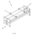
- the carrier device 2 with an auxiliary device 8, as shown in FIG Fig. 2 and 3 is shown, passed.
- the auxiliary device 8 comprises laterally arranged means 9, which with the device according to the Fig. 4 and 5 interact.
- a receiving device 10 which is flexibly positionable in its position for receiving the carrier device 2.
- the auxiliary device 8 is designed such that the substrate block 1 as shown in FIG Fig. 3 occupies a protected position against unwanted impact against an object.
- rods 11 are arranged as connecting elements between the provided means 9, which enclose the substrate block 1 between them.
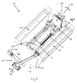
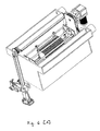
- the device 12 As shown in FIGS Fig. 4 and 5 to load with the auxiliary device 8.
- the device 12 itself shows a housing 13 which comprises a reservoir 14 which can be filled with a fluid.
- the basin 14 is dimensioned such that the auxiliary device 8 can be completely absorbed by the basin 14.
- Side of the basin 14 drainer 21 are provided.
- a pivoting device 15 is provided, which has the property of receiving the auxiliary device 8 at the corresponding means 9 and to pivot in and against the arrow 27 direction.
- the device 12 has a shower device 16.
- the shower device 16 consists essentially of a shower element 17, which extends in the direction L and parallel to the longitudinal extent of the support means 2.
- the shower element 17 is preferably guided at its two end faces via means and is pivoted in and against the direction of the arrow 18, so that the emerging from the shower element 17 fluid flow pours into the basin 12.
- the shower element 17 additionally pivots about its own axis 19 in and against the arrow direction 20.
- the exit opening facing downwardly in the basic position is designed slit-shaped.
- transverse flow means are provided within the basin 14 .
- These cross-flow devices have nozzle-like formations which generate a transverse flow within the basin 14 for the purpose of cleaning the substrate block 1.
- an ultrasonic device 23 with ultrasonic sources 24 is provided on the bottom side of the housing 13. This ultrasonic device 23 is switched on or off as needed and serves to additionally loosen or remove the slurry located in the interstices 7.
- ultrasonic device 23 may be provided that instead of the stationary fixed installation a mobile Ultrasonic device is provided, which is also movable within the basin 14 in any position.
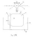
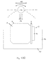
- the cleaning process begins by the shower device 16 is activated and the substrate block 1 at least approximately assumes the position as in Fig. 6B is shown.
- This position is characterized in that the fluid flow 26 emerging from the shower element 17 passes into the respective intermediate spaces 7, flows through them and can exit again in the direction of the bottom 25 of the basin 14.
- the slurry can be removed in this way from the respective interstices 7.
- the substrate block 1 pivots 180 degrees, so that he in Fig. 6C shown position occupies.
- the showering process begins in which the fluid stream 26 exits the shower member 17, in the respective interspaces 7 passes, flows through them and bottom side exits again. Depending on the degree of contamination, these process steps can be repeated as often as desired.
- the fluid stream 26 itself is tempered and can have temperatures between 25 degrees and 40 degrees Celsius.
- the present invention has been presented with regard to the treatment of silicon wafers.
- disc-shaped substrates of other materials such as plastic can be processed according to the invention.
Landscapes
- Cleaning Or Drying Semiconductors (AREA)
Priority Applications (2)
| Application Number | Priority Date | Filing Date | Title |
|---|---|---|---|
| DE502006004257T DE502006004257D1 (de) | 2006-12-18 | 2006-12-18 | Vorrichtung und Verfahren zum Reinigen von Gegenständen, insbesondere von dünnen Scheiben |
| EP06026053A EP1935514B1 (fr) | 2006-12-18 | 2006-12-18 | Appareil et procédé pour nettoyer des objects, en particulier de disques minces |
Applications Claiming Priority (1)
| Application Number | Priority Date | Filing Date | Title |
|---|---|---|---|
| EP06026053A EP1935514B1 (fr) | 2006-12-18 | 2006-12-18 | Appareil et procédé pour nettoyer des objects, en particulier de disques minces |
Publications (2)
| Publication Number | Publication Date |
|---|---|
| EP1935514A1 true EP1935514A1 (fr) | 2008-06-25 |
| EP1935514B1 EP1935514B1 (fr) | 2009-07-15 |
Family
ID=38066392
Family Applications (1)
| Application Number | Title | Priority Date | Filing Date |
|---|---|---|---|
| EP06026053A Not-in-force EP1935514B1 (fr) | 2006-12-18 | 2006-12-18 | Appareil et procédé pour nettoyer des objects, en particulier de disques minces |
Country Status (2)
| Country | Link |
|---|---|
| EP (1) | EP1935514B1 (fr) |
| DE (1) | DE502006004257D1 (fr) |
Cited By (6)
| Publication number | Priority date | Publication date | Assignee | Title |
|---|---|---|---|---|
| WO2009074297A3 (fr) * | 2007-12-10 | 2009-10-15 | Rena Sondermaschinen Gmbh | Dispositif et procédé de nettoyage d'objets |
| EP2458626A1 (fr) | 2010-11-29 | 2012-05-30 | RENA GmbH | Dispositif de nettoyage à retenue et procédé de nettoyage par section de tranches de silicium sciées |
| DE102011110592A1 (de) | 2011-08-18 | 2013-02-21 | Rena Gmbh | Verfahren zum Konditionieren von flachen Gegenständen |
| CN103894384A (zh) * | 2014-04-22 | 2014-07-02 | 深圳市中航大记工程制品有限公司 | 一种用于清洗设备的多维传动装置 |
| CN104475412A (zh) * | 2015-01-16 | 2015-04-01 | 哈尔滨立海机械制造有限公司 | 吸附式聚酯瓶脱标机 |
| CN104668239A (zh) * | 2015-02-10 | 2015-06-03 | 波达通信设备(广州)有限公司 | Pcba超声波清洗夹具、装置及方法 |
Citations (7)
| Publication number | Priority date | Publication date | Assignee | Title |
|---|---|---|---|---|
| US4358204A (en) * | 1980-09-22 | 1982-11-09 | Sidney Ellner | Ultrasonic cleaning apparatus |
| DE3815018A1 (de) * | 1987-05-06 | 1988-12-01 | Dan Science Co | Traegerreinigungs- und -trocknungsvorrichtung |
| WO2000029135A1 (fr) * | 1998-11-14 | 2000-05-25 | Miranda Henry R | Systeme de bain pour plaquettes en semi-conducteur a transducteurs soniques montes obliquement |
| US6139591A (en) | 1998-03-04 | 2000-10-31 | Tokyo Seimitsu Co., Ltd. | Wafer separating and cleaning apparatus and process |
| US20040025901A1 (en) * | 2001-07-16 | 2004-02-12 | Semitool, Inc. | Stationary wafer spin/spray processor |
| EP1457269A2 (fr) * | 2003-03-12 | 2004-09-15 | Ebara Corporation | Dispositif de nettoyage d'un substrat comportant des interconnexions métalliques |
| DE102004018817A1 (de) * | 2004-04-19 | 2005-11-03 | P.C.T. Systems, Inc., Fremont | Vorrichtung und Verfahren zum Bearbeiten von Substraten |
-
2006
- 2006-12-18 DE DE502006004257T patent/DE502006004257D1/de active Active
- 2006-12-18 EP EP06026053A patent/EP1935514B1/fr not_active Not-in-force
Patent Citations (7)
| Publication number | Priority date | Publication date | Assignee | Title |
|---|---|---|---|---|
| US4358204A (en) * | 1980-09-22 | 1982-11-09 | Sidney Ellner | Ultrasonic cleaning apparatus |
| DE3815018A1 (de) * | 1987-05-06 | 1988-12-01 | Dan Science Co | Traegerreinigungs- und -trocknungsvorrichtung |
| US6139591A (en) | 1998-03-04 | 2000-10-31 | Tokyo Seimitsu Co., Ltd. | Wafer separating and cleaning apparatus and process |
| WO2000029135A1 (fr) * | 1998-11-14 | 2000-05-25 | Miranda Henry R | Systeme de bain pour plaquettes en semi-conducteur a transducteurs soniques montes obliquement |
| US20040025901A1 (en) * | 2001-07-16 | 2004-02-12 | Semitool, Inc. | Stationary wafer spin/spray processor |
| EP1457269A2 (fr) * | 2003-03-12 | 2004-09-15 | Ebara Corporation | Dispositif de nettoyage d'un substrat comportant des interconnexions métalliques |
| DE102004018817A1 (de) * | 2004-04-19 | 2005-11-03 | P.C.T. Systems, Inc., Fremont | Vorrichtung und Verfahren zum Bearbeiten von Substraten |
Cited By (10)
| Publication number | Priority date | Publication date | Assignee | Title |
|---|---|---|---|---|
| WO2009074297A3 (fr) * | 2007-12-10 | 2009-10-15 | Rena Sondermaschinen Gmbh | Dispositif et procédé de nettoyage d'objets |
| EP2458626A1 (fr) | 2010-11-29 | 2012-05-30 | RENA GmbH | Dispositif de nettoyage à retenue et procédé de nettoyage par section de tranches de silicium sciées |
| DE102010052635A1 (de) | 2010-11-29 | 2012-05-31 | Rena Gmbh | Halte-Reinigungsvorrichtung und Verfahren zum abschnittsweisen Reinigen gesägter Wafer |
| DE102010052635B4 (de) * | 2010-11-29 | 2014-01-02 | Rena Gmbh | Halte-Reinigungsvorrichtung und Verfahren zum abschnittsweisen Reinigen gesägter Wafer |
| DE102011110592A1 (de) | 2011-08-18 | 2013-02-21 | Rena Gmbh | Verfahren zum Konditionieren von flachen Gegenständen |
| WO2013023799A1 (fr) | 2011-08-18 | 2013-02-21 | Rena Gmbh | Procédé de conditionnement d'objets plats |
| CN103894384A (zh) * | 2014-04-22 | 2014-07-02 | 深圳市中航大记工程制品有限公司 | 一种用于清洗设备的多维传动装置 |
| CN103894384B (zh) * | 2014-04-22 | 2015-12-23 | 深圳市中航大记工程制品有限公司 | 一种用于清洗设备的多维传动装置 |
| CN104475412A (zh) * | 2015-01-16 | 2015-04-01 | 哈尔滨立海机械制造有限公司 | 吸附式聚酯瓶脱标机 |
| CN104668239A (zh) * | 2015-02-10 | 2015-06-03 | 波达通信设备(广州)有限公司 | Pcba超声波清洗夹具、装置及方法 |
Also Published As
| Publication number | Publication date |
|---|---|
| EP1935514B1 (fr) | 2009-07-15 |
| DE502006004257D1 (de) | 2009-08-27 |
Similar Documents
| Publication | Publication Date | Title |
|---|---|---|
| EP2102896B1 (fr) | Dispositif et procédé pour nettoyer des objets, en particulier des plaquettes minces | |
| EP2218004B1 (fr) | Dispositif et procédé de nettoyage d'objets | |
| WO1997040524A1 (fr) | Dispositif pour traiter des substrats dans un recipient pour fluide | |
| DE102010052635B4 (de) | Halte-Reinigungsvorrichtung und Verfahren zum abschnittsweisen Reinigen gesägter Wafer | |
| EP2153960A2 (fr) | Support, procédé et dispositif de fabrication de tranches de silicium, ainsi que l'utilisation de la tranche de silicium fabriquée | |
| EP1935514B1 (fr) | Appareil et procédé pour nettoyer des objects, en particulier de disques minces | |
| WO2009074297A2 (fr) | Dispositif et procédé de nettoyage d'objets | |
| EP0412537A2 (fr) | Procédé et appareil pour la remise en état de toiles de polissage mécano-chimique, en particulier pour disques de semi-conducteur | |
| EP0497104A1 (fr) | Magasin pour contenir des pièces en forme de disques, en particulier des disques semi-conducteurs, dans un traitement de surface chimique en bains liquides | |
| EP1129823B1 (fr) | Procédé de régénération de plaquettes de semiconducteurs | |
| EP3061534A1 (fr) | Dispositif de nettoyage et procede de nettoyage de composants contamines par de la graisse, des proteines, des restes de dent, d'os ou de cartilage | |
| WO2011050945A1 (fr) | Scie à fil comprenant une zone de fil et des buses de nettoyage | |
| DE102007058260A1 (de) | Verfahren und Vorrichtung zur Reinigung eines gesägten Waferblocks | |
| DE19616402A1 (de) | Vorrichtung zum Behandeln von Substraten in einem Fluid-Behälter | |
| DE102008004548A1 (de) | Waferstapelreinigung | |
| EP1957247A1 (fr) | Dispositif et procédé de nettoyage d'un bloc scie de galettes semi-conductrices | |
| DE2543297C3 (de) | Verfahren zur Säuberung der Membranoberflächn einer Membrantrennvorrichtung | |
| WO2011086170A1 (fr) | Procédé et dispositif permettant d'obtenir des tranches ainsi qu'utilisation de ces derniers | |
| EP3188822B1 (fr) | Systeme de filtre autonettoyant à micro-tamis | |
| DE102005012244B4 (de) | Verfahren zur Reinigung von Gegenständen mittels Ultraschall | |
| DE202012103633U1 (de) | Vorrichtung zum nasschemischen Behandeln flacher Substrate | |
| DE102007059717B4 (de) | Vorrichtung und Verfahren zur Herstellung von Mikrobauteilen sowie Verwendung einer derartigen Vorrichtung | |
| DE102024122310A1 (de) | Verfahren zum Herauslösen von Objektteilen aus Objekten sowie Trägersystem | |
| WO2013023799A1 (fr) | Procédé de conditionnement d'objets plats | |
| DE10215044B4 (de) | Verfahren zum Ätzen und Trocknen von Substraten |
Legal Events
| Date | Code | Title | Description |
|---|---|---|---|
| PUAI | Public reference made under article 153(3) epc to a published international application that has entered the european phase |
Free format text: ORIGINAL CODE: 0009012 |
|
| 17P | Request for examination filed |
Effective date: 20080131 |
|
| AK | Designated contracting states |
Kind code of ref document: A1 Designated state(s): AT BE BG CH CY CZ DE DK EE ES FI FR GB GR HU IE IS IT LI LT LU LV MC NL PL PT RO SE SI SK TR |
|
| AX | Request for extension of the european patent |
Extension state: AL BA HR MK RS |
|
| GRAP | Despatch of communication of intention to grant a patent |
Free format text: ORIGINAL CODE: EPIDOSNIGR1 |
|
| AKX | Designation fees paid |
Designated state(s): DE FR GB |
|
| GRAS | Grant fee paid |
Free format text: ORIGINAL CODE: EPIDOSNIGR3 |
|
| GRAA | (expected) grant |
Free format text: ORIGINAL CODE: 0009210 |
|
| AK | Designated contracting states |
Kind code of ref document: B1 Designated state(s): DE FR GB |
|
| REG | Reference to a national code |
Ref country code: GB Ref legal event code: FG4D Free format text: NOT ENGLISH |
|
| REF | Corresponds to: |
Ref document number: 502006004257 Country of ref document: DE Date of ref document: 20090827 Kind code of ref document: P |
|
| PLBE | No opposition filed within time limit |
Free format text: ORIGINAL CODE: 0009261 |
|
| STAA | Information on the status of an ep patent application or granted ep patent |
Free format text: STATUS: NO OPPOSITION FILED WITHIN TIME LIMIT |
|
| 26N | No opposition filed |
Effective date: 20100416 |
|
| PGFP | Annual fee paid to national office [announced via postgrant information from national office to epo] |
Ref country code: FR Payment date: 20110107 Year of fee payment: 5 |
|
| PGFP | Annual fee paid to national office [announced via postgrant information from national office to epo] |
Ref country code: GB Payment date: 20101221 Year of fee payment: 5 |
|
| PGFP | Annual fee paid to national office [announced via postgrant information from national office to epo] |
Ref country code: DE Payment date: 20120222 Year of fee payment: 6 |
|
| GBPC | Gb: european patent ceased through non-payment of renewal fee |
Effective date: 20111218 |
|
| REG | Reference to a national code |
Ref country code: FR Ref legal event code: ST Effective date: 20120831 |
|
| PG25 | Lapsed in a contracting state [announced via postgrant information from national office to epo] |
Ref country code: GB Free format text: LAPSE BECAUSE OF NON-PAYMENT OF DUE FEES Effective date: 20111218 |
|
| PG25 | Lapsed in a contracting state [announced via postgrant information from national office to epo] |
Ref country code: FR Free format text: LAPSE BECAUSE OF NON-PAYMENT OF DUE FEES Effective date: 20120102 |
|
| PG25 | Lapsed in a contracting state [announced via postgrant information from national office to epo] |
Ref country code: DE Free format text: LAPSE BECAUSE OF NON-PAYMENT OF DUE FEES Effective date: 20130702 |
|
| REG | Reference to a national code |
Ref country code: DE Ref legal event code: R119 Ref document number: 502006004257 Country of ref document: DE Effective date: 20130702 |