EP1935706A2 - Elektrifizierte Sitzbefestigung - Google Patents
Elektrifizierte Sitzbefestigung Download PDFInfo
- Publication number
- EP1935706A2 EP1935706A2 EP07466028A EP07466028A EP1935706A2 EP 1935706 A2 EP1935706 A2 EP 1935706A2 EP 07466028 A EP07466028 A EP 07466028A EP 07466028 A EP07466028 A EP 07466028A EP 1935706 A2 EP1935706 A2 EP 1935706A2
- Authority
- EP
- European Patent Office
- Prior art keywords
- seat
- electrical contact
- fork
- electrified
- electrical
- Prior art date
- Legal status (The legal status is an assumption and is not a legal conclusion. Google has not performed a legal analysis and makes no representation as to the accuracy of the status listed.)
- Granted
Links
Images

Classifications
-
- B—PERFORMING OPERATIONS; TRANSPORTING
- B60—VEHICLES IN GENERAL
- B60N—SEATS SPECIALLY ADAPTED FOR VEHICLES; VEHICLE PASSENGER ACCOMMODATION NOT OTHERWISE PROVIDED FOR
- B60N2/00—Seats specially adapted for vehicles; Arrangement or mounting of seats in vehicles
- B60N2/005—Arrangement or mounting of seats in vehicles, e.g. dismountable auxiliary seats
- B60N2/015—Attaching seats directly to vehicle chassis
- B60N2/01508—Attaching seats directly to vehicle chassis using quick release attachments
- B60N2/01516—Attaching seats directly to vehicle chassis using quick release attachments with locking mechanisms
- B60N2/01583—Attaching seats directly to vehicle chassis using quick release attachments with locking mechanisms locking on transversal elements on the vehicle floor or rail, e.g. transversal rods
-
- B—PERFORMING OPERATIONS; TRANSPORTING
- B60—VEHICLES IN GENERAL
- B60N—SEATS SPECIALLY ADAPTED FOR VEHICLES; VEHICLE PASSENGER ACCOMMODATION NOT OTHERWISE PROVIDED FOR
- B60N2/00—Seats specially adapted for vehicles; Arrangement or mounting of seats in vehicles
- B60N2/02—Seats specially adapted for vehicles; Arrangement or mounting of seats in vehicles the seat or part thereof being movable, e.g. adjustable
- B60N2/0224—Non-manual adjustments, e.g. with electrical operation
-
- B—PERFORMING OPERATIONS; TRANSPORTING
- B60—VEHICLES IN GENERAL
- B60N—SEATS SPECIALLY ADAPTED FOR VEHICLES; VEHICLE PASSENGER ACCOMMODATION NOT OTHERWISE PROVIDED FOR
- B60N2/00—Seats specially adapted for vehicles; Arrangement or mounting of seats in vehicles
- B60N2/02—Seats specially adapted for vehicles; Arrangement or mounting of seats in vehicles the seat or part thereof being movable, e.g. adjustable
- B60N2/0224—Non-manual adjustments, e.g. with electrical operation
- B60N2/0244—Non-manual adjustments, e.g. with electrical operation with logic circuits
- B60N2/0264—Non-manual adjustments, e.g. with electrical operation with logic circuits characterised by the type of electrical connection, e.g. wiring, plugs or USB
Definitions
- the invention relates to the seat suspension, especially the removable vehicle seat, with a connection of the electrical installation of the seat to the electrical installation of the vehicle.
- the seats of modern vehicles are presently equipped with various electrical devices, e.g. a safety belt fastener sender, the electric ignition of the seatbelt pretensioner, a seat heater and the like fitted.
- various electrical devices e.g. a safety belt fastener sender, the electric ignition of the seatbelt pretensioner, a seat heater and the like fitted.
- the connection of these systems to the electrical system is easily feasible by means of cables with connector, but with removable seat, which are installed in multi-purpose vehicles, the electrically conductive connection by means of an automatic connection in a seat installation in the vehicle and a decoupling in the Disassembly can be ensured.
- the suspension forms a bolt for attachment to the vehicle floor, and a fork for attachment to the seat and rotatable, attachable to this bolt.
- the bolt is provided with at least one stop for defining the axial fork position, wherein at least one of these stops at least a first electrical contact is attached, which can be connected to the electrical installation of the vehicle.
- the fork is provided on the corresponding side of the matched stop with at least a second electrical contact that can be connected to the electrical installation of the seat. The second electrical contact is automatically inserted in the installation of the seat in the vehicle in the electrical connection with the first contact.
- the first electrical contact is located at least on the peripheral region of the stop, with the advantage especially on its underside, where it is well secured against damage or short circuit.
- the stop advantageously has a shape of a blunt camshaft, with a downwardly directed vertex.
- the pin including stopper is formed at least partially of electrically non-conductive material, e.g. through the casting of plastic on a metal support. The first electrical contact and its lead in this plastic are at least partially melted so that only the required for contact with the second electrical contact part remains exposed.
- the lower edge of the fork is provided with a skirt at least on one side, perpendicular to the base of the fork, with the second electrical contact on the upper side of the skirt.
- the skirt is curved at least in the front part, the axis of curvature representing the pin axis, such that after insertion of the fork onto the pin and the rotation, when folding and unfolding the seat, moves at a constant distance around the vertex of the stop.
- the front part of the fork is at least partially provided with a shaped electrically non-conductive cover, by means of which the second electrical contact is attached to the fork, or to the enclosure.
- the second electrical contact can be applied flexibly, so that a sufficient pressure in the connection with the first electrical contact is ensured and thereby also the connection security during operation and transmission security exists.
- the second electrical contact is flexible, which is immovable by means of the lead and slidably mounted in the recess formed by the cover by the free end.
- the fork can be provided with a skirt with electrical contacts on both sides. Further, it is apparent that a plurality of mutually independent electrical contacts can be attached to a stop next to each other, axially offset, coincident with the corresponding number of electrical contacts on the fork. The number of these contacts and their mutual distances is limited only by the width of the stop or the fork mount and the game size of the fork between two stops so that it can not come into contact with the mismatching contacts in the operating state. In the above cases, then, the application of only one suspension according to the invention for the transmission of two or more electrical potentials is sufficient, but the second suspension according to the first can be implemented without electrification.
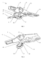
- the suspension according to the invention is in the general view in the position corresponding to the turning of the fork relative to the bolt in the position of use of the seat.
- the overall view is as to the stand-alone fork and in the Figure 3 is the detailed view of the suspension composition in the position corresponding to the recess of the fork relative to the bolt in the position of use of the seat.
- FIG. 1 and 3 is the representation of the seat suspension according to the invention, typically one of the pairs of front seat suspensions, which in the rear area with two other locks for attachment to the vehicle floor.
- the suspension is by a horizontal bolt 2, formed with support surface 22 for the fork 3. At the edges of the support surface 22 are stops 5, 5 ', which secure the fork 3 axially against an offset on the bolt, of the shape of a camshaft with dull, downwardly directed, vertex.
- the bolt 2 is including the stop 5, 5 'formed by plastic die-casting on a metal support 21 which is provided with openings for attachment to the vehicle floor.
- the complete contact 7, including the lead 71 in the connector 72 for connection to the electrical installation of the vehicle is inserted in the preparation of the bolt 2 in the mold and partially poured into the plastic of the bolt.
- the base part 31 which is formed at the lower part by means of a skirt 32, which merges in the rear area in the plate 33, which is used to attach the fork 3 to Seat serves.
- the front part of the fork is covered with a plastic cover 4, which forms the bearing surface 42 for the bolt 2 and in the lower part of the sliding surface 42, which facilitates installation of the seats and protects the fork 3 from damage.
- the enclosure 32 and thus also the cover 4 is curved in the front part, wherein the axis of curvature represents the axis of the attachment surface 41 and the pin axis 2.
- an electrical contact 8 is deposited in the cover 4.
- This electrical contact 8 is formed by a metal band, which is bent slightly upwards in the middle, and merges rearwardly into the supply line 81, immovably inserted in the holder 44 in the cover 4, protruding at the end of this and in the connector 82nd for connecting the seat electrical installation passes.
- the front free end 83 of the electrical contact 8 is enclosed in the holder 43 in the this can move with a pressure on the center of the electrical contact 8 with the electrical contact 7.
- the fork 3 is rotated with the rear part in the upright direction, because the rear locks of the seat are not closed, thus is the electrical contact 8 outside the electrical contact 7.
- the fork 3 is rotated, wherein the electrical contact 8 comes into contact with the electrical contact 7 and on the connector 82, the same potential as the connector 72 is supplied.
- the perfect contact of both connectors is guaranteed by the bias of the deformed electrical contact 8, the free end 83 is deeply inserted into the recess 44.
- the electrified suspension of the seat according to the invention can be used in all automobiles with removable seats equipped with any number of devices.
Landscapes
- Engineering & Computer Science (AREA)
- Aviation & Aerospace Engineering (AREA)
- Transportation (AREA)
- Mechanical Engineering (AREA)
- Seats For Vehicles (AREA)
Abstract
Description
- Die Erfindung betrifft die Sitzaufhängung, vor allem des herausnehmbaren Fahrzeugsitzes, mit einem Anschluss der Elektroinstallation des Sitzes an die Elektroinstallation des Fahrzeugs.
- Die Sitze moderner Fahrzeuge sind gegenwärtig mit verschiedenen elektrischen Einrichtungen z.B. einem Geber der Sicherheitsgurtbefestigung, der elektrischen Zündung der Sicherheitsgurtstraffer, einer Sitzheizung u.ä. ausgestattet. Bei nicht herausnehmbaren Sitzen ist der Anschluss dieser Systeme zum Bordnetz problemlos mittels der Kabel mit Verbindungsstecker durchführbar, jedoch bei herausnehmbaren Sitzes, welche in Mehrzweckfahrzeuge eingebaut werden, muss die elektrisch-leitfähige Verbindung mittels einer automatischen Verbindung bei einer Sitzinstallation im Fahrzeug und einer Entkoppelung bei der Demontage sichergestellt werden.
- Gegenwärtig sind mehrere Lösungen dieses Problems bekannt, z.B. die Lösung beschrieben im Dokument
US 6250703 B1 , in dem die Aufhängung des Sitzes mit einem Sicherungshaken versehen ist, welcher am Bolzen, angebracht in der Bodenaussparung, befestigt wird, wobei sich der elektrische Kontakt seitens des Fahrzeugs in dieser Aussparung und am Sitz am Sicherungshaken befindet. Bei der Sicherung des Hakens am Bolzen kommt es zur Berührung beider Kontakte. Nach der Demontage des Sitzes kann dieser Kontakt jedoch durch das Beladen von Ladegut im Bereich der Sitze beschädigt werden. Ein eventuelles Hängenbleiben des Kontakts, z.B. durch die Einwirkung von Korrosion, kann es zur unzureichenden Sicherung des Sitzes durch den Sicherungshaken kommen. - Eine weitere bekannte Lösung beschreibt das Dokument
DE 101 25 826 C1 . Der Sitz ist wiederum mit einer Einhängung mit Sicherungshaken versehen, welcher gegen den Bolzen im Boden einrastet, wobei dieser Bolzen aus Metall besteht und es zum leitenden Anschluss durch die Verbindung dieses Bolzens und des Sicherungshakens kommt. Die Sicherung des Sitzes und auch der elektrischen Verbindung ist in diesem Fall sicher und fähig größere Stromstärken und auch Daten zu übertragen, jede solche Einhängung ist jedoch in der Lage nur ein elektrisches Potential zu übertragen. - Die aufgeführten Unzulänglichkeiten beseitigt die elektrifizierte Sitzaufhängung des herausnehmbaren Fahrzeugsitzes laut der Erfindung, die eine elektrische Anbindung der Sitzelektroinstallation an die Elektroinstallation des Fahrzeugs sicherstellt. Die Aufhängung bildet ein Bolzen für die Befestigung am Fahrzeugboden, und eine Gabel zur Befestigung am Sitz und drehbar, aufsetzbar auf diesen Bolzen. Der Bolzen ist mindestens mit einem Anschlag zur Definition der axialen Gabelposition versehen, wobei mindestens an einem dieser Anschläge mindestens ein erster elektrischer Kontakt angebracht ist, der an die Elektroinstallation des Fahrzeugs angeschlossen werden kann. Die Gabel ist auf der entsprechenden Seite des angepassten Anschlags mindestens mit einem zweiten elektrischen Kontakt versehen, der an die Elektroinstallation des Sitzes angeschlossen werden kann. Der zweite elektrische Kontakt wird bei der Installation des Sitzes in das Fahrzeug automatisch in die elektrische Verbindung mit dem ersten Kontakt eingeschoben.
- Der erste elektrische Kontakt befindet sich mindestens am Umfangsbereich des Anschlags, mit dem Vorteil vor allem an dessen Unterseite, wo dieser gut gegen eine Beschädigung oder einen Kurzschluss gesichert ist. Der Anschlag mit Vorteil hat von der Sache her eine Form einer stumpfen Nockenwelle, mit einem nach unten gerichteten Scheitelpunkt. Der Bolzen einschließlich Anschlag ist mindestens teilweise aus elektrisch nicht leitfähigem Material gebildet, z.B. durch den Abguss von Plastik auf einem Metallträger. Der erste elektrische Kontakt und dessen Zuleitung in diesen Kunststoff wenigstens teilweise eingeschmolzen werden so, dass nur der für den Kontakt mit dem zweiten elektrischen Kontakt benötigte Teil freigelegt bleibt.
- Der untere Rand der Gabel ist mindestens an einer Seite mit einer Einfassung versehen, senkrecht zum Basisteil der Gabel, wobei sich der zweite elektrische Kontakt auf der oberen Seite der Einfassung befindet. Die Einfassung ist wenigstens im vorderen Teil gekrümmt, wobei die Krümmungsachse die Bolzenachse darstellt so, dass die Einfassung nach dem Einsetzte der Gabel auf den Bolzen und der Drehung, bei einem Einklappen und Ausklappen des Sitzes, sich mit einem konstanten Abstand um den Scheitelpunkt des Anschlags bewegt.
- Der vordere Teil der Gabel ist wenigstens teilweise mit einer geformten elektrisch nicht leitenden Abdeckung versehen, mittels dem der zweite elektrische Kontakt an der Gabel, bzw. an der Einfassung befestigt ist. Der zweite elektrische Kontakt kann flexibel angelegt sein, damit ein ausreichender Andruck in der Verbindung mit dem ersten elektrischen Kontakt sichergestellt ist und dadurch auch die Verbindungssicherheit während des Betriebs und Übertragungssicherheit besteht. In der vorteilhaften Ausführung ist der zweite elektrische Kontakt flexibel, welcher mittels der Zuleitung unbeweglich und durch das freie Ende verschiebbar in der Aussparung, gebildet durch die Abdeckung, angebracht ist.
- Es ist offenbar, dass wenn die elektrischen Kontakte an beiden Anschlägen des Bolzens angebracht sind, die Gabel mit einer Einfassung mit elektrischen Kontakten an beiden Seiten versehen sein kann. Weiter ist es offenbar, dass an einem Anschlag neben einander mehrere von einander unabhängige elektrische Kontakte angebracht werden können, gegenseitig axial versetzt, übereinstimmend mit der entsprechenden Anzahl elektrischer Kontakte an der Gabel. Die Anzahl dieser Kontakte und derer gegenseitiger Entfernungen ist lediglich durch die Breite des Anschlags bzw. der Gabeleinfassung und der Spielgröße der Gabel zwischen zwei Anschlägen, damit es im Betriebszustand nicht zum Kontakt der miteinander nicht übereinstimmenden Kontakte kommen kann, begrenzt. In den oben angeführten Fällen genügt dann die Anwendung von lediglich einer Aufhängung laut der Erfindung für die Übertragung von zwei oder mehr elektrischen Potentialen, wobei die zweite Aufhängung entsprechend der Ersten jedoch ohne Elektrifizierung umgesetzt werden kann.
- In der Abbildung Nr. 1 befindet sich die Aufhängung laut der Erfindung in der Gesamtansicht in der Position entsprechend der Eindrehung der Gabel gegenüber dem Bolzen in der Gebrauchsposition des Sitzes. In der Abbildung Nr. 2 ist die Gesamtansicht hinsichtlich der eigenständigen Gabel und in der
Abbildung 3 befindet sich die Detailansicht der Aufhängungszusammensetzung in der Position entsprechend der Eindrehung der Gabel gegenüber dem Bolzen in der Gebrauchsposition des Sitzes. - In der Abbildung Nr. 1 und 3 befindet sich die Darstellung der Sitzaufhängung laut der Erfindung, typisch eines der Paare der vorderen Sitzaufhängungen, welche im hinteren Bereich mit zwei weiteren Schlössern zur Befestigung an den Fahrzeugboden. Die Aufhängung wird durch einen waagerechten Bolzen 2, mit gebildeter Auflagefläche 22 für die Gabel 3. An den Rändern der Auflagefläche 22 bestehen Anschläge 5, 5', welche die Gabel 3 axial gegen einen Versatz auf dem Bolzen sichern, von der Form einer Nockenwelle mit stumpfem, nach unten gerichtetem, Scheitelpunkt. Der Bolzen 2 ist einschließlich des Anschlags 5, 5' durch Kunststoffdruckguss auf einem Metallträger 21 gebildet, der mit Öffnungen zur Befestigung am Fahrzeugboden versehen ist. Am Umfang des unteren Teils ist der Anschlag 5 mit einem elektrischen Kontakt 7 versehen, gebildet durch ein Metallband, welches durch die Zuleitung 71 zum Verbindungsstecker 72 angeschlossen ist. Der komplette Kontakt 7, einschließlich der Zuleitung 71 in des Verbindungssteckers 72 zum Anschluss an die Elektroinstallation des Fahrzeugs, wird bei der Anfertigung des Bolzens 2 in die Form eingelegt und teilweise in den Kunststoff des Bolzens eingegossen.
- In der Abbildung Nr. 2 in der Darstellung der nach vorn geöffneten Gabel 3 wird durch den Basisteil 31 gebildet, die am unteren Teil mittels einer Einfassung 32 gebildet wird, welche im hinteren Bereich in die Platte 33 übergeht, welche zur Befestigung der Gabel 3 zum Sitz dient. Der vordere Teil der Gabel ist mit einer Plastikabdeckung 4 abgedeckt, welche die Auflagefläche 42 für den Bolzen 2 und im unteren Teil der Gleitfläche 42 bildet, die eine Installation der Sitze erleichtert und die Gabel 3 vor einer Beschädigung schützt. Die Einfassung 32 und damit auch die Abdeckung 4 ist im vorderen Teil gekrümmt, wobei die Krümmungsachse die Achse der Aufsatzfläche 41 bzw. die Bolzenachse 2 darstellt. Auf der Seite des vorderen Einfassungsbereichs 32, ist in der Abdeckung 4 ein elektrischer Kontakt 8 hinterlegt. Dieser elektrische Kontakt 8 wird durch ein Metallband gebildet, welches in der Mitte leicht nach oben gebogen ist, und nach hinten in die Zuleitung 81 übergeht, unbeweglich eingeführt in der Halterung 44 in der Abdeckung 4, an deren Ende dieses herausragt und in den Verbindungsstecker 82 für den Anschluss der Sitzelektroinstallation übergeht. Das vordere freie Ende 83 des Elektrokontakts 8 ist in die Halterung 43 eingefasst in der sich dieses bei einem Druck auf die Mitte des elektrischen Kontakts 8 mit dem elektrischen Kontakt 7 bewegen kann.
- Bei der Montage des Sitzes, nach dem Einsatz der Gabel 3 auf den Bolzen 2 setzen die Auflagenflächen 42 und 22 aufeinander auf, wobei die Gabel 3 mit dem hinteren Teil in aufrechter Richtung gedreht wird, denn die hinteren Schlösser des Sitzes sind nicht verschlossen, somit befindet sich der elektrische Kontakt 8 außerhalb der elektrischen Kontakts 7. Nach dem Abklappen des Sitzes in die Gebrauchsposition wird die Gabel 3 gedreht, wobei der elektrische Kontakt 8 in den Kontakt mit dem elektrischen Kontakt 7 kommt und auf den Verbindungsstecker 82 dasselbe Potential wie zum Verbindungsstecker 72 zugeführt wird. Die perfekte Berührung beider Verbindungsstecker wird durch die Vorspannung des deformierten elektrischen Kontakts 8 garantiert, dessen freies Ende 83 tiefe in die Aussparung 44 eingeschoben ist. Nach der Entriegelung der hinteren Sitzschlösser und dem Umklappen des Sitzes nach oben um die Bolzenachse in die nicht gebrauchsfähige Position wird der elektrische Kontakt 8 nach außen gedreht und aus der Verbindung mit dem Kontakt 7 gelöst und die Verbindung ist damit unterbrochen.
- Die elektrifizierte Aufhängung des Sitzes laut der Erfindung, kann bei allen Automobilen mit herausnehmbaren Sitzen, ausgestattet mit einer beliebigen Anzahl von Einrichtungen, Verwendung finden.
Claims (10)
- Die Erfindung der elektrifizierten Sitzaufhängung (1), vor allem des herausnehmbaren Fahrzeugsitzes, mit einem Anschluss der Elektroinstallation des Sitzes an die Elektroinstallation des Fahrzeugs beinhaltend:- den Bolzen (2) fixierbar an den Fahrzeugboden,- die Gabel (3) fixierbar zum Sitz und drehbar aufsetzbar auf den Bolzen (3),- den ersten elektrischen Kontakt (7) anschließbar zur Elektroinstallation des Fahrzeugs,- den zweiten elektrischen Kontakt (8) anschließbar an die Elektroinstallation des Sitzes, wobei dieser zweite elektrische Kontakt (8) sich automatisch in die elektrisch leitende Verbindung mit dem ersten Kontakt (7) bei der Installation des Sitzes in das Fahrzeug einschiebt,mit der Ausprägung, der Bolzen (2) mindestens mit einem Anschlag (5, 5') für die axiale Positionierung der Gabel (3) versehen ist, wobei mindestens an einem der Anschläge (5, 5') mindestens ein ester elektrischer Kontakt (7) angebracht ist, und die Gabel (3) mindestens mit einem zweiten elektrischen Kontakt (8) auf der Seite des zugehörigen Anschlags (5, 5') versehen ist.
- Die elektrifizierte Sitzaufhängung (1) laut der Anforderung 1 kennzeichne t sich dadurch aus, dass der erste elektrische Kontakt (7) sich mindestens am Umfangsteil des Anschlags (5, 5'), vor allem an dessen Unterseite befindet.
- Die elektrifizierte Sitzaufhängung (1) laut der Anforderung 1 oder 2 kennzei chnet sich dadurch aus, dass der Anschlag (5, 5') die Form einer stumpfen Nockenwelle mit nach unten gerichtetem Scheitelpunkt voreweist.
- Die elektrifizierte Sitzaufhängung (1) laut einer der vorangegangenen Anforderungen kennzeichnet sich dadurch aus, dass der Bolzen (3) einschließlich Anschlag (5, 5') wenigstens teilweise aus Kunststoff gebildet wird, in den der erste Kontakt (7) und / oder die Zuleitung (71) wenigstens teilweise eingeschmolzen sind.
- Die elektrifizierte Sitzaufhängung (1) laut einer der vorangegangenen Anforderungen kennzeichnet sich dadurch aus, dass der untere Rand der Gabel (3) an einer Seite mit einer Einfassung (32) versehen ist, senkrecht zum vertikalen Basisteil (31) der Gabel (3), wobei sich der zweite elektrische Kontakt mindestens an der Oberseite dieser Einfassung (32) befindet.
- Die elektrifizierte Sitzaufhängung (1) laut der Anforderung 5 kennzeichnet sich dadurch aus, dass die Einfassung (32) mindestens im vorderen bereich gekrümmt ist, wobei die Krümmungsachse die Bolzenachse (3) darstellt.
- Die elektrifizierte Sitzaufhängung (1) laut einer der vorangegangenen Anforderungen kennzeichnet sich dadurch aus, dass der vordere Bereich der Gabel (3) mindestens teilweise mit einer geformten elektrisch nicht leitenden Abdeckung (4) versehen ist, mittels dem der zweite elektrische Kontakt (8) zur Gabel (3) befestigt ist.
- Die elektrifizierte Sitzaufhängung (1) laut einer der vorangegangenen Anforderungen kennzeichnet sich dadurch aus, dass der zweite elektrische Kontakt (8) flexibel ist oder flexibel befestigt ist.
- Die elektrifizierte Sitzaufhängung (1) laut der Anforderung 7 kennzeichne t sich dadurch aus, dass der zweite elektrische Kontakt (8) mit der Zuleitung (81) unbeweglich in der Aussparung (44) in der Abdeckung (4)und mit dem freien Ende (83) verschiebbar in der Aussparung (43) gebildet durch die Abdeckung (4) befestigt ist.
- Das System der elektrifizierten Sitzaufhängung kennzeichnet sich da durch aus, dass der Sitz im vorderen Teil mindestens mit einem Aufhängungsteil laut der vorangegangenen Anforderungen versehen sein muss.
Applications Claiming Priority (1)
| Application Number | Priority Date | Filing Date | Title |
|---|---|---|---|
| CZ20060826A CZ301897B6 (cs) | 2006-12-22 | 2006-12-22 | Elektrifikovaný záves sedadla |
Publications (3)
| Publication Number | Publication Date |
|---|---|
| EP1935706A2 true EP1935706A2 (de) | 2008-06-25 |
| EP1935706A3 EP1935706A3 (de) | 2011-01-19 |
| EP1935706B1 EP1935706B1 (de) | 2012-10-03 |
Family
ID=39144548
Family Applications (1)
| Application Number | Title | Priority Date | Filing Date |
|---|---|---|---|
| EP07466028A Ceased EP1935706B1 (de) | 2006-12-22 | 2007-12-20 | Elektrifizierte Sitzbefestigung |
Country Status (2)
| Country | Link |
|---|---|
| EP (1) | EP1935706B1 (de) |
| CZ (1) | CZ301897B6 (de) |
Citations (2)
| Publication number | Priority date | Publication date | Assignee | Title |
|---|---|---|---|---|
| US6250703B1 (en) | 1998-04-30 | 2001-06-26 | Magna Seating Systems Inc. | Automotive removable power seat |
| DE10125826C1 (de) | 2001-05-26 | 2002-11-07 | Bosch Gmbh Robert | Elektrische Verbindung zu einem herausnehmbaren Fahrzeugsitz |
Family Cites Families (4)
| Publication number | Priority date | Publication date | Assignee | Title |
|---|---|---|---|---|
| CZ282560B6 (cs) * | 1993-05-21 | 1997-08-13 | ŠKODA AUTO a.s. | Sklopitelné sedadlo pro užitkové provedení osobních automobilů |
| FR2776591B1 (fr) * | 1998-03-25 | 2000-05-05 | Peugeot | Dispositif d'alimentation electrique des moyens de commande des fonctions d'un siege demontable de vehicule, notamment automobile |
| DE10352547B4 (de) * | 2003-11-11 | 2017-04-06 | Rosenberger Hochfrequenztechnik Gmbh & Co. Kg | System zur elektrischen Verbindung eines Sitzes, insbesondere eines Fahrzeugsitzes |
| EP1655168A1 (de) * | 2004-11-04 | 2006-05-10 | Delphi Technologies, Inc. | Elektrischer Steckverbinder |
-
2006
- 2006-12-22 CZ CZ20060826A patent/CZ301897B6/cs unknown
-
2007
- 2007-12-20 EP EP07466028A patent/EP1935706B1/de not_active Ceased
Patent Citations (2)
| Publication number | Priority date | Publication date | Assignee | Title |
|---|---|---|---|---|
| US6250703B1 (en) | 1998-04-30 | 2001-06-26 | Magna Seating Systems Inc. | Automotive removable power seat |
| DE10125826C1 (de) | 2001-05-26 | 2002-11-07 | Bosch Gmbh Robert | Elektrische Verbindung zu einem herausnehmbaren Fahrzeugsitz |
Also Published As
| Publication number | Publication date |
|---|---|
| EP1935706B1 (de) | 2012-10-03 |
| CZ301897B6 (cs) | 2010-07-21 |
| CZ2006826A3 (cs) | 2008-07-02 |
| EP1935706A3 (de) | 2011-01-19 |
Similar Documents
| Publication | Publication Date | Title |
|---|---|---|
| DE102011084883B4 (de) | System aus einem Sitzgestellelement und einem Befestigungselement für eine elektrische Leitung eines Fahrzeugsitzes | |
| DE4444122C1 (de) | Anzeigevorrichtung zur Signalisierung der Nichtverriegelung einer umklappbaren Rückenlehne eines Fahrzeugsitzes | |
| DE4227383A1 (de) | Drehbare elektrische verbindungsanordnung | |
| DE60106194T2 (de) | Installationsgerät | |
| DE102007050421A1 (de) | Mit Kabel ausgestatteter Verbinder | |
| DE102009044701A1 (de) | Einberührungs-Bremsleuchtenschalter eines Fahrzeuges | |
| DE60126631T2 (de) | Vorrichtung zur halterung von crimpzonen einer flexiblen schaltung in einem elektrischen verbinder und so ausgerüsteter verbinder | |
| DE69306478T2 (de) | Verbesserungen bezüglich des Anschluss elementes eines Verbinders für Oberflächenmontage | |
| DE202010003686U1 (de) | Anhängerkupplung | |
| DE102011002135A1 (de) | Steckerelement mit zweiter Kontaktsicherung | |
| DE2911464A1 (de) | Sonnenblende fuer kraftfahrzeuge | |
| EP1935706B1 (de) | Elektrifizierte Sitzbefestigung | |
| DE112016006333B4 (de) | Gehäusesicherungseinheit für ein fahrzeug und gehäuse zur substratunterbringung | |
| DE102019104127A1 (de) | Elektronische Vorrichtung und Shuntwiderstandsbefestigung | |
| DE4203133C2 (de) | Elektrische Verbindungseinrichtung | |
| DE102008031967A1 (de) | Mit einem elektronischen Teil ausgestattete Einheit | |
| DE2641258A1 (de) | Anschlussvorrichtung mit stecksockel fuer elektrische bauteile | |
| DE202004004619U1 (de) | Mechanische Schließvorrichtung für Elektrosteckergehäuse | |
| EP2456016B1 (de) | Verriegelungsanordnung für eine Steckervorrichtung einer elektronischen Baugruppe in der Automatisierungstechnik | |
| DE102009050932A1 (de) | Anhängerkupplungseinrichtung für einen Kraftwagen | |
| DE69313133T2 (de) | Antennenbefestigung auf fahrzeugscheiben | |
| DE10232649A1 (de) | Abdeckung für ein Verhindern eines Eintretens von Wasser in einen Anschlußblock, Anschlußblock, welcher damit versehen ist, und Verfahren zum Montieren eines Anschlußblocks | |
| DE9015364U1 (de) | Kabelhalterung | |
| DE4035856A1 (de) | Armlehne fuer einen kraftfahrzeugsitz | |
| EP3791448B1 (de) | Rechtecksteckverbinder für kontaktträger |
Legal Events
| Date | Code | Title | Description |
|---|---|---|---|
| PUAI | Public reference made under article 153(3) epc to a published international application that has entered the european phase |
Free format text: ORIGINAL CODE: 0009012 |
|
| AK | Designated contracting states |
Kind code of ref document: A2 Designated state(s): AT BE BG CH CY CZ DE DK EE ES FI FR GB GR HU IE IS IT LI LT LU LV MC MT NL PL PT RO SE SI SK TR |
|
| AX | Request for extension of the european patent |
Extension state: AL BA HR MK RS |
|
| PUAL | Search report despatched |
Free format text: ORIGINAL CODE: 0009013 |
|
| AK | Designated contracting states |
Kind code of ref document: A3 Designated state(s): AT BE BG CH CY CZ DE DK EE ES FI FR GB GR HU IE IS IT LI LT LU LV MC MT NL PL PT RO SE SI SK TR |
|
| AX | Request for extension of the european patent |
Extension state: AL BA HR MK RS |
|
| 17P | Request for examination filed |
Effective date: 20110719 |
|
| AKX | Designation fees paid |
Designated state(s): DE ES FR GB IT SE |
|
| GRAP | Despatch of communication of intention to grant a patent |
Free format text: ORIGINAL CODE: EPIDOSNIGR1 |
|
| GRAS | Grant fee paid |
Free format text: ORIGINAL CODE: EPIDOSNIGR3 |
|
| GRAA | (expected) grant |
Free format text: ORIGINAL CODE: 0009210 |
|
| AK | Designated contracting states |
Kind code of ref document: B1 Designated state(s): DE ES FR GB IT SE |
|
| REG | Reference to a national code |
Ref country code: GB Ref legal event code: FG4D Free format text: NOT ENGLISH |
|
| REG | Reference to a national code |
Ref country code: DE Ref legal event code: R096 Ref document number: 502007010624 Country of ref document: DE Effective date: 20121129 |
|
| PG25 | Lapsed in a contracting state [announced via postgrant information from national office to epo] |
Ref country code: SE Free format text: LAPSE BECAUSE OF FAILURE TO SUBMIT A TRANSLATION OF THE DESCRIPTION OR TO PAY THE FEE WITHIN THE PRESCRIBED TIME-LIMIT Effective date: 20121003 Ref country code: ES Free format text: LAPSE BECAUSE OF FAILURE TO SUBMIT A TRANSLATION OF THE DESCRIPTION OR TO PAY THE FEE WITHIN THE PRESCRIBED TIME-LIMIT Effective date: 20130114 |
|
| PLBE | No opposition filed within time limit |
Free format text: ORIGINAL CODE: 0009261 |
|
| STAA | Information on the status of an ep patent application or granted ep patent |
Free format text: STATUS: NO OPPOSITION FILED WITHIN TIME LIMIT |
|
| PG25 | Lapsed in a contracting state [announced via postgrant information from national office to epo] |
Ref country code: IT Free format text: LAPSE BECAUSE OF FAILURE TO SUBMIT A TRANSLATION OF THE DESCRIPTION OR TO PAY THE FEE WITHIN THE PRESCRIBED TIME-LIMIT Effective date: 20121003 |
|
| 26N | No opposition filed |
Effective date: 20130704 |
|
| REG | Reference to a national code |
Ref country code: DE Ref legal event code: R097 Ref document number: 502007010624 Country of ref document: DE Effective date: 20130704 |
|
| REG | Reference to a national code |
Ref country code: FR Ref legal event code: PLFP Year of fee payment: 9 |
|
| REG | Reference to a national code |
Ref country code: FR Ref legal event code: PLFP Year of fee payment: 10 |
|
| REG | Reference to a national code |
Ref country code: FR Ref legal event code: PLFP Year of fee payment: 11 |
|
| P01 | Opt-out of the competence of the unified patent court (upc) registered |
Effective date: 20230626 |
|
| PGFP | Annual fee paid to national office [announced via postgrant information from national office to epo] |
Ref country code: FR Payment date: 20230829 Year of fee payment: 17 |
|
| PGFP | Annual fee paid to national office [announced via postgrant information from national office to epo] |
Ref country code: GB Payment date: 20231024 Year of fee payment: 17 |
|
| PGFP | Annual fee paid to national office [announced via postgrant information from national office to epo] |
Ref country code: DE Payment date: 20230828 Year of fee payment: 17 |
|
| REG | Reference to a national code |
Ref country code: DE Ref legal event code: R119 Ref document number: 502007010624 Country of ref document: DE |
|
| GBPC | Gb: european patent ceased through non-payment of renewal fee |
Effective date: 20241220 |
|
| PG25 | Lapsed in a contracting state [announced via postgrant information from national office to epo] |
Ref country code: DE Free format text: LAPSE BECAUSE OF NON-PAYMENT OF DUE FEES Effective date: 20250701 |
|
| PG25 | Lapsed in a contracting state [announced via postgrant information from national office to epo] |
Ref country code: GB Free format text: LAPSE BECAUSE OF NON-PAYMENT OF DUE FEES Effective date: 20241220 |
|
| PG25 | Lapsed in a contracting state [announced via postgrant information from national office to epo] |
Ref country code: FR Free format text: LAPSE BECAUSE OF NON-PAYMENT OF DUE FEES Effective date: 20241231 |