EP1935706A2 - Fixation de siège électrifiée - Google Patents
Fixation de siège électrifiée Download PDFInfo
- Publication number
- EP1935706A2 EP1935706A2 EP07466028A EP07466028A EP1935706A2 EP 1935706 A2 EP1935706 A2 EP 1935706A2 EP 07466028 A EP07466028 A EP 07466028A EP 07466028 A EP07466028 A EP 07466028A EP 1935706 A2 EP1935706 A2 EP 1935706A2
- Authority
- EP
- European Patent Office
- Prior art keywords
- seat
- electrical contact
- fork
- electrified
- electrical
- Prior art date
- Legal status (The legal status is an assumption and is not a legal conclusion. Google has not performed a legal analysis and makes no representation as to the accuracy of the status listed.)
- Granted
Links
Images

Classifications
-
- B—PERFORMING OPERATIONS; TRANSPORTING
- B60—VEHICLES IN GENERAL
- B60N—SEATS SPECIALLY ADAPTED FOR VEHICLES; VEHICLE PASSENGER ACCOMMODATION NOT OTHERWISE PROVIDED FOR
- B60N2/00—Seats specially adapted for vehicles; Arrangement or mounting of seats in vehicles
- B60N2/005—Arrangement or mounting of seats in vehicles, e.g. dismountable auxiliary seats
- B60N2/015—Attaching seats directly to vehicle chassis
- B60N2/01508—Attaching seats directly to vehicle chassis using quick release attachments
- B60N2/01516—Attaching seats directly to vehicle chassis using quick release attachments with locking mechanisms
- B60N2/01583—Attaching seats directly to vehicle chassis using quick release attachments with locking mechanisms locking on transversal elements on the vehicle floor or rail, e.g. transversal rods
-
- B—PERFORMING OPERATIONS; TRANSPORTING
- B60—VEHICLES IN GENERAL
- B60N—SEATS SPECIALLY ADAPTED FOR VEHICLES; VEHICLE PASSENGER ACCOMMODATION NOT OTHERWISE PROVIDED FOR
- B60N2/00—Seats specially adapted for vehicles; Arrangement or mounting of seats in vehicles
- B60N2/02—Seats specially adapted for vehicles; Arrangement or mounting of seats in vehicles the seat or part thereof being movable, e.g. adjustable
- B60N2/0224—Non-manual adjustments, e.g. with electrical operation
-
- B—PERFORMING OPERATIONS; TRANSPORTING
- B60—VEHICLES IN GENERAL
- B60N—SEATS SPECIALLY ADAPTED FOR VEHICLES; VEHICLE PASSENGER ACCOMMODATION NOT OTHERWISE PROVIDED FOR
- B60N2/00—Seats specially adapted for vehicles; Arrangement or mounting of seats in vehicles
- B60N2/02—Seats specially adapted for vehicles; Arrangement or mounting of seats in vehicles the seat or part thereof being movable, e.g. adjustable
- B60N2/0224—Non-manual adjustments, e.g. with electrical operation
- B60N2/0244—Non-manual adjustments, e.g. with electrical operation with logic circuits
- B60N2/0264—Non-manual adjustments, e.g. with electrical operation with logic circuits characterised by the type of electrical connection, e.g. wiring, plugs or USB
Definitions
- the invention relates to the seat suspension, especially the removable vehicle seat, with a connection of the electrical installation of the seat to the electrical installation of the vehicle.
- the seats of modern vehicles are presently equipped with various electrical devices, e.g. a safety belt fastener sender, the electric ignition of the seatbelt pretensioner, a seat heater and the like fitted.
- various electrical devices e.g. a safety belt fastener sender, the electric ignition of the seatbelt pretensioner, a seat heater and the like fitted.
- the connection of these systems to the electrical system is easily feasible by means of cables with connector, but with removable seat, which are installed in multi-purpose vehicles, the electrically conductive connection by means of an automatic connection in a seat installation in the vehicle and a decoupling in the Disassembly can be ensured.
- the suspension forms a bolt for attachment to the vehicle floor, and a fork for attachment to the seat and rotatable, attachable to this bolt.
- the bolt is provided with at least one stop for defining the axial fork position, wherein at least one of these stops at least a first electrical contact is attached, which can be connected to the electrical installation of the vehicle.
- the fork is provided on the corresponding side of the matched stop with at least a second electrical contact that can be connected to the electrical installation of the seat. The second electrical contact is automatically inserted in the installation of the seat in the vehicle in the electrical connection with the first contact.
- the first electrical contact is located at least on the peripheral region of the stop, with the advantage especially on its underside, where it is well secured against damage or short circuit.
- the stop advantageously has a shape of a blunt camshaft, with a downwardly directed vertex.
- the pin including stopper is formed at least partially of electrically non-conductive material, e.g. through the casting of plastic on a metal support. The first electrical contact and its lead in this plastic are at least partially melted so that only the required for contact with the second electrical contact part remains exposed.
- the lower edge of the fork is provided with a skirt at least on one side, perpendicular to the base of the fork, with the second electrical contact on the upper side of the skirt.
- the skirt is curved at least in the front part, the axis of curvature representing the pin axis, such that after insertion of the fork onto the pin and the rotation, when folding and unfolding the seat, moves at a constant distance around the vertex of the stop.
- the front part of the fork is at least partially provided with a shaped electrically non-conductive cover, by means of which the second electrical contact is attached to the fork, or to the enclosure.
- the second electrical contact can be applied flexibly, so that a sufficient pressure in the connection with the first electrical contact is ensured and thereby also the connection security during operation and transmission security exists.
- the second electrical contact is flexible, which is immovable by means of the lead and slidably mounted in the recess formed by the cover by the free end.
- the fork can be provided with a skirt with electrical contacts on both sides. Further, it is apparent that a plurality of mutually independent electrical contacts can be attached to a stop next to each other, axially offset, coincident with the corresponding number of electrical contacts on the fork. The number of these contacts and their mutual distances is limited only by the width of the stop or the fork mount and the game size of the fork between two stops so that it can not come into contact with the mismatching contacts in the operating state. In the above cases, then, the application of only one suspension according to the invention for the transmission of two or more electrical potentials is sufficient, but the second suspension according to the first can be implemented without electrification.
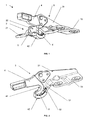
- the suspension according to the invention is in the general view in the position corresponding to the turning of the fork relative to the bolt in the position of use of the seat.
- the overall view is as to the stand-alone fork and in the Figure 3 is the detailed view of the suspension composition in the position corresponding to the recess of the fork relative to the bolt in the position of use of the seat.
- FIG. 1 and 3 is the representation of the seat suspension according to the invention, typically one of the pairs of front seat suspensions, which in the rear area with two other locks for attachment to the vehicle floor.
- the suspension is by a horizontal bolt 2, formed with support surface 22 for the fork 3. At the edges of the support surface 22 are stops 5, 5 ', which secure the fork 3 axially against an offset on the bolt, of the shape of a camshaft with dull, downwardly directed, vertex.
- the bolt 2 is including the stop 5, 5 'formed by plastic die-casting on a metal support 21 which is provided with openings for attachment to the vehicle floor.
- the complete contact 7, including the lead 71 in the connector 72 for connection to the electrical installation of the vehicle is inserted in the preparation of the bolt 2 in the mold and partially poured into the plastic of the bolt.
- the base part 31 which is formed at the lower part by means of a skirt 32, which merges in the rear area in the plate 33, which is used to attach the fork 3 to Seat serves.
- the front part of the fork is covered with a plastic cover 4, which forms the bearing surface 42 for the bolt 2 and in the lower part of the sliding surface 42, which facilitates installation of the seats and protects the fork 3 from damage.
- the enclosure 32 and thus also the cover 4 is curved in the front part, wherein the axis of curvature represents the axis of the attachment surface 41 and the pin axis 2.
- an electrical contact 8 is deposited in the cover 4.
- This electrical contact 8 is formed by a metal band, which is bent slightly upwards in the middle, and merges rearwardly into the supply line 81, immovably inserted in the holder 44 in the cover 4, protruding at the end of this and in the connector 82nd for connecting the seat electrical installation passes.
- the front free end 83 of the electrical contact 8 is enclosed in the holder 43 in the this can move with a pressure on the center of the electrical contact 8 with the electrical contact 7.
- the fork 3 is rotated with the rear part in the upright direction, because the rear locks of the seat are not closed, thus is the electrical contact 8 outside the electrical contact 7.
- the fork 3 is rotated, wherein the electrical contact 8 comes into contact with the electrical contact 7 and on the connector 82, the same potential as the connector 72 is supplied.
- the perfect contact of both connectors is guaranteed by the bias of the deformed electrical contact 8, the free end 83 is deeply inserted into the recess 44.
- the electrified suspension of the seat according to the invention can be used in all automobiles with removable seats equipped with any number of devices.
Landscapes
- Engineering & Computer Science (AREA)
- Aviation & Aerospace Engineering (AREA)
- Transportation (AREA)
- Mechanical Engineering (AREA)
- Seats For Vehicles (AREA)
Applications Claiming Priority (1)
| Application Number | Priority Date | Filing Date | Title |
|---|---|---|---|
| CZ20060826A CZ301897B6 (cs) | 2006-12-22 | 2006-12-22 | Elektrifikovaný záves sedadla |
Publications (3)
| Publication Number | Publication Date |
|---|---|
| EP1935706A2 true EP1935706A2 (fr) | 2008-06-25 |
| EP1935706A3 EP1935706A3 (fr) | 2011-01-19 |
| EP1935706B1 EP1935706B1 (fr) | 2012-10-03 |
Family
ID=39144548
Family Applications (1)
| Application Number | Title | Priority Date | Filing Date |
|---|---|---|---|
| EP07466028A Ceased EP1935706B1 (fr) | 2006-12-22 | 2007-12-20 | Fixation de siège électrifiée |
Country Status (2)
| Country | Link |
|---|---|
| EP (1) | EP1935706B1 (fr) |
| CZ (1) | CZ301897B6 (fr) |
Citations (2)
| Publication number | Priority date | Publication date | Assignee | Title |
|---|---|---|---|---|
| US6250703B1 (en) | 1998-04-30 | 2001-06-26 | Magna Seating Systems Inc. | Automotive removable power seat |
| DE10125826C1 (de) | 2001-05-26 | 2002-11-07 | Bosch Gmbh Robert | Elektrische Verbindung zu einem herausnehmbaren Fahrzeugsitz |
Family Cites Families (4)
| Publication number | Priority date | Publication date | Assignee | Title |
|---|---|---|---|---|
| CZ282560B6 (cs) * | 1993-05-21 | 1997-08-13 | ŠKODA AUTO a.s. | Sklopitelné sedadlo pro užitkové provedení osobních automobilů |
| FR2776591B1 (fr) * | 1998-03-25 | 2000-05-05 | Peugeot | Dispositif d'alimentation electrique des moyens de commande des fonctions d'un siege demontable de vehicule, notamment automobile |
| DE10352547B4 (de) * | 2003-11-11 | 2017-04-06 | Rosenberger Hochfrequenztechnik Gmbh & Co. Kg | System zur elektrischen Verbindung eines Sitzes, insbesondere eines Fahrzeugsitzes |
| EP1655168A1 (fr) * | 2004-11-04 | 2006-05-10 | Delphi Technologies, Inc. | Connecteur électrique |
-
2006
- 2006-12-22 CZ CZ20060826A patent/CZ301897B6/cs unknown
-
2007
- 2007-12-20 EP EP07466028A patent/EP1935706B1/fr not_active Ceased
Patent Citations (2)
| Publication number | Priority date | Publication date | Assignee | Title |
|---|---|---|---|---|
| US6250703B1 (en) | 1998-04-30 | 2001-06-26 | Magna Seating Systems Inc. | Automotive removable power seat |
| DE10125826C1 (de) | 2001-05-26 | 2002-11-07 | Bosch Gmbh Robert | Elektrische Verbindung zu einem herausnehmbaren Fahrzeugsitz |
Also Published As
| Publication number | Publication date |
|---|---|
| EP1935706B1 (fr) | 2012-10-03 |
| CZ301897B6 (cs) | 2010-07-21 |
| CZ2006826A3 (cs) | 2008-07-02 |
| EP1935706A3 (fr) | 2011-01-19 |
Similar Documents
| Publication | Publication Date | Title |
|---|---|---|
| DE102011084883B4 (de) | System aus einem Sitzgestellelement und einem Befestigungselement für eine elektrische Leitung eines Fahrzeugsitzes | |
| DE4444122C1 (de) | Anzeigevorrichtung zur Signalisierung der Nichtverriegelung einer umklappbaren Rückenlehne eines Fahrzeugsitzes | |
| DE4227383A1 (de) | Drehbare elektrische verbindungsanordnung | |
| DE60106194T2 (de) | Installationsgerät | |
| DE102007050421A1 (de) | Mit Kabel ausgestatteter Verbinder | |
| DE102009044701A1 (de) | Einberührungs-Bremsleuchtenschalter eines Fahrzeuges | |
| DE60126631T2 (de) | Vorrichtung zur halterung von crimpzonen einer flexiblen schaltung in einem elektrischen verbinder und so ausgerüsteter verbinder | |
| DE69306478T2 (de) | Verbesserungen bezüglich des Anschluss elementes eines Verbinders für Oberflächenmontage | |
| DE202010003686U1 (de) | Anhängerkupplung | |
| DE102011002135A1 (de) | Steckerelement mit zweiter Kontaktsicherung | |
| DE2911464A1 (de) | Sonnenblende fuer kraftfahrzeuge | |
| EP1935706B1 (fr) | Fixation de siège électrifiée | |
| DE112016006333B4 (de) | Gehäusesicherungseinheit für ein fahrzeug und gehäuse zur substratunterbringung | |
| DE102019104127A1 (de) | Elektronische Vorrichtung und Shuntwiderstandsbefestigung | |
| DE4203133C2 (de) | Elektrische Verbindungseinrichtung | |
| DE102008031967A1 (de) | Mit einem elektronischen Teil ausgestattete Einheit | |
| DE2641258A1 (de) | Anschlussvorrichtung mit stecksockel fuer elektrische bauteile | |
| DE202004004619U1 (de) | Mechanische Schließvorrichtung für Elektrosteckergehäuse | |
| EP2456016B1 (fr) | Agencement de verrouillage pour un dispositif de connecteur d'un composant électronique issu de la technique d'automatisation | |
| DE102009050932A1 (de) | Anhängerkupplungseinrichtung für einen Kraftwagen | |
| DE69313133T2 (de) | Antennenbefestigung auf fahrzeugscheiben | |
| DE10232649A1 (de) | Abdeckung für ein Verhindern eines Eintretens von Wasser in einen Anschlußblock, Anschlußblock, welcher damit versehen ist, und Verfahren zum Montieren eines Anschlußblocks | |
| DE9015364U1 (de) | Kabelhalterung | |
| DE4035856A1 (de) | Armlehne fuer einen kraftfahrzeugsitz | |
| EP3791448B1 (fr) | Connecteur rectangulaire pour porte-contacts |
Legal Events
| Date | Code | Title | Description |
|---|---|---|---|
| PUAI | Public reference made under article 153(3) epc to a published international application that has entered the european phase |
Free format text: ORIGINAL CODE: 0009012 |
|
| AK | Designated contracting states |
Kind code of ref document: A2 Designated state(s): AT BE BG CH CY CZ DE DK EE ES FI FR GB GR HU IE IS IT LI LT LU LV MC MT NL PL PT RO SE SI SK TR |
|
| AX | Request for extension of the european patent |
Extension state: AL BA HR MK RS |
|
| PUAL | Search report despatched |
Free format text: ORIGINAL CODE: 0009013 |
|
| AK | Designated contracting states |
Kind code of ref document: A3 Designated state(s): AT BE BG CH CY CZ DE DK EE ES FI FR GB GR HU IE IS IT LI LT LU LV MC MT NL PL PT RO SE SI SK TR |
|
| AX | Request for extension of the european patent |
Extension state: AL BA HR MK RS |
|
| 17P | Request for examination filed |
Effective date: 20110719 |
|
| AKX | Designation fees paid |
Designated state(s): DE ES FR GB IT SE |
|
| GRAP | Despatch of communication of intention to grant a patent |
Free format text: ORIGINAL CODE: EPIDOSNIGR1 |
|
| GRAS | Grant fee paid |
Free format text: ORIGINAL CODE: EPIDOSNIGR3 |
|
| GRAA | (expected) grant |
Free format text: ORIGINAL CODE: 0009210 |
|
| AK | Designated contracting states |
Kind code of ref document: B1 Designated state(s): DE ES FR GB IT SE |
|
| REG | Reference to a national code |
Ref country code: GB Ref legal event code: FG4D Free format text: NOT ENGLISH |
|
| REG | Reference to a national code |
Ref country code: DE Ref legal event code: R096 Ref document number: 502007010624 Country of ref document: DE Effective date: 20121129 |
|
| PG25 | Lapsed in a contracting state [announced via postgrant information from national office to epo] |
Ref country code: SE Free format text: LAPSE BECAUSE OF FAILURE TO SUBMIT A TRANSLATION OF THE DESCRIPTION OR TO PAY THE FEE WITHIN THE PRESCRIBED TIME-LIMIT Effective date: 20121003 Ref country code: ES Free format text: LAPSE BECAUSE OF FAILURE TO SUBMIT A TRANSLATION OF THE DESCRIPTION OR TO PAY THE FEE WITHIN THE PRESCRIBED TIME-LIMIT Effective date: 20130114 |
|
| PLBE | No opposition filed within time limit |
Free format text: ORIGINAL CODE: 0009261 |
|
| STAA | Information on the status of an ep patent application or granted ep patent |
Free format text: STATUS: NO OPPOSITION FILED WITHIN TIME LIMIT |
|
| PG25 | Lapsed in a contracting state [announced via postgrant information from national office to epo] |
Ref country code: IT Free format text: LAPSE BECAUSE OF FAILURE TO SUBMIT A TRANSLATION OF THE DESCRIPTION OR TO PAY THE FEE WITHIN THE PRESCRIBED TIME-LIMIT Effective date: 20121003 |
|
| 26N | No opposition filed |
Effective date: 20130704 |
|
| REG | Reference to a national code |
Ref country code: DE Ref legal event code: R097 Ref document number: 502007010624 Country of ref document: DE Effective date: 20130704 |
|
| REG | Reference to a national code |
Ref country code: FR Ref legal event code: PLFP Year of fee payment: 9 |
|
| REG | Reference to a national code |
Ref country code: FR Ref legal event code: PLFP Year of fee payment: 10 |
|
| REG | Reference to a national code |
Ref country code: FR Ref legal event code: PLFP Year of fee payment: 11 |
|
| P01 | Opt-out of the competence of the unified patent court (upc) registered |
Effective date: 20230626 |
|
| PGFP | Annual fee paid to national office [announced via postgrant information from national office to epo] |
Ref country code: FR Payment date: 20230829 Year of fee payment: 17 |
|
| PGFP | Annual fee paid to national office [announced via postgrant information from national office to epo] |
Ref country code: GB Payment date: 20231024 Year of fee payment: 17 |
|
| PGFP | Annual fee paid to national office [announced via postgrant information from national office to epo] |
Ref country code: DE Payment date: 20230828 Year of fee payment: 17 |
|
| REG | Reference to a national code |
Ref country code: DE Ref legal event code: R119 Ref document number: 502007010624 Country of ref document: DE |
|
| GBPC | Gb: european patent ceased through non-payment of renewal fee |
Effective date: 20241220 |
|
| PG25 | Lapsed in a contracting state [announced via postgrant information from national office to epo] |
Ref country code: DE Free format text: LAPSE BECAUSE OF NON-PAYMENT OF DUE FEES Effective date: 20250701 |
|
| PG25 | Lapsed in a contracting state [announced via postgrant information from national office to epo] |
Ref country code: GB Free format text: LAPSE BECAUSE OF NON-PAYMENT OF DUE FEES Effective date: 20241220 |
|
| PG25 | Lapsed in a contracting state [announced via postgrant information from national office to epo] |
Ref country code: FR Free format text: LAPSE BECAUSE OF NON-PAYMENT OF DUE FEES Effective date: 20241231 |