EP1935775A2 - Guide de chaîne pour dérailleur de bicyclette - Google Patents
Guide de chaîne pour dérailleur de bicyclette Download PDFInfo
- Publication number
- EP1935775A2 EP1935775A2 EP07023814A EP07023814A EP1935775A2 EP 1935775 A2 EP1935775 A2 EP 1935775A2 EP 07023814 A EP07023814 A EP 07023814A EP 07023814 A EP07023814 A EP 07023814A EP 1935775 A2 EP1935775 A2 EP 1935775A2
- Authority
- EP
- European Patent Office
- Prior art keywords
- side part
- outer side
- connecting part
- component
- chain guide
- Prior art date
- Legal status (The legal status is an assumption and is not a legal conclusion. Google has not performed a legal analysis and makes no representation as to the accuracy of the status listed.)
- Granted
Links
Images


Classifications
-
- B—PERFORMING OPERATIONS; TRANSPORTING
- B62—LAND VEHICLES FOR TRAVELLING OTHERWISE THAN ON RAILS
- B62M—RIDER PROPULSION OF WHEELED VEHICLES OR SLEDGES; POWERED PROPULSION OF SLEDGES OR SINGLE-TRACK CYCLES; TRANSMISSIONS SPECIALLY ADAPTED FOR SUCH VEHICLES
- B62M9/00—Transmissions characterised by use of an endless chain, belt, or the like
- B62M9/04—Transmissions characterised by use of an endless chain, belt, or the like of changeable ratio
- B62M9/06—Transmissions characterised by use of an endless chain, belt, or the like of changeable ratio using a single chain, belt, or the like
- B62M9/10—Transmissions characterised by use of an endless chain, belt, or the like of changeable ratio using a single chain, belt, or the like involving different-sized wheels, e.g. rear sprocket chain wheels selectively engaged by the chain, belt, or the like
- B62M9/12—Transmissions characterised by use of an endless chain, belt, or the like of changeable ratio using a single chain, belt, or the like involving different-sized wheels, e.g. rear sprocket chain wheels selectively engaged by the chain, belt, or the like the chain, belt, or the like being laterally shiftable, e.g. using a rear derailleur
- B62M9/121—Rear derailleurs
- B62M9/126—Chain guides; Mounting thereof
Definitions
- the present invention relates to a derailleur assembly of lightweight materials for a bicycle circuit, in particular the positive connection of a high-strength component z.
- the derailleur assembly for the front derailleur and the rear derailleur each includes a, the chain encompassing chain guide, which is held by at least one other supporting member relative to the bicycle frame slidably.
- This chain guide consists of at least two components, an inner, the bicycle frame facing, and an outer side part that can be opened to insert the chain. With the outer side part, a supporting member or the linkage for a supporting component is firmly connected and forms a common component with the outer side part.
- the derailleur rear derailleur assembly particularly the chain guide, includes an inner and outer side member which together support the axles for the idler tension and guide rollers.
- the supporting member On the outer side part, the supporting member is fixedly arranged in the form of a pivot axis.
- the swivel axle supports and supports the derailleur assembly on the derailleur and can also serve as an axle of the guide roller. Due to the heavily loaded support function and the bearing function for the leadership recommended this purpose, the use of a metallic material z. As steel, while for the side parts, at least for the outer side part, lighter material such. As aluminum or fiber composite material with a glass or carbon fiber content can be used.
- a derailleur assembly for the rear derailleur having an outer side portion of fibrous web incorporated into a matrix of thermoplastic material and a hinge axis of metal.
- the hollow hinge axis is fixed by cold forming such as crimping or caulking on the outer side part.
- the fiber fabric of the outer side part is thus clamped between two metal surfaces or made a non-positive connection. This is not a reliable connection in terms of material compatibility and the required position accuracy and stable alignment of the joint axis.
- the outer side part is bulged, which is achieved by expensive compression molding and increases the required space.
- the present invention seeks to provide a lightweight, suitable for mass production chain thrower assembly of different materials such as high strength metal and lightweight material such as aluminum or fiber composite material, in particular a chain guide with a solid, positive connection between a side panel made of aluminum or fiber composite material and a structural member made of steel or other high-strength material. It is on the one hand to ensure a positionally accurate, positive fixing of the supporting member on the side panel and on the other hand should by the use of aluminum or standardized fiber composite panels, eg. B. made of thermosetting carbon fiber material, a cost-effective production of the derailleur assembly can be realized. A connected with considerable disadvantages joining the pivot axis with the outer side part by lamination, pressing or screwing is not appropriate for the material and thus to work around.
- the derailleur assembly in particular the chain guide consists of two side parts and a supporting component. At least one side part, made of aluminum or fiber composite material z. As thermosetting carbon fiber or glass fiber material, with a metal z. B. consisting of steel load-bearing component, combined by means of a thermoplastic material to a three-component composite workpiece or a component. For this purpose, the side part and the supporting component are placed in an injection mold positioned and molded with a thermoplastic material.
- the prefabricated from plate-shaped aluminum or fiber composite side part of a chain guide has in the region of the position of a supporting component or the articulation for a supporting component z. B. a pivot axis over a plurality of openings or recesses.
- the supporting member is received and aligned and surrounded with a thermoplastic material.
- This material also appears in at least one other breakthrough and / or recess on the side part, whereby a high holding torque and a solid, positive connection with the side part can be achieved.
- the supporting member is in the region of the junction with the side part with a deformation z. B. a non-circular contour or a toothing or knurling equipped so that it can form a solid, positive connection with the surrounding thermoplastic material. Due to the shape of the plate-shaped side part and the supporting member in the region of the junction a positive connection with the thermoplastic material is achieved on both parts. The thermoplastic material thus virtually forms a connecting part between the side part and the supporting component.
- This solution ensures a precise alignment of the side part to the supporting component and a stable positive connection of these components to a one-piece component.
- the side part and the supporting component are joined together almost without direct contact on the connecting thermoplastic material, also, as usual in composites for stiffening usual, no metallic inserts needed. Damage to the fiber composite part caused by a positive connection, z. B. by the pressing of a metal part is thus avoided.
- the a positive connection generating and partially enclosing both the supporting member and the side part connecting part is insensitive to temperatures and shocks and also withstands the torques which are introduced via adjacent components.
- thermoplastic connecting part in addition to its attachment function also takes over the protective function for the adjacent bearings.
- the connecting part is provided on both sides with a protruding sealing edge which forms a sealing cover and on one side the bearing of the guide roller and on the other side the chain guide receptacle or the receptacle of the movable supporting member covers.
- FIG. 1 shows the rear derailleur assembly with the outer side part 1, the inner side part 2, the guide roller 3, the tension roller 4 and the chain guide receptacle 5.
- the side parts 1 and 2 are screwed together with two screws for chain guide.
- the screws simultaneously form the axes for the guide roller 3 and for the tension roller 4.
- the chain guide is supported by the supporting member 6, in the form of a pivot axis on the chain guide receptacle 5, while allowing the pivot axis a defined pivotal movement of the chain guide.
- FIG. 2 shows how the outer side part 1 is connected via the connecting part 7 with the supporting member 6.
- openings 8 are provided which ensure a solid, positive connection of the connecting part 7 with the outer side part 1.
- thermoplastic material surrounds the knurled contour of the supporting component 6 and fills the openings 8 on the outer side part 1, whereby a positive connection is achieved on both components.
- the connecting part 7 is beyond the outwardly directed surface of the outer plate-shaped side part 1 addition.
- the connecting part 7 is still equipped on this page with an annular sealing edge 9 and thus acts as a sealing lid for sealing the opening on the chain guide receptacle.
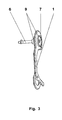
- FIG. 3 shows the one-piece component with sealing lids arranged on both sides, which are formed by the sealing edges 9.
- the outer side part 1 is firmly connected via the connecting part 7 with the supporting member 6.
- the connecting part 7 encloses on the one hand the non-round or knurled end piece of the supporting component 6 and on the other it engages in the openings and encloses on both sides of the outer side part 1 in the region of the supporting In this case, the connecting part 7 on both sides beyond the plate-shaped outer side part 1 and thus increases the axial overlap on the supporting member 6.
- This arranged on both sides, stiffening projection of the connecting part 7 forms the sealing edges 9, which requires the sealing of the chain guide receptacle and the tension roller bearing become.
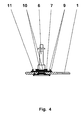
- FIG. 4 shows a sectional view of the FIG. 3 with the plate-shaped outer side part 1 made of aluminum or carbon fiber material, the supporting member 6 made of metal or fiber composite material and the connecting part 7 made of thermoplastic material.
- the connecting part 7 is produced by injection molding, after positioning insert and alignment of the other two components to each other in an injection molding tool.
- the connecting part 7 surrounds the equipped with two knurls 10 end of the supporting member 6, while the connecting part 7 protrudes in the region of the supporting member 6 substantially beyond the narrow, plate-shaped outer side part 1 addition. This projection thus extends the load-bearing connection length between the supporting member 6 and the connecting part 7.
- the distance between the supporting member 6 and the outer side part 1 is correspondingly large, so that the side part 1 is not applied to the supporting member 6 and a sufficient material thickness on the thermoplastic Can form connecting part 7 between the two adjacent components.
- the thickness of the plate-shaped outer side part 1 is very small, so that only a small radial contact surface between the connecting part 7 and the side part 1 results.
- This mounting problem is solved by recesses 11 and apertures, which are arranged at a distance from the large aperture, which receives the supporting member 6, on the outer side part 1.
- the recesses 11 and openings in the outer side part 1 allow the lateral engagement of the connecting part 7 and provide a positive connection between the side part 1 and the connecting part 7.
- sealing edges 9 are still arranged on the connecting part 7, whereby the connecting part. 7 can act as a side sealing lid.
- the sealing cover on the side of the supporting member 6 protects the chain guide receptacle against contamination, while the sealing cover on the other side seals the guide roller bearing laterally.
Landscapes
- Engineering & Computer Science (AREA)
- Chemical & Material Sciences (AREA)
- Combustion & Propulsion (AREA)
- Transportation (AREA)
- Mechanical Engineering (AREA)
- Devices For Conveying Motion By Means Of Endless Flexible Members (AREA)
- Injection Moulding Of Plastics Or The Like (AREA)
- Vehicle Body Suspensions (AREA)
- Body Structure For Vehicles (AREA)
Applications Claiming Priority (1)
| Application Number | Priority Date | Filing Date | Title |
|---|---|---|---|
| DE200610060221 DE102006060221A1 (de) | 2006-12-20 | 2006-12-20 | Kettenwerferbaugruppe |
Publications (3)
| Publication Number | Publication Date |
|---|---|
| EP1935775A2 true EP1935775A2 (fr) | 2008-06-25 |
| EP1935775A3 EP1935775A3 (fr) | 2009-03-25 |
| EP1935775B1 EP1935775B1 (fr) | 2009-11-18 |
Family
ID=38959620
Family Applications (1)
| Application Number | Title | Priority Date | Filing Date |
|---|---|---|---|
| EP20070023814 Ceased EP1935775B1 (fr) | 2006-12-20 | 2007-12-08 | Guide de chaîne pour dérailleur de bicyclette |
Country Status (5)
| Country | Link |
|---|---|
| US (1) | US9132884B2 (fr) |
| EP (1) | EP1935775B1 (fr) |
| CN (1) | CN101219701B (fr) |
| DE (2) | DE102006060221A1 (fr) |
| TW (1) | TWI372704B (fr) |
Families Citing this family (6)
| Publication number | Priority date | Publication date | Assignee | Title |
|---|---|---|---|---|
| US20080153640A1 (en) * | 2006-12-26 | 2008-06-26 | Shimano Inc. | Bicycle rear derailleur |
| US10207772B2 (en) | 2011-01-28 | 2019-02-19 | Paha Designs, Llc | Gear transmission and derailleur system |
| US9327792B2 (en) | 2011-01-28 | 2016-05-03 | Paha Designs, Llc | Gear transmission and derailleur system |
| US9033833B2 (en) | 2011-01-28 | 2015-05-19 | Paha Designs, Llc | Gear transmission and derailleur system |
| DE102018222834A1 (de) * | 2018-12-21 | 2020-06-25 | Sram Deutschland Gmbh | Halterungselement und Fahrrad mit einem Halterungselement |
| US11884364B2 (en) * | 2021-11-10 | 2024-01-30 | The Cycle Group | Rear derailleur with one-piece chain cage |
Family Cites Families (47)
| Publication number | Priority date | Publication date | Assignee | Title |
|---|---|---|---|---|
| US3125778A (en) * | 1964-03-24 | schutte | ||
| AT29994B (de) | 1906-03-31 | 1907-09-25 | Paul Schleich | Rost für Feuerungen. |
| US2756354A (en) * | 1954-03-16 | 1956-07-24 | Outil Electr Silex S A | Armatures of electric motors |
| US3085821A (en) * | 1960-04-22 | 1963-04-16 | Gen Motors Corp | Windshield wiper arm attachment |
| FR1319997A (fr) * | 1962-04-20 | 1963-03-01 | Changement de vitesse par déraillement de chaîne, en éléments combinés en matière plastique et en métal pour cycles, tandems, vélomoteurs, motocyclettes ou véhicules similaires | |
| GB1069591A (en) * | 1964-01-09 | 1967-05-17 | Willi Thielmann | Improvements in or relating to shaft couplings |
| US3364762A (en) * | 1964-10-07 | 1968-01-23 | Maeda Tetsuo | Change speed gear control device for bicycles or the like |
| US3313177A (en) * | 1965-06-16 | 1967-04-11 | Hamlin Metal Products Corp | Foot pedal |
| FR2114148A5 (fr) * | 1970-11-16 | 1972-06-30 | Crouzet Sa | |
| FR2213864B1 (fr) * | 1973-01-15 | 1977-07-29 | Huret Roger | |
| FR2259007B1 (fr) * | 1974-01-30 | 1977-06-10 | Huret Roger | |
| US4058020A (en) * | 1974-01-30 | 1977-11-15 | Roger Huret | Device for guiding the chain of derailleur bicycle gear changers |
| US4002080A (en) * | 1975-02-19 | 1977-01-11 | Roger Huret | Derailleur gear for a bicycle |
| US4198874A (en) * | 1977-05-20 | 1980-04-22 | Shimano Industrial Company Limited | Derailleur for bicycles and similar vehicles |
| JPS5457736A (en) * | 1977-10-14 | 1979-05-09 | Maeda Ind | Sheath transmission for bicycle |
| FR2454954A1 (fr) * | 1979-04-23 | 1980-11-21 | Huret Roger | Derailleur pour cycle |
| JPS593022Y2 (ja) * | 1979-05-04 | 1984-01-27 | 株式会社シマノ | 自転車用デイレ−ラ− |
| FR2466388A1 (fr) * | 1979-10-05 | 1981-04-10 | Huret Roger | Derailleur pour cycle |
| JPS6015516B2 (ja) * | 1979-12-19 | 1985-04-19 | 株式会社シマノ | 自転車用デイレ−ラ− |
| US4433963A (en) * | 1979-12-29 | 1984-02-28 | Shimano Industrial Company Limited | Chain guide for a derailleur for a bicycle |
| JPS57101123A (en) * | 1980-12-15 | 1982-06-23 | V I V Eng Kk | Bearing housing manufacturing method |
| DE3145002C2 (de) * | 1981-11-12 | 1984-03-22 | Detmar 4980 Bünde Grünfeld | Verbindung von aus Rohren hergestellten Teilen von Fahrradrahmen bzw. -gabeln sowie Verfahren zur Herstellung derselben |
| FR2560816B1 (fr) * | 1984-03-12 | 1986-10-03 | Simplex Ets | Procede de fabrication et de montage d'organes tournants entre des flasques et les produits obtenus, utilisables notamment pour tendre et enrouler la chaine dans les changements de vitesse pour cycles et vehicules similaires |
| FR2579949A2 (en) * | 1984-04-24 | 1986-10-10 | Simplex Ets | Mounting device especially for the articulation of the gear-change chain-guide tensioning arm for bicycles and similar vehicles |
| JPS61205587A (ja) * | 1985-03-08 | 1986-09-11 | 株式会社シマノ | 自転車用操作レバ− |
| US4826346A (en) * | 1985-04-11 | 1989-05-02 | Mitsubishi Jukogyo Kabushiki Kaisha | Camshaft preferably for an internal combustion engine |
| JPH0238879Y2 (fr) * | 1985-07-16 | 1990-10-18 | ||
| JPS62166191U (fr) * | 1986-04-12 | 1987-10-22 | ||
| JPS63184589A (ja) * | 1987-01-28 | 1988-07-30 | 株式会社シマノ | 自転車用デイレ−ラ− |
| US4832667A (en) * | 1987-08-06 | 1989-05-23 | Wren Nicholas D | Front chain wheel chain guide |
| IT215965Z2 (it) * | 1988-09-30 | 1991-03-20 | Perotti Ofmega Snc | Deragliatore di catena per cambi di velocita' di biciclette. |
| FR2663094A1 (fr) * | 1990-06-07 | 1991-12-13 | Simplex Sa | Ensemble-support pour le montage d'organes tournants. |
| DE4031983A1 (de) * | 1990-10-09 | 1992-04-16 | Fichtel & Sachs Ag | Umwerfer fuer eine fahrrad-kettenschaltung |
| FR2687977B1 (fr) * | 1992-02-27 | 1994-04-22 | Bg Innovation | Dispositifs permettant les changements de vitesses sur bicyclettes. |
| US5456637A (en) * | 1994-10-07 | 1995-10-10 | Chang; Shu-Gen | Chain shifting device for bicycle |
| JPH11500377A (ja) * | 1994-11-16 | 1999-01-12 | ビルド エス.エー. | 調節自在な自転車のフレーム |
| US6123353A (en) * | 1997-02-19 | 2000-09-26 | Techmatics, Inc. | Method of joining and reinforcing molded plastic bicycle frames |
| US5836844A (en) * | 1997-05-15 | 1998-11-17 | Shimano Inc. | Rear derailleur for a bicycle |
| DE19816406A1 (de) * | 1998-04-11 | 1999-10-14 | Skf Gmbh | Flanschlager |
| IT1307681B1 (it) * | 1999-04-13 | 2001-11-14 | Campagnolo Srl | Deragliatore posteriore di bicicletta. |
| IT1320646B1 (it) * | 2000-09-15 | 2003-12-10 | Campagnolo Srl | Forcella di deragliatore anteriore di bicicletta, e deragliatorecomprendente tale forcella. |
| US6528922B2 (en) * | 2000-10-06 | 2003-03-04 | New Bright Industrial Co., Ltd. | Motor housing having simplified cover plate and brush base |
| IT1321087B1 (it) * | 2000-11-24 | 2003-12-30 | Campagnolo Srl | Deragliatore posteriore per cambi di velocita' per biciclette. |
| ITTO20001124A1 (it) * | 2000-12-01 | 2002-06-01 | Campagnolo Srl | Gruppo bilanciere per il deragliatore posteriore di una bicicletta. |
| US6761187B1 (en) * | 2003-04-03 | 2004-07-13 | Bayer Polymers Llc | Tubular assembly having an internal plug |
| DE102004027031A1 (de) * | 2004-06-02 | 2006-01-05 | Schmittergroup Ag | Montagehilfe für einen zu verschraubenden Gegenstand |
| EP1602572A1 (fr) * | 2004-06-04 | 2005-12-07 | Campagnolo S.R.L. | Guide de chaíne pour dérailleur avant de bicyclette |
-
2006
- 2006-12-20 DE DE200610060221 patent/DE102006060221A1/de not_active Withdrawn
-
2007
- 2007-12-08 DE DE200750002025 patent/DE502007002025D1/de active Active
- 2007-12-08 EP EP20070023814 patent/EP1935775B1/fr not_active Ceased
- 2007-12-17 TW TW096148188A patent/TWI372704B/zh not_active IP Right Cessation
- 2007-12-20 CN CN200710160014XA patent/CN101219701B/zh not_active Expired - Fee Related
- 2007-12-20 US US11/961,915 patent/US9132884B2/en active Active
Also Published As
| Publication number | Publication date |
|---|---|
| EP1935775B1 (fr) | 2009-11-18 |
| CN101219701A (zh) | 2008-07-16 |
| TW200902380A (en) | 2009-01-16 |
| CN101219701B (zh) | 2012-08-08 |
| DE502007002025D1 (de) | 2009-12-31 |
| DE102006060221A1 (de) | 2008-06-26 |
| US20080153641A1 (en) | 2008-06-26 |
| US9132884B2 (en) | 2015-09-15 |
| EP1935775A3 (fr) | 2009-03-25 |
| TWI372704B (en) | 2012-09-21 |
Similar Documents
| Publication | Publication Date | Title |
|---|---|---|
| EP1935775B1 (fr) | Guide de chaîne pour dérailleur de bicyclette | |
| DE112007000157T5 (de) | Zahnstangendruckstückbaugruppe zur Verwendung in einer Zahnstangenlenkungsvorrichtung | |
| DE69413458T2 (de) | Aufbau und Verfahren zum Zusammenfügen von Strangpressprofilen | |
| DE19962988A1 (de) | Fahrzeugtür und Montageverfahren für eine Fahrzeugtür | |
| EP3568257B1 (fr) | Ensemble de pièces comprenant au moins deux pièces et procédé de production d'un ensemble de pièces assemblées par complémentarité de forme et/ou à force | |
| EP2175167B1 (fr) | Entraînement linéaire et boîtier pour un entraînement linéaire ainsi que procédé de fabrication d'un entraînement linéaire | |
| DE2733772A1 (de) | Kreuzgelenk, insbesondere fuer lenkvorrichtungen von kraftfahrzeugen | |
| DE19754248A1 (de) | Verbundbauteile mit mindestens einem Gußteil aus einem Leichtmetallwerkstoff | |
| DE102017200564A1 (de) | Bauteil mit Fügehilfselement, Bauteilverbund von mindestens zwei Bauteilen und Verfahren zur Herstellung | |
| EP1037775A1 (fr) | Platine tubulaire pour systeme d'essuie-glace | |
| WO2014063838A1 (fr) | Élément structural, procédé de fabrication d'un élément structural et utilisation de l'élément structural comme dossier de siège | |
| EP1431494B1 (fr) | Entrainement pour l'ouvrant d'une porte ou d'une fenêtre | |
| EP4538068B1 (fr) | Bras de suspension pour véhicule automobile | |
| EP3054182B1 (fr) | Procédé de fabrication d'une liaison bout à bout entre un boîtier articulé et un composant de liaison et élément de construction fabriqué selon ledit procédé | |
| DE19754170A1 (de) | Leichtmetallbauteil | |
| CH696489A5 (de) | Elektrisches Handwerkzeug mit einer mehrteiligen Lagerbrücke. | |
| DE202010000258U1 (de) | Kugelgelenk, insbesondere für ein Fahrwerk eines Kraftfahrzeuges | |
| DE102008004324A1 (de) | Scheibenwischeranlage an einem Fahrzeug | |
| DE3508380C2 (fr) | ||
| EP1963717A1 (fr) | Carter de differentiel et procede de realisation | |
| DE102007036442A1 (de) | Verfahren zur Herstellung einer Gleitlagerstelle bei einem Gussbauteil, das vorzugsweise als Spannhebel eines Riemenspanners ausgebildet ist sowie Gussbauteil selbst | |
| DE102016211673A1 (de) | Verfahren zur Herstellung einer Schalteinheit | |
| EP1817186B1 (fr) | Procede pour fixer des anneaux de fixation sur des stabilisateurs pour vehicules automobiles | |
| WO2003004322A1 (fr) | Piece de fixation moulee pour bras d'essuie-glace | |
| DE102007036103A1 (de) | Getriebebauteil sowie Verfahren zur Herstellung des Getriebebauteils |
Legal Events
| Date | Code | Title | Description |
|---|---|---|---|
| PUAI | Public reference made under article 153(3) epc to a published international application that has entered the european phase |
Free format text: ORIGINAL CODE: 0009012 |
|
| AK | Designated contracting states |
Kind code of ref document: A2 Designated state(s): AT BE BG CH CY CZ DE DK EE ES FI FR GB GR HU IE IS IT LI LT LU LV MC MT NL PL PT RO SE SI SK TR |
|
| AX | Request for extension of the european patent |
Extension state: AL BA HR MK RS |
|
| PUAL | Search report despatched |
Free format text: ORIGINAL CODE: 0009013 |
|
| 111Z | Information provided on other rights and legal means of execution |
Free format text: AT BE BG CH CY CZ DE DK EE ES FI FR GB GR HU IE IS IT LT LU LV MC MT NL PL PT RO SE SI SK TR Effective date: 20090106 |
|
| AK | Designated contracting states |
Kind code of ref document: A3 Designated state(s): AT BE BG CH CY CZ DE DK EE ES FI FR GB GR HU IE IS IT LI LT LU LV MC MT NL PL PT RO SE SI SK TR |
|
| AX | Request for extension of the european patent |
Extension state: AL BA HR MK RS |
|
| 17P | Request for examination filed |
Effective date: 20090411 |
|
| GRAP | Despatch of communication of intention to grant a patent |
Free format text: ORIGINAL CODE: EPIDOSNIGR1 |
|
| GRAS | Grant fee paid |
Free format text: ORIGINAL CODE: EPIDOSNIGR3 |
|
| GRAA | (expected) grant |
Free format text: ORIGINAL CODE: 0009210 |
|
| AK | Designated contracting states |
Kind code of ref document: B1 Designated state(s): DE FR NL |
|
| AKX | Designation fees paid |
Designated state(s): DE FR NL |
|
| REF | Corresponds to: |
Ref document number: 502007002025 Country of ref document: DE Date of ref document: 20091231 Kind code of ref document: P |
|
| PLBE | No opposition filed within time limit |
Free format text: ORIGINAL CODE: 0009261 |
|
| STAA | Information on the status of an ep patent application or granted ep patent |
Free format text: STATUS: NO OPPOSITION FILED WITHIN TIME LIMIT |
|
| 26N | No opposition filed |
Effective date: 20100819 |
|
| REG | Reference to a national code |
Ref country code: FR Ref legal event code: PLFP Year of fee payment: 9 |
|
| REG | Reference to a national code |
Ref country code: FR Ref legal event code: PLFP Year of fee payment: 10 |
|
| REG | Reference to a national code |
Ref country code: FR Ref legal event code: PLFP Year of fee payment: 11 |
|
| P01 | Opt-out of the competence of the unified patent court (upc) registered |
Effective date: 20230523 |
|
| PGFP | Annual fee paid to national office [announced via postgrant information from national office to epo] |
Ref country code: NL Payment date: 20231220 Year of fee payment: 17 Ref country code: FR Payment date: 20231221 Year of fee payment: 17 |
|
| PGFP | Annual fee paid to national office [announced via postgrant information from national office to epo] |
Ref country code: DE Payment date: 20231221 Year of fee payment: 17 |
|
| REG | Reference to a national code |
Ref country code: DE Ref legal event code: R119 Ref document number: 502007002025 Country of ref document: DE |
|
| REG | Reference to a national code |
Ref country code: NL Ref legal event code: MM Effective date: 20250101 |
|
| PG25 | Lapsed in a contracting state [announced via postgrant information from national office to epo] |
Ref country code: NL Free format text: LAPSE BECAUSE OF NON-PAYMENT OF DUE FEES Effective date: 20250101 |
|
| PG25 | Lapsed in a contracting state [announced via postgrant information from national office to epo] |
Ref country code: DE Free format text: LAPSE BECAUSE OF NON-PAYMENT OF DUE FEES Effective date: 20250701 |
|
| PG25 | Lapsed in a contracting state [announced via postgrant information from national office to epo] |
Ref country code: FR Free format text: LAPSE BECAUSE OF NON-PAYMENT OF DUE FEES Effective date: 20241231 |