EP1936061A2 - Markise mit Volant - Google Patents
Markise mit Volant Download PDFInfo
- Publication number
- EP1936061A2 EP1936061A2 EP07020671A EP07020671A EP1936061A2 EP 1936061 A2 EP1936061 A2 EP 1936061A2 EP 07020671 A EP07020671 A EP 07020671A EP 07020671 A EP07020671 A EP 07020671A EP 1936061 A2 EP1936061 A2 EP 1936061A2
- Authority
- EP
- European Patent Office
- Prior art keywords
- valance
- shaft
- support surface
- sunshade according
- support
- Prior art date
- Legal status (The legal status is an assumption and is not a legal conclusion. Google has not performed a legal analysis and makes no representation as to the accuracy of the status listed.)
- Granted
Links
Images
Classifications
-
- E—FIXED CONSTRUCTIONS
- E04—BUILDING
- E04F—FINISHING WORK ON BUILDINGS, e.g. STAIRS, FLOORS
- E04F10/00—Sunshades, e.g. Florentine blinds or jalousies; Outside screens; Awnings or baldachins
- E04F10/02—Sunshades, e.g. Florentine blinds or jalousies; Outside screens; Awnings or baldachins of flexible canopy materials, e.g. canvas ; Baldachins
- E04F10/06—Sunshades, e.g. Florentine blinds or jalousies; Outside screens; Awnings or baldachins of flexible canopy materials, e.g. canvas ; Baldachins comprising a roller-blind with means for holding the end away from a building
- E04F10/0692—Front bars
- E04F10/0696—Front bars with means to attach an auxiliary screen
-
- E—FIXED CONSTRUCTIONS
- E04—BUILDING
- E04F—FINISHING WORK ON BUILDINGS, e.g. STAIRS, FLOORS
- E04F10/00—Sunshades, e.g. Florentine blinds or jalousies; Outside screens; Awnings or baldachins
- E04F10/02—Sunshades, e.g. Florentine blinds or jalousies; Outside screens; Awnings or baldachins of flexible canopy materials, e.g. canvas ; Baldachins
- E04F10/06—Sunshades, e.g. Florentine blinds or jalousies; Outside screens; Awnings or baldachins of flexible canopy materials, e.g. canvas ; Baldachins comprising a roller-blind with means for holding the end away from a building
- E04F10/0666—Accessories
- E04F10/0677—Accessories acting as centre bearing
Definitions
- the invention relates to an extendable sunshade, in particular awning or articulated arm awning, with an extension profile, on which a detachable from a rotatably mounted cloth shaft cloth is attached, wherein the Ausfahrprofil an extendable valance is arranged and wherein the valance of a rotatably mounted volant shaft is unwound.
- Such an awning is known with an awning fabric, wherein the front edge of the awning fabric is attached to a skirt, with which the awning fabric is pulled off during clamping of a fabric shaft on which it is wound into a cloth awning and wherein on the skirt or the Ausfahrprofil a rotatably mounted volant shaft is arranged, from which a valance is vertically unwound.
- the object of the invention is therefore to provide an extendable sunshade, in which an extendable valance is arranged on the extension profile and wherein the valance of a rotatably mounted volant shaft is unwound, such that a Deflection of the valance shaft is avoided in order to avoid the aforementioned disadvantages and in particular prevents wrinkling in the valance,
- the awning is designed with valance of the shape that the Volantwelle in the unwinding back and forth is moved, as this ensures that the reel of the ruffle is always supported on the support or support surface, as due to the pros - And scatterbewegles the volant shaft in the extension direction of the wound bales always rests against the support surface, even if the diameter of the bale as a result of the settlement of the valance, ie by the extension of the valance, reduced in size. As a result, deflection of the valance shaft is counteracted effectively and in a structurally simple manner.
- the valance may be formed by a cloth or fabric or a transparent curtain or the like.
- the valance may extend to the ground, in particular to provide a visual and / or sun protection.
- the support on a support surface which extends over almost the entire length of the valance shaft and at least a large part of the extension direction facing peripheral surface of the wound on the Volantwelle Volanttuchballens supported.
- This embodiment has the advantage that the main load of the volant shaft during winding and unwinding is absorbed primarily by the two bearings, at the ends of the valance shaft, with only very small on the incoming or expiring valance Frictional forces are exerted, but that the winding bale of the valance is supported on almost its entire width on its underside by the support surface over a large area, when the bale completely fills and the Volantwelle bends down under the weight of the fully wound bale wrap.
- the winding shaft bearings slide down so that the winding bale always rests against the support surface and is supported by this.
- the winding shaft preferably has at its ends substantially vertically displaceable sliding bearings which are independently displaceable against adjustable stops forward and backward.
- the valance shaft can be mounted at their ends in sliding blocks, which slide in slide guides of bearing supports.
- each sliding block can be determined at any point of its link guide and it is possible to adjust by sliding stops in the slide guide the sliding path of the sliding blocks and limit.
- the valance shaft by means of an electric motor, in particular by means of an operable by a remote control electric motor, can be driven.
- the support surface preferably has at least one friction-reducing insert and / or support. Because the support surface has at least one friction-reducing insert and / or support, the static friction between the winding bale of the valance and the support surface is reduced, in particular adhesion of the winding bale to the support surface is prevented. It is particularly advantageous that for a winding up and unwinding of the valance due to the reduced stiction between Volantwickelballen and support surface only lower forces, or torques on the winding shaft are required and at the same time a uniform winding of the Volanttuches on the Volantwelle is made possible to a bale ,
- the inserts and / or supports are formed by brushing and / or felt and / or batt.
- the inserts and / or supports are strip-shaped, in particular in the form of the axis of the winding shaft parallel strips are formed.
- the inserts and / or pads are positively in a corresponding recesses of the support surface, in particular in dovetail grooves or T-shaped grooves.
- the correspondingly shaped deposits during assembly from the side into the corresponding grooves of the support surface, which is particularly preferably parallel to the winding shaft in the support surface are arranged.
- the inserts and / or supports can be non-positively, in particular by clamping in corresponding recesses of the support surface, in particular eino in grooves.
- the inserts and / or pads may be adhered to the support surface.
- the support surface has a concave shape, in particular a part-cylindrical shape.
- the curvature of the cylindrical surface is in this case preferably adapted to the curvature of the outer circumference of the wound bale completely wound on the volant shaft.
- the support surface extends over almost the entire length of the Volantwelle, respectively, it corresponds in its extension of the length of the Volantwelle.
- the support surface has a directed to the unwinding of the flat shading and / or privacy protection guide edge for the Volanttuch on which the Volanttuch can slide along during winding and unwinding.
- the guide edge is convexly curved, so that the valance always rests on a large support surface and gently slide along it.
- the support surface is designed such that it supports the winding bale of the valance against the force of gravity. It is particularly advantageous if the support surface extends around the winding bale over an angle of 90 ° to 180 °, in particular at least 120 °. As a result, a large-scale support of the wrapping bale is possible.
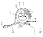
- a valance 410 is shown in a cross section.
- the valance 410 has a housing 411.
- the winding shaft 413 is rotatably supported with the winding bale 414 wound thereon.
- the valance 410 is attached to the front of the partially illustrated Ausfahrprofils 412 an articulated arm awning.
- the housing 411 of the valance 410 is designed such that this has an upper edge of the Ausfahrprofils 412 cross hook-shaped projection 415, so that the valance 410 and the housing 411 of the valance 410 mounted on the Ausfahrprofil 412 of the awning and by means not shown fastening screws in the lower part of the extension profile 412 is fixed.
- the front cloth end 416 of the coiled cloth bale 414 of the valance hangs down freely and is actuated, i. Rotation of the volant shaft 413 downwards extendable.
- the valance shaft 413 has at its end shaft journals, not shown, with which it is rotatably mounted in sliding blocks.
- the sliding blocks in turn are mounted in slide guides of bearing supports so that they can move independently back and forth in the direction of the arrows 424 and 425 in the direction of the support surface 451 in the extension of the valance, ie that the bale 414 regardless of its depending the extension of the Volumes changing diameter is always applied to the support surface 451 and the support surface 451 thus counteracts a deflection of the valance shaft 413 with the winding bale 414.
- the support surface 451 has a part-cylindrical surface, which is directed towards the tissue ball 414 and whose diameter corresponds approximately to the diameter of the tissue bale 414 in the fully wound state.
- the supporting device On the inside of the support surface 451, d. H. on the supporting surface in the direction of the winding bale 414, the supporting device has a plurality of friction-reducing inserts 454 which are inserted in grooves 453. Due to the arrangement of the friction-reducing deposits 454, the winding bale 414 is supported against the gravity directed in the direction of the arrow 425 and ensures a smooth sliding of the winding bale 414 on the support surface 451 and prevents bending of the volant shaft 413 ..
- the winding shaft 413 moves vertically downward in the lateral bearings accordingly, so that the winding bale 414 always on the support surface 451 is supported and supported by it.
Landscapes
- Engineering & Computer Science (AREA)
- Architecture (AREA)
- Civil Engineering (AREA)
- Structural Engineering (AREA)
- Building Awnings And Sunshades (AREA)
- Operating, Guiding And Securing Of Roll- Type Closing Members (AREA)
Abstract
Description
- Die Erfindung betrifft einen ausfahrbaren Sonnenschutz, insbesondere Markise oder Gelenkarmmarkise, mit einem Ausfahrprofil, an dem ein von einer drehbar gelagerten Tuchwelle abziehbares Tuch befestigt ist, wobei am Ausfahrprofil ein ausfahrbarer Volant angeordnet ist und wobei der Volant von einer drehbar gelagerten Volantwelle abwickelbar ist.
- Aus der
DE 103 07 226 ist eine derartige Markise mit einem Markisentuch bekannt, wobei der vordere Rand des Markisentuches an einer Randleiste befestigt ist, mit der das Markisentuch beim Aufspannen von einer Tuchwelle abgezogen wird, auf der es zu einem Markisentuchballen aufgewickelt ist und wobei an der Randleiste bzw. dem Ausfahrprofil eine drehbar gelagerte Volantwelle angeordnet ist, von der ein Volant senkrecht abwickelbar ist. - Hierbei hat sich gezeigt, dass die Volantwelle sich unter ihrem eigenen Gewicht sowie unter dem Gewicht des Wickelballens des Volants durchbiegen kann. Nachteilig ist dabei, dass dies zu Falten in dem Volant infolge der Durchbiegung der Volantwelle führen kann mit der Folge einer optischen Beeinträchtigung durch die Faltenbildung. Langfristig kann dies zu einer Beschädigung des Volanttuches führen.
- Aufgabe der Erfindung ist es daher, einen ausfahrbaren Sonnenschutz, bei dem am Ausfahrprofil ein ausfahrbarer Volant angeordnet ist und wobei der Volant von einer drehbar gelagerten Volantwelle abwickelbar ist, derart weiterzubilden, dass eine Durchbiegung der Volantwelle vermieden wird, um die vorgenannten Nachteile zu vermeiden und insbesondere eine Faltenbildung im Volant unterbleibt,
- Diese Aufgabe wird erfindungsgemäß dadurch gelöst, dass bei einem gattungsgemäßen Sonnenschutz, bei dem am Ausfahrprofil ein ausfahrbarer Volant angeordnet ist und wobei der Volant von einer drehbar gelagerten Volantwelle abwickelbar ist, die Volantwelle wenigstens in ihrem mittleren Bereich durch eine Stützung oder Stützfläche abgestützt ist und dass die Volantwelle in Ausfahrrichtung des Volants vor- und zurückbewegbar ist.
- Besonders vorteilhaft ist dabei, dass die Markise mit Volant der Gestalt ausgebildet ist, dass die Volantwelle in Abwickelrichtung vor- und zurückbewegbar ist, da dadurch gewährleistet ist, dass sich der Wickelballen des Volants stets an der Stützung oder Stützfläche abstützt, da auf Grund der Vor- und Zurückbewegbarkeit der Volantwelle in Ausfahrrichtung der Wickelballen stets an der Stützfläche anliegt, auch wenn sich der Durchmesser des Wickelballens infolge der Abwicklung des Volants, d.h. durch das Ausfahren des Volants, verkleinert. Hierdurch wird einer Durchbiegung der Volantwelle effektiv und auf konstruktiv einfache Weise entgegengewirkt.
- Der Volant kann gebildet sein durch ein Tuch oder Stoff oder einen transparenten Behang oder dgl. Insbesondere kann der Volant bis zum Boden reichen, um insbesondere einen Sicht- und/oder Sonnenschutz zu bieten.
- Weitere vorteilhafte Ausgestaltungen sind in den Unteransprüchen gegeben.
- Vorzugsweise weist die Stützung eine Stützfläche auf, welche sich über nahezu die ganze Länge der Volantwelle erstreckt und mindestens einen großen Teil der der Ausfahrrichtung zugewandeten Umfangsfläche des auf der Volantwelle aufgewickelten Volanttuchballens abstützt.
- Diese Ausgestaltung hat den Vorteil, dass die Hauptlast der Volantwelle beim Auf- und Abwickeln in erster Linie von den beiden Lagern, an den Enden der Volantwelle aufgenommen wird, wobei auf den ein- oder auslaufende Volant nur sehr geringe Reibungskräfte ausgeübt werden, dass aber der Wickelballen des Volants auf nahezu seiner ganzen Breite auf seiner Unterseite von der Stützfläche großflächig abgestützt wird, wenn der Wickelballen sich vollständig füllt und die Volantwelle unter dem Gewicht des vollständig aufgewickelten Wickelballens sich nach unten durchbiegt. Beim Abrollen des Volants gleiten die Wickelwellenlager nach unten, so dass der Wickelballen stets an der Stützfläche anliegt und von dieser abgestützt wird.
- Die Wickelwelle hat an ihren Enden vorzugsweise im wesentlichen vertikal verschiebbare Schiebelager, die unabhängig voneinander gegen verstellbare Anschläge vor- und zurückverschiebbar sind.
- Die Volantwelle kann an ihren Enden in Gleitsteinen gelagert sein, die in Kulissenführungen von Lagerträgern gleiten. Hierbei kann jeder Gleitstein an einer beliebigen Stelle seiner Kulissenführung feststellbar sein und es ist möglich, durch verstellbare Anschläge in der Kulissenführung den Gleitweg der Gleitsteine einzustellen und zu begrenzen.
- Vorzugsweise ist die Volantwelle mittels eines Elektromotors, insbesondere mittels eines durch eine Fernbedienung betätigbaren Elektromotors, antreibbar.
- Bevorzugt weist die Stützfläche zumindest eine reibungsmindernde Einlage und/oder Auflage auf. Dadurch, dass die Stützfläche zumindest eine reibungsmindernden Einlage und/oder Auflage aufweist, wird die Haftreibung zwischen dem Wickelballen des Volants und der Stützfläche gemindert, insbesondere wird ein Anhaften des Wickelballens an der Stützfläche verhindert. Besonders vorteilhaft ist dabei, dass für ein auf- und abwickeln des Volants in Folge der reduzierten Haftreibung zwischen Volantwickelballen und Stützfläche nur geringere Kräfte, bzw. Drehmomente an der Wickelwelle erforderlich sind und gleichzeitig ein gleichmäßiges Aufwickeln des Volanttuches auf der Volantwelle zu einem Wickelballen ermöglicht wird.
- Vorteilhaft ist es, wenn die Einlagen und/oder Auflagen durch Bürsten und/oder Filz und/oder Faserflor gebildet sind. Insbesondere ist vorteilhaft, wenn die Einlagen und/oder Auflagen streifenförmig, insbesondere in Form zur Achse der Wickelwelle paralleler Streifen ausgebildet sind. Alternativ ist es jedoch auch möglich, nicht lediglich einzelne Streifen, sondern eine großflächige reibungsmindernde Einlage und/oder Auflage in oder auf der Stützfläche vorzusehen, insbesondere in Form eines die gesamte Stützfläche bedeckenden Filzbelages oder dergleichen.
- Vorzugsweise liegen die Einlagen und/oder Auflagen formschlüssig in entsprechenden Ausnehmungen der Stützfläche ein, insbesondere in Schwalbenschwanznuten oder T-förmigen Nuten. Bei derartig gestalteten Nuten, in denen die Einlagen und/oder Auflagen einliegen, ist es in vorteilhafter Weise möglich, die entsprechend gestalteten Einlagen bei der Montage von der Seite her in die entsprechenden Nuten der Stützfläche einzuschieben, die insbesondere bevorzugt parallel zur Wickelwelle in der Stützfläche angeordnet sind.
- In einer weiteren bevorzugten Weise können die Einlagen und/oder Auflagen kraftschlüssig, insbesondere durch Klemmung in entsprechenden Ausnehmungen der Stützfläche, insbesondere in Nuten einliegen.
- Alternativ oder kumulativ können die Einlagen und/oder Auflagen auf die Stützfläche aufgeklebt sein.
- Bevorzugt weist die Stützfläche eine konkave Form, insbesondere eine teilzylindrische Form auf. Die Krümmung der Zylinderfläche wird hierbei vorzugsweise der Krümmung des Außenumfangs des vollständig auf der Volantwelle aufgewickelten Wickelballens angepasst.
- Vorzugsweise erstreckt sich die Stützfläche über nahezu die ganze Länge der Volantwelle, respektive sie entspricht in ihrer Erstreckung der Länge der Volantwelle.
- Vorteilhaft ist es, wenn die Stützfläche einen zur Abwickelrichtung des flächigen Beschattungs- und/oder Sichtschutzelementes gerichteten Führungsrand für das Volanttuch aufweist, auf dem das Volanttuch beim Auf- und Abwickeln entlanggleiten kann. Vorzugsweise ist der Führungsrand konvex gekrümmt, so dass der Volant immer auf einer großen Auflagefläche aufliegt und schonend daran entlanggleiten kann.
- Vorzugsweise ist die Stützfläche derart ausgebildet, dass sie den Wickelballen des Volants gegen die Schwerkraft abstützt. Insbesondere ist vorteilhaft, wenn sich die Stützfläche über einen Winkel von 90° bis 180°, insbesondere mindestens 120° um den Wickelballen herum erstreckt. Hierdurch ist eine großflächige Abstützung des Wickelballens möglich.
- Ein Ausführungsbeispiel eines erfindungsgemäßen Sonnenschutzes ist in den Zeichnungen dargestellt und werden im Folgenden näher erläutert. Es zeigt:
- Figur 1
- Einen Schnitt durch ein Ausfahrprofil einer Gelenkarmmarkise mit daran angeordnetem Volant.
- In
Fig. 1 ist ein Volant 410 in einem Querschnitt dargestellt. Der Volant 410 weist ein Gehäuse 411 auf. In dem Gehäuse 411 ist die Wickelwelle 413 mit dem darauf aufgewickelten Wickelballen 414 drehbar gelagert. - Der Volant 410 ist befestigt an der Vorderseite des teilweise dargestellten Ausfahrprofils 412 einer Gelenkarmmarkise. Hierzu ist das Gehäuse 411 des Volants 410 derart gestaltet, dass dies einen die obere Kante des Ausfahrprofils 412 übergreifenden hakenförmigen Vorsprung 415 aufweist, sodass der Volant 410 bzw. das Gehäuse 411 des Volants 410 an dem Ausfahrprofil 412 der Markise eingehängt und mittels nicht dargestellter Befestigungsschrauben im unteren Bereich an dem Ausfahrprofil 412 fixierbar ist.
- Das vordere Tuchende 416 des aufgewickelten Tuchballens 414 des Volants hängt frei nach unten und ist durch Betätigung, d.h. Drehung der Volantwelle 413 nach unten ausfahrbar.
- Die Volantwelle 413 hat an ihrem Ende nicht dargestellte Wellenzapfen, mit denen sie in Gleitsteinen drehbar gelagert ist. Die Gleitsteine wiederum sind in Kulissenführungen von Lagerträgern derart gelagert, dass sie sich unabhängig voneinander in Richtung der Pfeile 424 und 425 in Richtung auf die Stützfläche 451 in Ausfahrrichtung des Volants vor- und zurückbewegen können, d. h. dass der Wickelballen 414 unabhängig von seiner sich in Abhängigkeit der Ausfahrweite des Volants ändernden Durchmessers stets an der Stützfläche 451 anliegt und die Stützfläche 451 somit einer Durchbiegung der Volantwelle 413 mit dem Wickelballen 414 entgegenwirkt.
- Die Stützfläche 451 weist eine teilzylindrische Fläche auf, die zum Tuchballen 414 hin gerichtet ist und deren Durchmesser in etwa dem Durchmesser des Tuchballens 414 in voll aufgewickeltem Zustand entspricht. Auf der Innenseite der Stützfläche 451, d. h. auf der Stützfläche in Richtung des Wickelballens 414, weist die Stützvorrichtung mehrere, in Nuten 453 einliegende reibungsmindernde Einlagen 454 auf. Durch die Anordnung der reibungsmindernden Einlagen 454 wird der Wickelballen 414 gegen die in Richtung des Pfeiles 425 gerichtete Schwerkraft abgestützt und gewährleistet ein leichtgängiges Gleiten des Wickelballens 414 auf der Stützfläche 451 und verhindert eine Durchbiegung der Volantwelle 413..
- Sofern sich der Durchmesser des Wickelballens 414 ändert, dadurch dass der Volant senkrecht nach unten (in Richtung des Pfeiles 425) ausgefahren wird, verlagert sich die Wickelwelle 413 in den seitlichen Lagern dementsprechend senkrecht nach unten, so dass der Wickelballen 414 stets auf der Stützfläche 451 aufliegt und von dieser abgestützt wird.
- Durch die Anordnung einer Stützfläche 451 und die schwimmende Lagerung der Volantwelle 413 wird somit eine Durchbiegung der Volantwelle 413 mit dem Wickelballen 414 zuverlässig verhindert.
Claims (15)
- Ausfahrbarer Sonnenschutz, insbesondere Markise oder Gelenkarmmarkise, mit einem Ausfahrprofil, an dem ein von einer drehbar gelagerten Tuchwelle abziehbares Tuch befestigt ist, wobei am Ausfahrprofil ein ausfahrbarer Volant (410) angeordnet ist und wobei der Volant von einer drehbar gelagerten Volantwelle (413) abwickelbar ist, dadurch gekennzeichnet, dass die Volantwelle (413) wenigstens in ihrem mittleren Bereich durch eine Stützung oder Stützfläche (451) abgestützt ist und dass die Volantwelle (413) in Ausfahrrichtung des Volants vor- und zurückbewegbar ist.
- Sonnenschutz nach Anspruch 1, dadurch gekennzeichnet, dass die Stützung eine Stützfläche (451) aufweist, welche sich über nahezu die ganze Länge der Volantwelle (413) erstreckt und mindestens einen großen Teil der der Ausfahrrichtung zugewandeten Umfangsfläche des auf der Volantwelle (413) aufgewickelten Volanttuchballens (414) abstützt.
- Sonnenschutz nach Anspruch 1 oder 2, dadurch gekennzeichnet, dass die Stützfläche (414) einen zur Ausfahrrichtung gerichteten Führungsrand für den Volant aufweist.
- Sonnenschutz nach einem der vorherigen Ansprüche, dadurch gekennzeichnet, dass die Volantwelle (414) an ihren Enden in Gleitsteinen gelagert ist, die in Kulissenführungen von Lagerträgern gleiten.
- Sonnenschutz nach Anspruch 4, dadurch gekennzeichnet, dass jeder Gleitstein an einer beliebigen Stelle seiner Kulissenführung feststellbar ist.
- Sonnenschutz nach einem der vorherigen Ansprüche, dadurch gekennzeichnet, dass die Volantwelle (413) an ihren Enden Schiebelager aufweist, die unabhängig voneinander in Ausfahrrichtung vor- und zurückverschiebbar und/oder feststellbar sind, insbesondere dass der Verschiebeweg (s) der Schiebelager einstellbar ist.
- Sonnenschutz nach einem der vorherigen Ansprüche, dadurch gekennzeichnet, dass die Volantwelle (413) mittels eines Elektromotors, insbesondere mittels eines durch eine Fernbedienung betätigbaren Elektromotors, antreibbar ist.
- Sonnenschutz nach einem der vorherigen Ansprüche, dadurch gekennzeichnet, dass die Stützung eine Stützfläche (451) mit zumindest einer reibungsmindernden Einlage (454) und/oder Auflage aufweist
- Sonnenschutz nach einem Anspruch 8, dadurch gekennzeichnet, dass die Einlage(n) (454) und/oder Auflage(n) durch Bürsten und/oder Filz und/oder Faserflor gebildet ist (sind).
- Sonnenschutz nach Anspruch 8 oder 9, dadurch gekennzeichnet, dass die Einlage(n) (454) und/oder Auflage(n) streifenförmig, insbesondere in Form zur Achse der Wickelwelle (413) paralleler Streifen, ausgebildet ist (sind).
- Sonnenschutz nach einem der vorherigen Ansprüche, dadurch gekennzeichnet, dass reibungsmindernde Einlage(n) (454) und/oderAuflage(n) formschlüssig in entsprechenden Ausnehmungen der Stützfläche (451), insbesondere in Schwalbenschwanznuten oder T-förmigen Nuten (453), einliegen.
- Sonnenschutz nach einem der vorherigen Ansprüche, dadurch gekennzeichnet, dass reibungsmindernde Einlage(n) (454) und/oderAuflage(n) kraftschlüssig, insbesondere durch Klemmung, in entsprechenden Ausnehmungen der Stützfläche (451), insbesondere in Nuten, einliegen.
- Sonnenschutz nach einem der vorherigen Ansprüche, dadurch gekennzeichnet, dass reibungsmindernde Einlage(n) (454) und/oderAuflage(n) auf die Stützfläche (451) aufgeklebt sind.
- Sonnenschutz nach einem der vorherigen Ansprüche, dadurch gekennzeichnet, dass die Stützfläche (451) eine konkave Form, insbesondere eine teilzylindrische Form, aufweist.
- Sonnenschutz nach einem der vorherigen Ansprüche, dadurch gekennzeichnet, dass reibungsmindernde Einlage(n) (454) und/oderAuflage(n) in dem Bereich der Stützfläche (451) angeordnet sind, der den Wickelballen (414) der Volantwelle (413) gegen die Schwerkraft abstützt.
Applications Claiming Priority (1)
| Application Number | Priority Date | Filing Date | Title |
|---|---|---|---|
| DE200610059467 DE102006059467A1 (de) | 2006-12-14 | 2006-12-14 | Markise mit Volant |
Publications (3)
| Publication Number | Publication Date |
|---|---|
| EP1936061A2 true EP1936061A2 (de) | 2008-06-25 |
| EP1936061A3 EP1936061A3 (de) | 2013-08-28 |
| EP1936061B1 EP1936061B1 (de) | 2014-06-25 |
Family
ID=39203159
Family Applications (1)
| Application Number | Title | Priority Date | Filing Date |
|---|---|---|---|
| EP20070020671 Active EP1936061B1 (de) | 2006-12-14 | 2007-10-23 | Markise mit Volant |
Country Status (2)
| Country | Link |
|---|---|
| EP (1) | EP1936061B1 (de) |
| DE (1) | DE102006059467A1 (de) |
Cited By (7)
| Publication number | Priority date | Publication date | Assignee | Title |
|---|---|---|---|---|
| ITTO20090078A1 (it) * | 2009-02-06 | 2009-05-08 | Fandis S P A | Sistema di schermatura avvolgibile isostatico |
| BE1019025A3 (nl) * | 2009-08-31 | 2012-01-10 | Brustor Nv | Volant of voordoek van een luifel. |
| ITBO20120178A1 (it) * | 2012-04-04 | 2013-10-05 | Valla S R L | Congegno tenditela basculante per tende da sole. |
| EP2199484B1 (de) | 2008-12-22 | 2016-07-06 | Weinor GmbH & Co. KG | Steuerung elektrischer Verbraucher per Funkfernbedienung in einer Beschattungseinrichtung |
| EP3741924A1 (de) * | 2019-05-24 | 2020-11-25 | weinor GmbH & Co. KG | Wintergartenmarkise mit volant |
| EP4293189A1 (de) | 2022-06-14 | 2023-12-20 | markilux GmbH + Co. KG | Senkrechtmarkise, insbesondere fenster- oder volantmarkise |
| DE102023111498A1 (de) * | 2023-05-03 | 2024-11-07 | Peggy Peg Innovative Systems GmbH | Rollosystem |
Citations (3)
| Publication number | Priority date | Publication date | Assignee | Title |
|---|---|---|---|---|
| DE29920856U1 (de) | 1999-02-25 | 2000-03-16 | Roedelbronn Gmbh | Tuchwellenlager |
| DE10001757A1 (de) | 2000-01-18 | 2001-08-02 | Schmitz Werke | Vertikalmarkise |
| DE10307226A1 (de) | 2003-02-20 | 2004-09-02 | Weinor Dieter Weiermann Gmbh & Co. | Ausfahrbarer Sonnenschutz |
Family Cites Families (4)
| Publication number | Priority date | Publication date | Assignee | Title |
|---|---|---|---|---|
| DE7510762U (de) * | 1975-04-05 | 1977-06-23 | Clauss-Markisen, 7311 Ochsenwang | Markise |
| DE8001376U1 (de) * | 1980-01-19 | 1985-04-18 | Lohausen, Viktor, 7032 Sindelfingen | Markise |
| DE29624389U1 (de) * | 1995-06-01 | 2002-12-05 | "Weinor" Dieter Weiermann GmbH & Co, 50829 Köln | Markise |
| DE19949215A1 (de) * | 1999-10-13 | 2001-04-19 | Schmitz Werke | Markise |
-
2006
- 2006-12-14 DE DE200610059467 patent/DE102006059467A1/de not_active Ceased
-
2007
- 2007-10-23 EP EP20070020671 patent/EP1936061B1/de active Active
Patent Citations (3)
| Publication number | Priority date | Publication date | Assignee | Title |
|---|---|---|---|---|
| DE29920856U1 (de) | 1999-02-25 | 2000-03-16 | Roedelbronn Gmbh | Tuchwellenlager |
| DE10001757A1 (de) | 2000-01-18 | 2001-08-02 | Schmitz Werke | Vertikalmarkise |
| DE10307226A1 (de) | 2003-02-20 | 2004-09-02 | Weinor Dieter Weiermann Gmbh & Co. | Ausfahrbarer Sonnenschutz |
Cited By (7)
| Publication number | Priority date | Publication date | Assignee | Title |
|---|---|---|---|---|
| EP2199484B1 (de) | 2008-12-22 | 2016-07-06 | Weinor GmbH & Co. KG | Steuerung elektrischer Verbraucher per Funkfernbedienung in einer Beschattungseinrichtung |
| ITTO20090078A1 (it) * | 2009-02-06 | 2009-05-08 | Fandis S P A | Sistema di schermatura avvolgibile isostatico |
| BE1019025A3 (nl) * | 2009-08-31 | 2012-01-10 | Brustor Nv | Volant of voordoek van een luifel. |
| ITBO20120178A1 (it) * | 2012-04-04 | 2013-10-05 | Valla S R L | Congegno tenditela basculante per tende da sole. |
| EP3741924A1 (de) * | 2019-05-24 | 2020-11-25 | weinor GmbH & Co. KG | Wintergartenmarkise mit volant |
| EP4293189A1 (de) | 2022-06-14 | 2023-12-20 | markilux GmbH + Co. KG | Senkrechtmarkise, insbesondere fenster- oder volantmarkise |
| DE102023111498A1 (de) * | 2023-05-03 | 2024-11-07 | Peggy Peg Innovative Systems GmbH | Rollosystem |
Also Published As
| Publication number | Publication date |
|---|---|
| EP1936061B1 (de) | 2014-06-25 |
| DE102006059467A1 (de) | 2008-06-19 |
| EP1936061A3 (de) | 2013-08-28 |
Similar Documents
| Publication | Publication Date | Title |
|---|---|---|
| EP1936061B1 (de) | Markise mit Volant | |
| EP0745742B1 (de) | Markise | |
| EP2452034A2 (de) | Wickelvorrichtung zum bedecken von wandöffnungen oder fenstern | |
| EP3260623B1 (de) | Roll-markise | |
| EP1936105B1 (de) | Senkrechtbeschattung | |
| EP1835089B1 (de) | Stützvorrichtung zum Abstützen eines Wickelballens, insbesondere eines Markisentuchballens | |
| DE8703605U1 (de) | Rollo für Automobilfenster, insbesondere für PKW-Heckscheiben | |
| EP3168410B1 (de) | Senkrechtbeschattung mit ausfahrprofil mit zusatzgewicht | |
| EP3392446B1 (de) | Horizontalträger für eine senkrechtbeschattung mit beweglicher lagerung und mit einer zwischenabstützung | |
| EP3260622B1 (de) | Beschattung mit spannsystem | |
| DE102006059470B4 (de) | Stützvorrichtung zum Abstützen eines Wickelballens, und Beschattungs-und/oder Sichtschutzvorrichtung | |
| EP3812530A1 (de) | Markise mit schwimmend gelagerter tuchwelle | |
| DE29916768U1 (de) | Beschattungsvorrichtung für einen Baukörper | |
| EP3392425B1 (de) | Horizontalträger mit senkrechtbeschattung und verstellbarer abstützung | |
| WO2018134326A1 (de) | Sonnenschutzrollo mit teilweise geschlossener klappe bei ausgefahrenem behang | |
| AT520680B1 (de) | Spannvorrichtung | |
| EP3741924B1 (de) | Wintergartenmarkise mit volant | |
| DE29624389U1 (de) | Markise | |
| AT513789B1 (de) | Seitenmarkise | |
| DE202006021144U1 (de) | Senkrechtbeschattung | |
| DE102018003626B4 (de) | Bedachungsinstallation zur Verwendung als Sonnen- und Regenschutz | |
| EP3354840B1 (de) | Markise mit abstützung der tuchwelle | |
| EP3228801B1 (de) | Senkrechtbeschattung mit verstellbaren befestigungskonsolen | |
| EP4421263A1 (de) | Markise mit schwimmend gelagerter tuchwelle mit integrierter steckverbindung | |
| DE29516676U1 (de) | Markise mit ausfahrbarem Volant |
Legal Events
| Date | Code | Title | Description |
|---|---|---|---|
| PUAI | Public reference made under article 153(3) epc to a published international application that has entered the european phase |
Free format text: ORIGINAL CODE: 0009012 |
|
| AK | Designated contracting states |
Kind code of ref document: A2 Designated state(s): AT BE BG CH CY CZ DE DK EE ES FI FR GB GR HU IE IS IT LI LT LU LV MC MT NL PL PT RO SE SI SK TR |
|
| AX | Request for extension of the european patent |
Extension state: AL BA HR MK RS |
|
| RAP1 | Party data changed (applicant data changed or rights of an application transferred) |
Owner name: WEINOR GMBH & CO. KG |
|
| PUAL | Search report despatched |
Free format text: ORIGINAL CODE: 0009013 |
|
| AK | Designated contracting states |
Kind code of ref document: A3 Designated state(s): AT BE BG CH CY CZ DE DK EE ES FI FR GB GR HU IE IS IT LI LT LU LV MC MT NL PL PT RO SE SI SK TR |
|
| AX | Request for extension of the european patent |
Extension state: AL BA HR MK RS |
|
| RIC1 | Information provided on ipc code assigned before grant |
Ipc: E04F 10/06 20060101AFI20130725BHEP |
|
| GRAP | Despatch of communication of intention to grant a patent |
Free format text: ORIGINAL CODE: EPIDOSNIGR1 |
|
| 17P | Request for examination filed |
Effective date: 20140214 |
|
| RBV | Designated contracting states (corrected) |
Designated state(s): AT BE BG CH CY CZ DE DK EE ES FI FR GB GR HU IE IS IT LI LT LU LV MC MT NL PL PT RO SE SI SK TR |
|
| INTG | Intention to grant announced |
Effective date: 20140319 |
|
| AKX | Designation fees paid |
Designated state(s): AT BE BG CH CY CZ DE DK EE ES FI FR GB GR HU IE IS IT LI LT LU LV MC MT NL PL PT RO SE SI SK TR |
|
| GRAS | Grant fee paid |
Free format text: ORIGINAL CODE: EPIDOSNIGR3 |
|
| GRAA | (expected) grant |
Free format text: ORIGINAL CODE: 0009210 |
|
| AK | Designated contracting states |
Kind code of ref document: B1 Designated state(s): AT BE BG CH CY CZ DE DK EE ES FI FR GB GR HU IE IS IT LI LT LU LV MC MT NL PL PT RO SE SI SK TR |
|
| REG | Reference to a national code |
Ref country code: GB Ref legal event code: FG4D Free format text: NOT ENGLISH |
|
| REG | Reference to a national code |
Ref country code: CH Ref legal event code: EP |
|
| REG | Reference to a national code |
Ref country code: AT Ref legal event code: REF Ref document number: 674820 Country of ref document: AT Kind code of ref document: T Effective date: 20140715 |
|
| REG | Reference to a national code |
Ref country code: IE Ref legal event code: FG4D Free format text: LANGUAGE OF EP DOCUMENT: GERMAN |
|
| REG | Reference to a national code |
Ref country code: DE Ref legal event code: R096 Ref document number: 502007013228 Country of ref document: DE Effective date: 20140807 |
|
| REG | Reference to a national code |
Ref country code: NL Ref legal event code: T3 |
|
| PG25 | Lapsed in a contracting state [announced via postgrant information from national office to epo] |
Ref country code: GR Free format text: LAPSE BECAUSE OF FAILURE TO SUBMIT A TRANSLATION OF THE DESCRIPTION OR TO PAY THE FEE WITHIN THE PRESCRIBED TIME-LIMIT Effective date: 20140926 Ref country code: LT Free format text: LAPSE BECAUSE OF FAILURE TO SUBMIT A TRANSLATION OF THE DESCRIPTION OR TO PAY THE FEE WITHIN THE PRESCRIBED TIME-LIMIT Effective date: 20140625 Ref country code: FI Free format text: LAPSE BECAUSE OF FAILURE TO SUBMIT A TRANSLATION OF THE DESCRIPTION OR TO PAY THE FEE WITHIN THE PRESCRIBED TIME-LIMIT Effective date: 20140625 Ref country code: CY Free format text: LAPSE BECAUSE OF FAILURE TO SUBMIT A TRANSLATION OF THE DESCRIPTION OR TO PAY THE FEE WITHIN THE PRESCRIBED TIME-LIMIT Effective date: 20140625 |
|
| REG | Reference to a national code |
Ref country code: LT Ref legal event code: MG4D |
|
| PG25 | Lapsed in a contracting state [announced via postgrant information from national office to epo] |
Ref country code: LV Free format text: LAPSE BECAUSE OF FAILURE TO SUBMIT A TRANSLATION OF THE DESCRIPTION OR TO PAY THE FEE WITHIN THE PRESCRIBED TIME-LIMIT Effective date: 20140625 Ref country code: SE Free format text: LAPSE BECAUSE OF FAILURE TO SUBMIT A TRANSLATION OF THE DESCRIPTION OR TO PAY THE FEE WITHIN THE PRESCRIBED TIME-LIMIT Effective date: 20140625 |
|
| PG25 | Lapsed in a contracting state [announced via postgrant information from national office to epo] |
Ref country code: RO Free format text: LAPSE BECAUSE OF FAILURE TO SUBMIT A TRANSLATION OF THE DESCRIPTION OR TO PAY THE FEE WITHIN THE PRESCRIBED TIME-LIMIT Effective date: 20140625 Ref country code: CZ Free format text: LAPSE BECAUSE OF FAILURE TO SUBMIT A TRANSLATION OF THE DESCRIPTION OR TO PAY THE FEE WITHIN THE PRESCRIBED TIME-LIMIT Effective date: 20140625 Ref country code: PT Free format text: LAPSE BECAUSE OF FAILURE TO SUBMIT A TRANSLATION OF THE DESCRIPTION OR TO PAY THE FEE WITHIN THE PRESCRIBED TIME-LIMIT Effective date: 20141027 Ref country code: EE Free format text: LAPSE BECAUSE OF FAILURE TO SUBMIT A TRANSLATION OF THE DESCRIPTION OR TO PAY THE FEE WITHIN THE PRESCRIBED TIME-LIMIT Effective date: 20140625 Ref country code: ES Free format text: LAPSE BECAUSE OF FAILURE TO SUBMIT A TRANSLATION OF THE DESCRIPTION OR TO PAY THE FEE WITHIN THE PRESCRIBED TIME-LIMIT Effective date: 20140625 Ref country code: SK Free format text: LAPSE BECAUSE OF FAILURE TO SUBMIT A TRANSLATION OF THE DESCRIPTION OR TO PAY THE FEE WITHIN THE PRESCRIBED TIME-LIMIT Effective date: 20140625 |
|
| PG25 | Lapsed in a contracting state [announced via postgrant information from national office to epo] |
Ref country code: IS Free format text: LAPSE BECAUSE OF FAILURE TO SUBMIT A TRANSLATION OF THE DESCRIPTION OR TO PAY THE FEE WITHIN THE PRESCRIBED TIME-LIMIT Effective date: 20141025 Ref country code: PL Free format text: LAPSE BECAUSE OF FAILURE TO SUBMIT A TRANSLATION OF THE DESCRIPTION OR TO PAY THE FEE WITHIN THE PRESCRIBED TIME-LIMIT Effective date: 20140625 |
|
| REG | Reference to a national code |
Ref country code: DE Ref legal event code: R026 Ref document number: 502007013228 Country of ref document: DE |
|
| PLBI | Opposition filed |
Free format text: ORIGINAL CODE: 0009260 |
|
| 26 | Opposition filed |
Opponent name: SCHMITZ-WERKE GMBH + CO. KG Effective date: 20150323 |
|
| PLAX | Notice of opposition and request to file observation + time limit sent |
Free format text: ORIGINAL CODE: EPIDOSNOBS2 |
|
| PG25 | Lapsed in a contracting state [announced via postgrant information from national office to epo] |
Ref country code: DK Free format text: LAPSE BECAUSE OF FAILURE TO SUBMIT A TRANSLATION OF THE DESCRIPTION OR TO PAY THE FEE WITHIN THE PRESCRIBED TIME-LIMIT Effective date: 20140625 |
|
| PG25 | Lapsed in a contracting state [announced via postgrant information from national office to epo] |
Ref country code: LU Free format text: LAPSE BECAUSE OF FAILURE TO SUBMIT A TRANSLATION OF THE DESCRIPTION OR TO PAY THE FEE WITHIN THE PRESCRIBED TIME-LIMIT Effective date: 20141023 Ref country code: MC Free format text: LAPSE BECAUSE OF FAILURE TO SUBMIT A TRANSLATION OF THE DESCRIPTION OR TO PAY THE FEE WITHIN THE PRESCRIBED TIME-LIMIT Effective date: 20140625 |
|
| REG | Reference to a national code |
Ref country code: DE Ref legal event code: R026 Ref document number: 502007013228 Country of ref document: DE Effective date: 20150323 |
|
| PLBB | Reply of patent proprietor to notice(s) of opposition received |
Free format text: ORIGINAL CODE: EPIDOSNOBS3 |
|
| REG | Reference to a national code |
Ref country code: IE Ref legal event code: MM4A |
|
| REG | Reference to a national code |
Ref country code: FR Ref legal event code: PLFP Year of fee payment: 9 |
|
| PG25 | Lapsed in a contracting state [announced via postgrant information from national office to epo] |
Ref country code: IE Free format text: LAPSE BECAUSE OF NON-PAYMENT OF DUE FEES Effective date: 20141023 |
|
| PG25 | Lapsed in a contracting state [announced via postgrant information from national office to epo] |
Ref country code: SI Free format text: LAPSE BECAUSE OF FAILURE TO SUBMIT A TRANSLATION OF THE DESCRIPTION OR TO PAY THE FEE WITHIN THE PRESCRIBED TIME-LIMIT Effective date: 20140625 |
|
| PG25 | Lapsed in a contracting state [announced via postgrant information from national office to epo] |
Ref country code: BG Free format text: LAPSE BECAUSE OF FAILURE TO SUBMIT A TRANSLATION OF THE DESCRIPTION OR TO PAY THE FEE WITHIN THE PRESCRIBED TIME-LIMIT Effective date: 20140625 |
|
| PLCK | Communication despatched that opposition was rejected |
Free format text: ORIGINAL CODE: EPIDOSNREJ1 |
|
| PG25 | Lapsed in a contracting state [announced via postgrant information from national office to epo] |
Ref country code: HU Free format text: LAPSE BECAUSE OF FAILURE TO SUBMIT A TRANSLATION OF THE DESCRIPTION OR TO PAY THE FEE WITHIN THE PRESCRIBED TIME-LIMIT; INVALID AB INITIO Effective date: 20071023 Ref country code: TR Free format text: LAPSE BECAUSE OF FAILURE TO SUBMIT A TRANSLATION OF THE DESCRIPTION OR TO PAY THE FEE WITHIN THE PRESCRIBED TIME-LIMIT Effective date: 20140625 Ref country code: MT Free format text: LAPSE BECAUSE OF FAILURE TO SUBMIT A TRANSLATION OF THE DESCRIPTION OR TO PAY THE FEE WITHIN THE PRESCRIBED TIME-LIMIT Effective date: 20140625 |
|
| APAH | Appeal reference modified |
Free format text: ORIGINAL CODE: EPIDOSCREFNO |
|
| APBM | Appeal reference recorded |
Free format text: ORIGINAL CODE: EPIDOSNREFNO |
|
| APBP | Date of receipt of notice of appeal recorded |
Free format text: ORIGINAL CODE: EPIDOSNNOA2O |
|
| REG | Reference to a national code |
Ref country code: FR Ref legal event code: PLFP Year of fee payment: 10 |
|
| APBQ | Date of receipt of statement of grounds of appeal recorded |
Free format text: ORIGINAL CODE: EPIDOSNNOA3O |
|
| REG | Reference to a national code |
Ref country code: FR Ref legal event code: PLFP Year of fee payment: 11 |
|
| PLAB | Opposition data, opponent's data or that of the opponent's representative modified |
Free format text: ORIGINAL CODE: 0009299OPPO |
|
| R26 | Opposition filed (corrected) |
Opponent name: SCHMITZ-WERKE GMBH + CO. KG Effective date: 20150323 |
|
| REG | Reference to a national code |
Ref country code: FR Ref legal event code: PLFP Year of fee payment: 12 |
|
| APBU | Appeal procedure closed |
Free format text: ORIGINAL CODE: EPIDOSNNOA9O |
|
| REG | Reference to a national code |
Ref country code: DE Ref legal event code: R100 Ref document number: 502007013228 Country of ref document: DE |
|
| PLBN | Opposition rejected |
Free format text: ORIGINAL CODE: 0009273 |
|
| STAA | Information on the status of an ep patent application or granted ep patent |
Free format text: STATUS: OPPOSITION REJECTED |
|
| 27O | Opposition rejected |
Effective date: 20190415 |
|
| PGFP | Annual fee paid to national office [announced via postgrant information from national office to epo] |
Ref country code: FR Payment date: 20221020 Year of fee payment: 16 |
|
| PGFP | Annual fee paid to national office [announced via postgrant information from national office to epo] |
Ref country code: IT Payment date: 20221031 Year of fee payment: 16 Ref country code: GB Payment date: 20221024 Year of fee payment: 16 Ref country code: AT Payment date: 20221018 Year of fee payment: 16 |
|
| PGFP | Annual fee paid to national office [announced via postgrant information from national office to epo] |
Ref country code: CH Payment date: 20221027 Year of fee payment: 16 |
|
| REG | Reference to a national code |
Ref country code: DE Ref legal event code: R082 Ref document number: 502007013228 Country of ref document: DE Representative=s name: METHLING, FRANK-OLIVER, DIPL.-ING. DR.-ING., DE Ref country code: DE Ref legal event code: R082 Ref document number: 502007013228 Country of ref document: DE Representative=s name: KUTZENBERGER WOLFF & PARTNER PATENTANWALTSPART, DE Ref country code: DE Ref legal event code: R082 Ref document number: 502007013228 Country of ref document: DE Representative=s name: PATENTANWALTSKANZLEI METHLING DR. FRANK-OLIVER, DE |
|
| REG | Reference to a national code |
Ref country code: CH Ref legal event code: PL |
|
| REG | Reference to a national code |
Ref country code: AT Ref legal event code: MM01 Ref document number: 674820 Country of ref document: AT Kind code of ref document: T Effective date: 20231023 |
|
| GBPC | Gb: european patent ceased through non-payment of renewal fee |
Effective date: 20231023 |
|
| PG25 | Lapsed in a contracting state [announced via postgrant information from national office to epo] |
Ref country code: GB Free format text: LAPSE BECAUSE OF NON-PAYMENT OF DUE FEES Effective date: 20231023 |
|
| PG25 | Lapsed in a contracting state [announced via postgrant information from national office to epo] |
Ref country code: CH Free format text: LAPSE BECAUSE OF NON-PAYMENT OF DUE FEES Effective date: 20231031 |
|
| PG25 | Lapsed in a contracting state [announced via postgrant information from national office to epo] |
Ref country code: AT Free format text: LAPSE BECAUSE OF NON-PAYMENT OF DUE FEES Effective date: 20231023 |
|
| PG25 | Lapsed in a contracting state [announced via postgrant information from national office to epo] |
Ref country code: GB Free format text: LAPSE BECAUSE OF NON-PAYMENT OF DUE FEES Effective date: 20231023 Ref country code: FR Free format text: LAPSE BECAUSE OF NON-PAYMENT OF DUE FEES Effective date: 20231031 Ref country code: CH Free format text: LAPSE BECAUSE OF NON-PAYMENT OF DUE FEES Effective date: 20231031 Ref country code: AT Free format text: LAPSE BECAUSE OF NON-PAYMENT OF DUE FEES Effective date: 20231023 |
|
| PGFP | Annual fee paid to national office [announced via postgrant information from national office to epo] |
Ref country code: NL Payment date: 20241023 Year of fee payment: 18 |
|
| PG25 | Lapsed in a contracting state [announced via postgrant information from national office to epo] |
Ref country code: IT Free format text: LAPSE BECAUSE OF NON-PAYMENT OF DUE FEES Effective date: 20231023 |
|
| PG25 | Lapsed in a contracting state [announced via postgrant information from national office to epo] |
Ref country code: IT Free format text: LAPSE BECAUSE OF NON-PAYMENT OF DUE FEES Effective date: 20231023 |
|
| PGFP | Annual fee paid to national office [announced via postgrant information from national office to epo] |
Ref country code: DE Payment date: 20241031 Year of fee payment: 18 |
|
| PGFP | Annual fee paid to national office [announced via postgrant information from national office to epo] |
Ref country code: BE Payment date: 20241022 Year of fee payment: 18 |
|
| REG | Reference to a national code |
Ref country code: DE Ref legal event code: R082 Ref document number: 502007013228 Country of ref document: DE Representative=s name: KUTZENBERGER WOLFF & PARTNER PATENTANWALTSPART, DE Ref legal event code: R082 Country of ref document: DE Ref country code: DE Ref document number: 502007013228 Representative=s name: METHLING, FRANK-OLIVER, DIPL.-ING. DR.-ING., DE |
|
| REG | Reference to a national code |
Ref country code: DE Ref legal event code: R082 Ref document number: 502007013228 Country of ref document: DE Representative=s name: KUTZENBERGER WOLFF & PARTNER PATENTANWALTSPART, DE Ref country code: DE Ref legal event code: R082 Ref document number: 502007013228 Country of ref document: DE |
|
| REG | Reference to a national code |
Ref country code: DE Ref legal event code: R082 Ref document number: 502007013228 Country of ref document: DE Representative=s name: KUTZENBERGER WOLFF & PARTNER PATENTANWALTSPART, DE |