EP1936075A2 - Serrure anti-panique électromécanique à verrouillage automatique - Google Patents
Serrure anti-panique électromécanique à verrouillage automatique Download PDFInfo
- Publication number
- EP1936075A2 EP1936075A2 EP07021274A EP07021274A EP1936075A2 EP 1936075 A2 EP1936075 A2 EP 1936075A2 EP 07021274 A EP07021274 A EP 07021274A EP 07021274 A EP07021274 A EP 07021274A EP 1936075 A2 EP1936075 A2 EP 1936075A2
- Authority
- EP
- European Patent Office
- Prior art keywords
- locking
- self
- electromechanical
- lock
- lock according
- Prior art date
- Legal status (The legal status is an assumption and is not a legal conclusion. Google has not performed a legal analysis and makes no representation as to the accuracy of the status listed.)
- Withdrawn
Links
- 230000002426 anti-panic effect Effects 0.000 title 1
- 230000008859 change Effects 0.000 claims description 10
- 238000013461 design Methods 0.000 claims description 7
- 230000004888 barrier function Effects 0.000 claims description 3
- 230000005540 biological transmission Effects 0.000 claims description 3
- 238000012544 monitoring process Methods 0.000 description 7
- 238000006073 displacement reaction Methods 0.000 description 4
- 238000013475 authorization Methods 0.000 description 3
- 210000003746 feather Anatomy 0.000 description 3
- 238000010276 construction Methods 0.000 description 2
- 230000000694 effects Effects 0.000 description 2
- 230000007246 mechanism Effects 0.000 description 2
- 238000006243 chemical reaction Methods 0.000 description 1
- 230000008878 coupling Effects 0.000 description 1
- 238000010168 coupling process Methods 0.000 description 1
- 238000005859 coupling reaction Methods 0.000 description 1
- 230000001419 dependent effect Effects 0.000 description 1
- 238000007598 dipping method Methods 0.000 description 1
- 230000007717 exclusion Effects 0.000 description 1
- 238000009434 installation Methods 0.000 description 1
- 238000004519 manufacturing process Methods 0.000 description 1
- 230000005226 mechanical processes and functions Effects 0.000 description 1
- 238000000034 method Methods 0.000 description 1
- 238000012545 processing Methods 0.000 description 1
- 238000012546 transfer Methods 0.000 description 1
Images

Classifications
-
- E—FIXED CONSTRUCTIONS
- E05—LOCKS; KEYS; WINDOW OR DOOR FITTINGS; SAFES
- E05B—LOCKS; ACCESSORIES THEREFOR; HANDCUFFS
- E05B35/00—Locks for use with special keys or a plurality of keys ; keys therefor
- E05B35/08—Locks for use with special keys or a plurality of keys ; keys therefor operable by a plurality of keys
-
- E—FIXED CONSTRUCTIONS
- E05—LOCKS; KEYS; WINDOW OR DOOR FITTINGS; SAFES
- E05B—LOCKS; ACCESSORIES THEREFOR; HANDCUFFS
- E05B47/00—Operating or controlling locks or other fastening devices by electric or magnetic means
- E05B47/02—Movement of the bolt by electromagnetic means; Adaptation of locks, latches, or parts thereof, for movement of the bolt by electromagnetic means
- E05B47/026—Movement of the bolt by electromagnetic means; Adaptation of locks, latches, or parts thereof, for movement of the bolt by electromagnetic means the bolt moving rectilinearly
-
- E—FIXED CONSTRUCTIONS
- E05—LOCKS; KEYS; WINDOW OR DOOR FITTINGS; SAFES
- E05B—LOCKS; ACCESSORIES THEREFOR; HANDCUFFS
- E05B63/00—Locks or fastenings with special structural characteristics
- E05B63/18—Locks or fastenings with special structural characteristics with arrangements independent of the locking mechanism for retaining the bolt or latch in the retracted position
- E05B63/20—Locks or fastenings with special structural characteristics with arrangements independent of the locking mechanism for retaining the bolt or latch in the retracted position released automatically when the wing is closed
-
- E—FIXED CONSTRUCTIONS
- E05—LOCKS; KEYS; WINDOW OR DOOR FITTINGS; SAFES
- E05B—LOCKS; ACCESSORIES THEREFOR; HANDCUFFS
- E05B65/00—Locks or fastenings for special use
- E05B65/10—Locks or fastenings for special use for panic or emergency doors
- E05B65/1086—Locks with panic function, e.g. allowing opening from the inside without a ley even when locked from the outside
-
- E—FIXED CONSTRUCTIONS
- E05—LOCKS; KEYS; WINDOW OR DOOR FITTINGS; SAFES
- E05B—LOCKS; ACCESSORIES THEREFOR; HANDCUFFS
- E05B15/00—Other details of locks; Parts for engagement by bolts of fastening devices
- E05B15/10—Bolts of locks or night latches
- E05B15/102—Bolts having movable elements
- E05B2015/105—Two pivoting latch elements with opposite inclined surfaces mounted on one slidable main latch-piece
-
- E—FIXED CONSTRUCTIONS
- E05—LOCKS; KEYS; WINDOW OR DOOR FITTINGS; SAFES
- E05B—LOCKS; ACCESSORIES THEREFOR; HANDCUFFS
- E05B47/00—Operating or controlling locks or other fastening devices by electric or magnetic means
- E05B47/0001—Operating or controlling locks or other fastening devices by electric or magnetic means with electric actuators; Constructional features thereof
- E05B2047/0014—Constructional features of actuators or power transmissions therefor
- E05B2047/0018—Details of actuator transmissions
- E05B2047/002—Geared transmissions
-
- E—FIXED CONSTRUCTIONS
- E05—LOCKS; KEYS; WINDOW OR DOOR FITTINGS; SAFES
- E05B—LOCKS; ACCESSORIES THEREFOR; HANDCUFFS
- E05B47/00—Operating or controlling locks or other fastening devices by electric or magnetic means
- E05B47/0001—Operating or controlling locks or other fastening devices by electric or magnetic means with electric actuators; Constructional features thereof
- E05B2047/0014—Constructional features of actuators or power transmissions therefor
- E05B2047/0018—Details of actuator transmissions
- E05B2047/0024—Cams
-
- E—FIXED CONSTRUCTIONS
- E05—LOCKS; KEYS; WINDOW OR DOOR FITTINGS; SAFES
- E05B—LOCKS; ACCESSORIES THEREFOR; HANDCUFFS
- E05B47/00—Operating or controlling locks or other fastening devices by electric or magnetic means
- E05B2047/0048—Circuits, feeding, monitoring
- E05B2047/0067—Monitoring
-
- E—FIXED CONSTRUCTIONS
- E05—LOCKS; KEYS; WINDOW OR DOOR FITTINGS; SAFES
- E05B—LOCKS; ACCESSORIES THEREFOR; HANDCUFFS
- E05B47/00—Operating or controlling locks or other fastening devices by electric or magnetic means
- E05B2047/0048—Circuits, feeding, monitoring
- E05B2047/0067—Monitoring
- E05B2047/0069—Monitoring bolt position
-
- E—FIXED CONSTRUCTIONS
- E05—LOCKS; KEYS; WINDOW OR DOOR FITTINGS; SAFES
- E05B—LOCKS; ACCESSORIES THEREFOR; HANDCUFFS
- E05B47/00—Operating or controlling locks or other fastening devices by electric or magnetic means
- E05B47/0001—Operating or controlling locks or other fastening devices by electric or magnetic means with electric actuators; Constructional features thereof
- E05B47/0002—Operating or controlling locks or other fastening devices by electric or magnetic means with electric actuators; Constructional features thereof with electromagnets
-
- E—FIXED CONSTRUCTIONS
- E05—LOCKS; KEYS; WINDOW OR DOOR FITTINGS; SAFES
- E05B—LOCKS; ACCESSORIES THEREFOR; HANDCUFFS
- E05B47/00—Operating or controlling locks or other fastening devices by electric or magnetic means
- E05B47/0001—Operating or controlling locks or other fastening devices by electric or magnetic means with electric actuators; Constructional features thereof
- E05B47/0012—Operating or controlling locks or other fastening devices by electric or magnetic means with electric actuators; Constructional features thereof with rotary electromotors
-
- E—FIXED CONSTRUCTIONS
- E05—LOCKS; KEYS; WINDOW OR DOOR FITTINGS; SAFES
- E05B—LOCKS; ACCESSORIES THEREFOR; HANDCUFFS
- E05B59/00—Locks with latches separate from the lock-bolts or with a plurality of latches or lock-bolts
Definitions
- the invention relates to a self-locking, electromechanical panic lock according to the features of claim 1.
- the CH 473 298 describes a right and left usable door lock.
- This door lock has a lock housing in which slidably in the middle of a latch and a symmetrical with respect to the symmetry line of the trap actuating mechanism for the case.
- a symmetrically formed actuating slide is present, which can act by inserting the lock latch into the lock housing respectively by having at the ends of the actuating hook by nuts on the two-fold via a nose.
- one of the two lock cylinders can be used, by means of which locking lug an actuation of the lock catch is possible.
- the present door lock for right and left-hand doors is usable and thus constructed around a central line extending through the lock latch, a mirror image.
- each a nut and one of the lock cylinder are each a nut and one of the lock cylinder.
- lock cylinders can be part of a locking system.
- a locking system is a combination of related locking cylinders and of course their keys.
- Such a staggered arrangement of the lock cylinder makes it possible to assign different groups of persons a hierarchically ordered access authorization.
- door locks which are prepared for receiving a plurality of keys are aligned as manually operated door locks.
- these door locks are very complicated in construction, since closed only over both keys of the bolt back and forth and the change over the case can be operated independently.
- a lock with a second locking device is the DE 199 06 271 C2 to be found in which in addition to the use of a lock cylinder and a waistband key can be used to close.
- the DE 196 30 972 A1 discloses a lock that includes an emergency backup and thus allows easy opening from the inside of the room. However, the door is protected against unauthorized opening from the outside.
- the lock offers the possibility to use two lock cylinders. In addition to a primary trigger latch, there is also a secondary trigger latch.
- EP 0 882 859 B1 discloses a lock fitting system consisting of a mortise lock having a latch, a latch, a first profile cylinder and a second profile cylinder disposed on the side of the first profile cylinder opposite the forend.
- a lock for high security doors will be in the DE 198 26 869 C1 described, wherein the Sperrzuiens and the Sch adoptedzuiens are connected by a releasable for a conversion of the Sch farzuiens coupling with each other, also provided with a secured by the tumbler set change for the operation of a case by a double-bit key with different beards.
- the convertible Sch Strukturzutician is in two parts from an upper part of the closing channel containing upper part and a lower part of the closing channel containing lower part ,
- the DE 101 22 466 A1 refers to a lock with a retractable by a locking lug of a profile cylinder against the force of a spring from the closed position and two counter-moving Basquillstangen that can be transferred only in retracted trap by means of a handle from its closed position to a retracted position, both the case as also the Basquillstangen by means of an emergency release from its closed position or excluded position are movable out.
- a lock has two side by side located profile cylinder.
- the object of the invention is to provide a simple self-locking, electromechanical panic lock, which is simple and inexpensive to manufacture and easy to use in the operation.
- a self-locking panic lock should also be able to be operated by several independent, authorized persons and at the same time such a panic lock should offer the possibility that its functions can be monitored.
- a panic lock in addition to the mechanical operation should also be able to be operated automatically.
- a self-locking panic lock for a door with a spring-loaded double-legged latch and a slidable in the longitudinal direction of the lock housing member which cooperates with a latch, and a spring-loaded control, which fixes the member in retracted into the lock housing latch in a locked position.
- the lock according to the invention has a nut which has a driver connected to the member and thus also allows manual actuation of the lock on the nut.
- the operation of the lock with two independent locking cylinders is possible.
- Such self-locking panic locks must automatically extend the latch when closing or closing a door. Thus, such a door is always closed at any time.
- a door which is aligned with such a self-locking, electromechanical door lock according to the invention, can be unlocked, for example, from a control room or the like remotely by an electrical signal.
- the translatory element which brings about the locking mechanism into the lock housing must be actuated correspondingly via a motor drive or the like. In this case, for example, is driven by an electric motor in conjunction with a gear part of the nut or the whole nut. Since this is in operative connection with the translatory member, thus an automatic displacement due to the motor forces of the translational member can be effected.
- an electromagnet In addition to the design as an electric motor, but also an electromagnet can be used. Such an electromagnet would cause the rotation of the nut and thus the displacement of the translatory member due to a ram driven by it. Such an electromagnet is smaller than a motor drive and therefore can preferably be used in the field of tubular frame locks.
- Such a self-locking panic lock with a translationally displaceable member is easy to set up and includes a quasi-safety device, which ensures that only when retracted latch in the lock housing, the case is unlocked.
- a control is present on the lock, which also cooperates with the translational member.
- the displaceable member Due to the design of the displaceable member, it is possible to constructively arrange a second lock cylinder in the same lock housing in a simple manner. This can be done both side by side and on top of each other. A significant simplification results over the known conventional solutions of the prior art in that the closing lug of the second lock cylinder the same term acts directly or indirectly.
- the translationally displaceable member as a central component controls both the bolt stroke and the case movement. The closing of the bolt is carried out automatically as already described, so that only the latch assembly must be made via one of the two cylinders. In this case, the double-legged trap is unlocked in an upper end position of the slide.
- this unlocked case is spring-loaded pushed back into the lock housing and does not need to be withdrawn as in the known locks via a separate lever assembly through the lock cylinder.
- another lock cylinder can be installed in the simplest way within the castle.
- the execution of the lock cylinder one above the other or side by side.
- the locking cylinder of the same design and or the same size can be. It is understood that the lock cylinder also unequal design and unequal size can be performed. Such a lock cylinder is preferably designed as a profile cylinder.
- the translationally movable member is formed as a flat slide, which has a running backdrop under a slope.
- a guide pin which is located on a bolt shank of the bolt, out.
- the two positions of the bolt are namely extended or retracted set.
- the lock also has sensors that provide the ability to detect the individual lock functions by sensors and then forward them to a control unit or monitoring. This is especially for surveillance Such locks necessary if they are used for example in large objects in safety-sensitive areas.
- the switching state of such a lock can be queried at any time via the corresponding sensor, which can be configured as a microswitch or Hall sensor or light barrier or the like.
- the exclusion of the bolt is monitored from the lock housing, which is also regarded as an indicator that the lock is securely closed.
- the already prescribed control is monitored at its shaft via a sensor.
- the translationally movable member whose position is also monitored.
- Such a prescribed self-locking panic lock offers the possibility, in addition to the prescribed opening options on one of the respective independent lock cylinder to open the door, and such lock usually can be operated from the inside via a pusher in conjunction with the nut. This function of operation via the nut is subject to the monitoring by a corresponding sensor.
- the signals obtained via the individual sensors are thereby a control unit, which may be located at the castle or forwarded to another control room.
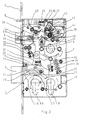
- a lock housing 1 Within a lock housing 1 are located in the FIG. 1 only the actual essential components that are necessary to explain the invention. All other components have been omitted. It will thus affect the function of the illustrated self-locking panic lock in any way.
- the left lateral conclusion of the lock housing 1 forms a face plate 2, which is broken by a control 5 of a case 4 and a bolt 3.
- a nut 9 which is equipped with a driver 21 which is connected via a rotatable connection 20 with a member 8 in operative connection. So the nut 9, the one shared Nut may be, remains in its basic position, this spring is loaded by a return spring 22. Likewise, a spring 26 is present, which loads the nut 9.
- first lock cylinder 18 Within the lock housing there is a first lock cylinder 18 and a second lock cylinder 19.
- the bolt 3 is guided with its locking shaft 6 via a guide pin 11 within a gate 10, which is located in the translatory member 8.
- the gate 10 is designed obliquely and has at their ends an upper latch 12 and a lower latching 13. It is clear that by the movement of the translatory member upwards in the drawing of FIG. 1 the bolt is pulled into the lock housing 1 due to the positive guidance on the guide pin 11 within the gate 10.
- case 4 The arranged above the bolt 3 case 4 is designed doppelschenkelig and in their geometrical dimensions wider than the bolt 3. Following the case 4, a case shaft 23 is present, which is loaded by a spring 24. By the spring 24, the case 4 is always pressed to the outside. In the presentation of the FIG. 1 is excluded case of bolt 3, the case 4 via a case locking member 27, ie the case 4 can not be pressed into the lock housing 1. At the same time, the double-legged trap 4 is stared in this position. Only when the translatory member 8 pulls the latch 3 in the lock housing, the latch shaft 23 is released via the case locking member 27, so that the case can be pressed into the lock housing 1.
- control element 5 which is also loaded by a spring 25.
- the spring 25 always pushes the control 5 out of the forend.
- the control element 5 has in the interior of the lock housing 1, a projection 29 which cooperates with a locking lug 28 which is located approximately at the end of the translatory member 8.
- the projection 29 engages with the locking lug 28 of the member 8.
- the member 8 can not sag back down into the lock housing 1, as it by the projection 29 in conjunction with the locking lug 28th held in this position.
- the control element 5 Only at the moment when the control element 5 comes into contact with a strike plate, not shown, the control element 5 is pressed into the lock housing against the spring 25. As a result, the control element 5 moves into the lock housing 1 and at the same time releases the link 8.
- the translatory member 8 is guided within the lock housing 1 by means of a guide pin 15 in an opening 14. If now causes a rotation of the locking lug on one of the lock cylinder 18 or 19 via a locking lug, not shown, this comes with a driver 16 or 17, depending on the use of the lock cylinder 18 or 19, together and thus raises the member 8 at.
- the two lock cylinders 18, 19 are arranged side by side. It is understood that with a change of the translatory member 8 is also possible, the lock cylinder 18, 19 to be arranged, for example, in a tubular frame lock on top of each other, the functions of the castle as such being preserved as a whole.
- the FIG. 1 moreover shows an electromagnet 37 whose electrical connections are connected to a plug-in contact 41 which is located inside the wall of the lock housing 1.
- the electromagnet 37 has a plunger 38 which, for example, with a driver 39th positively and positively connected.
- the driver 39 acts on a change 40, which is fastened to the nut 9.
- the solenoid 37 is energized, which is done by a radio signal or by a command transfer from a control room, for example, selectively open this door with the self-locking, electromechanical panic lock
- the plunger 38 is actuated by the electromagnet 37, so that a pivoting of the change 40 takes place.
- FIG. 2 Another variant of an electromechanical panic lock shows the FIG. 2 in which instead of the electromagnet 37, a motor 42 is installed with a corresponding gear. At the transmission there is a driver 44, which also acts upon rotation corresponding to the change 40 and thus allows a displacement of the translatory member 8 and thereby causes an opening of the door, not shown.
- FIGS. 1 and 2 In addition to the above-described mechanical functions and the structure of the self-locking panic lock according to the invention are the FIGS. 1 and 2 to remove further components. These are the sensors 20, 30, 31, 32. The sensors 20, 30, 31, 32 have different function monitoring tasks of the self-locking panic lock, which will be explained in more detail below.
- the sensor 20 dedektiert the Einbacter or the extended position of the control element 5. It comes, for example, a switching flag 36 to the shaft of the control element 5 and can thus ensure a safe Dedekt réelle the position of the control 5.
- the sensor 32 with its switching lug 33 is located in the vicinity of the bolt shank 6 and thus can dedektieren the retraction or extension of the bolt 3.
- the translatory element 8 Since the translatory element 8 is to be regarded as the central component, its position is also monitored, for example, by a sensor 31 with a corresponding switching lug 34. This shows that, for example, by the operation of one of the lock cylinder 18 or 19, the member 8 is moved upwards, resulting in a deduction on the sensor 31. At the same time, however, this position is also detected when the latch 3 is completely retracted into the lock housing 1. If the translatory member 8 arrived in its upper end position, so it hooks, as already described, with the locking lug 28 on the projection 29 of the control element 5. Upon actuation of the control element 5, that is, the control element 5 is pressed into the lock housing 1 , At the same time the dedication of the sensor 20 via the switching flag 36 is made.
- the actuation can also take place via the nut 9.
- this operation is also detected via a sensor 30 with the switching lug 35.
- microswitches 20, 30, 31, 32 with corresponding switching lugs 33, 34, 35, 36 were used.
- Hall generators or light barriers or other equivalent sensors it is also possible to use Hall generators or light barriers or other equivalent sensors.
Landscapes
- Physics & Mathematics (AREA)
- Electromagnetism (AREA)
- Business, Economics & Management (AREA)
- Emergency Management (AREA)
- Engineering & Computer Science (AREA)
- Structural Engineering (AREA)
- Lock And Its Accessories (AREA)
Applications Claiming Priority (1)
| Application Number | Priority Date | Filing Date | Title |
|---|---|---|---|
| DE102006060450A DE102006060450A1 (de) | 2006-12-19 | 2006-12-19 | Selbstverriegelndes, elektromechanisches Panikschloss |
Publications (2)
| Publication Number | Publication Date |
|---|---|
| EP1936075A2 true EP1936075A2 (fr) | 2008-06-25 |
| EP1936075A3 EP1936075A3 (fr) | 2010-06-23 |
Family
ID=39314924
Family Applications (1)
| Application Number | Title | Priority Date | Filing Date |
|---|---|---|---|
| EP07021274A Withdrawn EP1936075A3 (fr) | 2006-12-19 | 2007-10-31 | Serrure anti-panique électromécanique à verrouillage automatique |
Country Status (2)
| Country | Link |
|---|---|
| EP (1) | EP1936075A3 (fr) |
| DE (1) | DE102006060450A1 (fr) |
Cited By (8)
| Publication number | Priority date | Publication date | Assignee | Title |
|---|---|---|---|---|
| EP2703583A3 (fr) * | 2012-09-04 | 2015-03-11 | ASSA ABLOY Sicherheitstechnik GmbH | Dispositif de serrure pour vantail passif avec un dispositif de retrait de pêne comportant un poussoir à ressort d'actionnement du pêne |
| CN104818904A (zh) * | 2015-04-24 | 2015-08-05 | 浙江宏泰电子设备有限公司 | 嵌入式电机防盗锁 |
| EP2924202A1 (fr) * | 2014-03-25 | 2015-09-30 | ASSA ABLOY Sicherheitstechnik GmbH | Serrure de porte ou de fenêtre |
| EP3045623A1 (fr) * | 2015-01-19 | 2016-07-20 | MSL Schloss- und Beschlägefabrik AG | Dispositif de sécurisation de porte |
| CN108888223A (zh) * | 2018-09-25 | 2018-11-27 | 杭州老板电器股份有限公司 | 门体锁止组件及洗碗机 |
| EP3751079A1 (fr) * | 2019-06-11 | 2020-12-16 | dormakaba Deutschland GmbH | Serrure |
| CN112282520A (zh) * | 2020-10-31 | 2021-01-29 | 王允 | 一种自锁式安全开合装置 |
| CN113914714A (zh) * | 2021-11-09 | 2022-01-11 | 惠州市昊成工控科技有限公司 | 智能锁开关门检测方法及智能锁 |
Families Citing this family (3)
| Publication number | Priority date | Publication date | Assignee | Title |
|---|---|---|---|---|
| DE202009007735U1 (de) | 2009-05-30 | 2009-08-27 | Carl Fuhr Gmbh & Co. Kg | Schloß, insbesondere Zentralschloß für eine Schließanlage mit Mehrfachverriegelung |
| DE102017125087A1 (de) * | 2017-10-26 | 2019-05-02 | Maco Technologie Gmbh | Schloss |
| DE102024107618A1 (de) | 2024-03-18 | 2025-09-18 | Eco Schulte Gmbh & Co. Kg | Schloss mit daran anordbarer Energieversorgungseinrichtung |
Citations (9)
| Publication number | Priority date | Publication date | Assignee | Title |
|---|---|---|---|---|
| CH473298A (de) | 1967-06-09 | 1969-05-31 | Fiand F Gmbh | Rechts und links verwendbares Türschloss |
| DE19630972A1 (de) | 1995-07-31 | 1997-02-06 | Talleres Escoriaza Sa | Schloß |
| DE69405749T2 (de) | 1993-06-23 | 1998-03-26 | Luigi Riefolo | Ein elektromechanischer antrieb und ein elektrisch angetriebenes schloss und zutrittskontrollverfahren mit dieser vorrichtung |
| DE29905712U1 (de) | 1999-03-22 | 1999-06-02 | Hauff, Torsten, 10245 Berlin | Schloß mit Haupt- und Nebenschließung |
| DE19827516A1 (de) * | 1998-06-22 | 1999-12-23 | Dorma Gmbh & Co Kg | Selbstverriegelndes Panikschloß |
| DE19826869C1 (de) | 1998-06-17 | 2000-01-13 | Steinbach & Vollmann | Schloß für Hochsicherheitstüren |
| EP0882859B1 (fr) | 1997-06-05 | 2002-04-10 | Adolf Dolezel GmbH | Système de serrure et ferrure |
| DE19906271C2 (de) | 1999-02-15 | 2002-07-18 | Volker Sattler | Schloßkasten für eine Tür |
| DE10122466A1 (de) | 2001-05-09 | 2002-11-28 | Steinbach & Vollmann | Schloß |
Family Cites Families (5)
| Publication number | Priority date | Publication date | Assignee | Title |
|---|---|---|---|---|
| DE4344314C2 (de) * | 1993-12-23 | 1997-07-10 | Fuss Fritz Gmbh & Co | Verfahren zum Scharfschalten einer Einbruchmeldeanlage mittels eines Einsteckschlosses |
| DE9414137U1 (de) * | 1994-09-01 | 1994-10-20 | Steinbach & Vollmann GmbH & Co, 42579 Heiligenhaus | Schloß |
| DE19534609C2 (de) * | 1995-09-18 | 1998-09-24 | Fuss Fritz Gmbh & Co | Selbstverriegelndes Motorschloss |
| DE19626745C1 (de) * | 1996-07-03 | 1997-10-16 | Dorma Gmbh & Co Kg | Selbstverriegelndes Panikschloß |
| DE102004040692A1 (de) * | 2004-08-20 | 2006-03-09 | Dorma Gmbh + Co. Kg | Paniktürverschluss |
-
2006
- 2006-12-19 DE DE102006060450A patent/DE102006060450A1/de not_active Withdrawn
-
2007
- 2007-10-31 EP EP07021274A patent/EP1936075A3/fr not_active Withdrawn
Patent Citations (9)
| Publication number | Priority date | Publication date | Assignee | Title |
|---|---|---|---|---|
| CH473298A (de) | 1967-06-09 | 1969-05-31 | Fiand F Gmbh | Rechts und links verwendbares Türschloss |
| DE69405749T2 (de) | 1993-06-23 | 1998-03-26 | Luigi Riefolo | Ein elektromechanischer antrieb und ein elektrisch angetriebenes schloss und zutrittskontrollverfahren mit dieser vorrichtung |
| DE19630972A1 (de) | 1995-07-31 | 1997-02-06 | Talleres Escoriaza Sa | Schloß |
| EP0882859B1 (fr) | 1997-06-05 | 2002-04-10 | Adolf Dolezel GmbH | Système de serrure et ferrure |
| DE19826869C1 (de) | 1998-06-17 | 2000-01-13 | Steinbach & Vollmann | Schloß für Hochsicherheitstüren |
| DE19827516A1 (de) * | 1998-06-22 | 1999-12-23 | Dorma Gmbh & Co Kg | Selbstverriegelndes Panikschloß |
| DE19906271C2 (de) | 1999-02-15 | 2002-07-18 | Volker Sattler | Schloßkasten für eine Tür |
| DE29905712U1 (de) | 1999-03-22 | 1999-06-02 | Hauff, Torsten, 10245 Berlin | Schloß mit Haupt- und Nebenschließung |
| DE10122466A1 (de) | 2001-05-09 | 2002-11-28 | Steinbach & Vollmann | Schloß |
Cited By (12)
| Publication number | Priority date | Publication date | Assignee | Title |
|---|---|---|---|---|
| EP2703583A3 (fr) * | 2012-09-04 | 2015-03-11 | ASSA ABLOY Sicherheitstechnik GmbH | Dispositif de serrure pour vantail passif avec un dispositif de retrait de pêne comportant un poussoir à ressort d'actionnement du pêne |
| EP2703584A3 (fr) * | 2012-09-04 | 2015-03-11 | ASSA ABLOY Sicherheitstechnik GmbH | Dispositif de serrure pour vantail passif doté d'un dispositif d'actionnement motorisé |
| EP2703586A3 (fr) * | 2012-09-04 | 2015-03-11 | ASSA ABLOY Sicherheitstechnik GmbH | Dispositif de serrure pour vantail passif doté d'un dispositif de détection |
| EP2703586B1 (fr) | 2012-09-04 | 2018-10-24 | ASSA ABLOY Sicherheitstechnik GmbH | Dispositif de serrure pour vantail passif doté d'un dispositif de détection |
| EP2924202A1 (fr) * | 2014-03-25 | 2015-09-30 | ASSA ABLOY Sicherheitstechnik GmbH | Serrure de porte ou de fenêtre |
| EP3045623A1 (fr) * | 2015-01-19 | 2016-07-20 | MSL Schloss- und Beschlägefabrik AG | Dispositif de sécurisation de porte |
| CN104818904A (zh) * | 2015-04-24 | 2015-08-05 | 浙江宏泰电子设备有限公司 | 嵌入式电机防盗锁 |
| CN108888223A (zh) * | 2018-09-25 | 2018-11-27 | 杭州老板电器股份有限公司 | 门体锁止组件及洗碗机 |
| CN108888223B (zh) * | 2018-09-25 | 2024-04-09 | 杭州老板电器股份有限公司 | 门体锁止组件及洗碗机 |
| EP3751079A1 (fr) * | 2019-06-11 | 2020-12-16 | dormakaba Deutschland GmbH | Serrure |
| CN112282520A (zh) * | 2020-10-31 | 2021-01-29 | 王允 | 一种自锁式安全开合装置 |
| CN113914714A (zh) * | 2021-11-09 | 2022-01-11 | 惠州市昊成工控科技有限公司 | 智能锁开关门检测方法及智能锁 |
Also Published As
| Publication number | Publication date |
|---|---|
| EP1936075A3 (fr) | 2010-06-23 |
| DE102006060450A1 (de) | 2008-06-26 |
Similar Documents
| Publication | Publication Date | Title |
|---|---|---|
| EP0096400B1 (fr) | Installation de fermeture pour la consolidation des portes | |
| EP2385197B1 (fr) | Serrure | |
| DE102011008213A1 (de) | Türschlossvorrichtung und Verfahren zum Öffnen einer Türschlossvorrichtung | |
| DE102011000553A1 (de) | Schlosssystem für eine zweiflügelige Türanlage mit Panikfunktion | |
| DE19626745C1 (de) | Selbstverriegelndes Panikschloß | |
| EP1441091A2 (fr) | Serrure de porte à déverrouillage de secours | |
| DE102011051952A1 (de) | Fernaktivierbares selbstverriegelndes Türschloss | |
| DE102006060450A1 (de) | Selbstverriegelndes, elektromechanisches Panikschloss | |
| EP2390445B1 (fr) | Serrure | |
| EP2385196B1 (fr) | Serrure | |
| DE19546467C1 (de) | Sicherheitsschloß | |
| EP2339096B1 (fr) | Serrure à crémone dotée d'une fonction anti-panique et d'un verrouillage multiple | |
| EP1936073A2 (fr) | Serrure anti-panique à verrouillage automatique | |
| EP2385194B1 (fr) | Serrure | |
| EP3628801B1 (fr) | Dispositif de fermeture pour une porte et procédé pour ouvrir une porte | |
| EP1908899A2 (fr) | Système de verrouillage | |
| EP3543437B1 (fr) | Dispositif formant serrure pourvu d'une serrure pour une porte à battants mobiles | |
| DE10122466A1 (de) | Schloß | |
| EP1936076B1 (fr) | Serrure anti-panique à verrouillage automatique | |
| EP0697490A1 (fr) | Dispositif d'actionnement d'un pêne commandé | |
| DE102005001312B4 (de) | Fernbetätigter Türöffner | |
| EP1936074A2 (fr) | Serrure anti-panique à verrouillage automatique, et procédé d'utilisation d'une serrure anti-panique à verrouillage automatique | |
| DE102023122178A1 (de) | Automatisch verriegelndes Treibstangenschloss | |
| DE102020205673B3 (de) | Selbstverriegelndes Schloss | |
| EP2169155B1 (fr) | Serrure |
Legal Events
| Date | Code | Title | Description |
|---|---|---|---|
| PUAI | Public reference made under article 153(3) epc to a published international application that has entered the european phase |
Free format text: ORIGINAL CODE: 0009012 |
|
| AK | Designated contracting states |
Kind code of ref document: A2 Designated state(s): AT BE BG CH CY CZ DE DK EE ES FI FR GB GR HU IE IS IT LI LT LU LV MC MT NL PL PT RO SE SI SK TR |
|
| AX | Request for extension of the european patent |
Extension state: AL BA HR MK RS |
|
| PUAL | Search report despatched |
Free format text: ORIGINAL CODE: 0009013 |
|
| AK | Designated contracting states |
Kind code of ref document: A3 Designated state(s): AT BE BG CH CY CZ DE DK EE ES FI FR GB GR HU IE IS IT LI LT LU LV MC MT NL PL PT RO SE SI SK TR |
|
| AX | Request for extension of the european patent |
Extension state: AL BA HR MK RS |
|
| RAP1 | Party data changed (applicant data changed or rights of an application transferred) |
Owner name: DORMA GMBH + CO. KG |
|
| 17P | Request for examination filed |
Effective date: 20101223 |
|
| AKX | Designation fees paid |
Designated state(s): AT BE BG CH CY CZ DE DK EE ES FI FR GB GR HU IE IS IT LI LT LU LV MC MT NL PL PT RO SE SI SK TR |
|
| RAP1 | Party data changed (applicant data changed or rights of an application transferred) |
Owner name: DORMA DEUTSCHLAND GMBH |
|
| RAP1 | Party data changed (applicant data changed or rights of an application transferred) |
Owner name: DORMAKABA DEUTSCHLAND GMBH |
|
| STAA | Information on the status of an ep patent application or granted ep patent |
Free format text: STATUS: EXAMINATION IS IN PROGRESS |
|
| 17Q | First examination report despatched |
Effective date: 20180604 |
|
| STAA | Information on the status of an ep patent application or granted ep patent |
Free format text: STATUS: THE APPLICATION IS DEEMED TO BE WITHDRAWN |
|
| 18D | Application deemed to be withdrawn |
Effective date: 20181016 |