EP1936103A2 - System zum Betätigen einer Jalousie, eines Rollladens oder anderer beweglicher Mittel zum Schließen einer Tür oder eines Fensters - Google Patents
System zum Betätigen einer Jalousie, eines Rollladens oder anderer beweglicher Mittel zum Schließen einer Tür oder eines Fensters Download PDFInfo
- Publication number
- EP1936103A2 EP1936103A2 EP07122510A EP07122510A EP1936103A2 EP 1936103 A2 EP1936103 A2 EP 1936103A2 EP 07122510 A EP07122510 A EP 07122510A EP 07122510 A EP07122510 A EP 07122510A EP 1936103 A2 EP1936103 A2 EP 1936103A2
- Authority
- EP
- European Patent Office
- Prior art keywords
- door
- electro
- window
- electrical
- motor apparatus
- Prior art date
- Legal status (The legal status is an assumption and is not a legal conclusion. Google has not performed a legal analysis and makes no representation as to the accuracy of the status listed.)
- Granted
Links
Images




Classifications
-
- E—FIXED CONSTRUCTIONS
- E06—DOORS, WINDOWS, SHUTTERS, OR ROLLER BLINDS IN GENERAL; LADDERS
- E06B—FIXED OR MOVABLE CLOSURES FOR OPENINGS IN BUILDINGS, VEHICLES, FENCES OR LIKE ENCLOSURES IN GENERAL, e.g. DOORS, WINDOWS, BLINDS, GATES
- E06B9/00—Screening or protective devices for wall or similar openings, with or without operating or securing mechanisms; Closures of similar construction
- E06B9/24—Screens or other constructions affording protection against light, especially against sunshine; Similar screens for privacy or appearance; Slat blinds
- E06B9/26—Lamellar or like blinds, e.g. venetian blinds
- E06B9/28—Lamellar or like blinds, e.g. venetian blinds with horizontal lamellae, e.g. non-liftable
- E06B9/30—Lamellar or like blinds, e.g. venetian blinds with horizontal lamellae, e.g. non-liftable liftable
- E06B9/32—Operating, guiding, or securing devices therefor
-
- E—FIXED CONSTRUCTIONS
- E06—DOORS, WINDOWS, SHUTTERS, OR ROLLER BLINDS IN GENERAL; LADDERS
- E06B—FIXED OR MOVABLE CLOSURES FOR OPENINGS IN BUILDINGS, VEHICLES, FENCES OR LIKE ENCLOSURES IN GENERAL, e.g. DOORS, WINDOWS, BLINDS, GATES
- E06B9/00—Screening or protective devices for wall or similar openings, with or without operating or securing mechanisms; Closures of similar construction
- E06B9/56—Operating, guiding or securing devices or arrangements for roll-type closures; Spring drums; Tape drums; Counterweighting arrangements therefor
- E06B9/68—Operating devices or mechanisms, e.g. with electric drive
-
- E—FIXED CONSTRUCTIONS
- E06—DOORS, WINDOWS, SHUTTERS, OR ROLLER BLINDS IN GENERAL; LADDERS
- E06B—FIXED OR MOVABLE CLOSURES FOR OPENINGS IN BUILDINGS, VEHICLES, FENCES OR LIKE ENCLOSURES IN GENERAL, e.g. DOORS, WINDOWS, BLINDS, GATES
- E06B9/00—Screening or protective devices for wall or similar openings, with or without operating or securing mechanisms; Closures of similar construction
- E06B9/24—Screens or other constructions affording protection against light, especially against sunshine; Similar screens for privacy or appearance; Slat blinds
- E06B9/26—Lamellar or like blinds, e.g. venetian blinds
- E06B9/264—Combinations of lamellar blinds with roller shutters, screen windows, windows, or double panes; Lamellar blinds with special devices
- E06B2009/2643—Screens between double windows
Definitions
- the present invention relates to the field of doors or windows having motor driven closing means such as for example Venetian blinds, plissé, roller blinds or roller shutter windows, and in particular it refers to an actuating system for such closing means.
- Doors or windows provided with a motor apparatus for moving closing means such as the blades of a Venetian blind are essentially divided in two types, as regards the manufacture of the actuating means and the actuating mode.
- a first type envisages including all the electrical and electronic devices that command and control the motor apparatus in an element of the door or window frame. Only an actuating device is fixed outside the door or window, typically consisting of at least two electrical contacts or switches, that the user must actuate to activate the motor control and command devices in the desired mode.
- a second type envisages the use of a remote control for activating the motor control and command devices.
- a remote control for activating the motor control and command devices.
- the command and control devices of the motor apparatus provided in the door or window frame must be connected to the mains to be powered. Since the motor apparatus operates at low voltage, a transformer should further be provided to reduce the mains voltage to the motor operating voltage.
- the electrical system of a room must be designed and modified so as to always be provided with a current outlet in the vicinity of a motor driven door or window.
- each motor apparatus is associated to its own command and control devices, all integrated in the door or window frame. In the presence of multiple window and door frames, these devices must therefore be multiplied by the number of motor apparatus used.
- the motor apparatus and the relevant electrical/electronic devices are located inside a sealed air space. If one of these elements undergoes failure, it is necessary to remove the entire blind and one is often forced to send it to the manufacturer for repair and reassembly.
- command device comprising electrical supply means of the electro-motor apparatus and electronic means to control said apparatus, said command device being transportable by a user and having an electrical outlet element suitable for coupling with said plug element for electrically connecting said supply means and said electronic means for controlling the electro-motor apparatus.
- the object of the present invention is to obviate the limits and disadvantages mentioned above and propose a system for actuating motor driven doors or windows even more comfortable to use and with very limited overall dimensions.
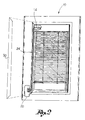
- figure 1 shows an overall view of a Venetian blind and of a relevant control device according to the present invention
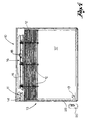
- figure 2 shows a perspective view of a Venetian blind without a glass locking frame
- figure 3 shows a view of a portion of a Venetian blind in a second embodiment thereof, wherein the actuating device is shown excessively enlarged;
- figure 4 shows a cutaway view of a Venetian blind at the level of the electro-motor apparatus
- figure 5 shows the contact holder plate of the actuating system
- figure 6 shows the back side of the control device
- figure 7 shows the front side of the control device
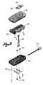
- figure 8 shows a perspective exploded view of the contact holder plate
- figure 9 shows a perspective exploded view of the control device.
- the actuating system of the present invention is advantageously applicable to a Venetian blind with double glazing, that is, a blind wherein the adjustable blades 12 and the relevant moving means are arranged in a sealed air space delimited by two glasses 10'.
- the invention in any case is applicable in the same way to other types of doors or windows, such as roller shutters, provided with a motor driven apparatus for moving the closing means of such doors or windows.
- the system for actuating the Venetian blind 10 comprises an electro-motor apparatus 11 ( Figure 4 ) suitable for moving in an automated manner the rise and the lowering of blades 12 of said Venetian blind.
- the electro-motor apparatus 11 is seated in portion of a frame 13 supporting blind 10.
- the electro-motor apparatus 11 comprises a motor-reduction gear 14 coupled to a roller or shaft 15 for winding/unwinding ropes 12' for moving blades 12.
- Motor-reduction gear 14 and shaft 15 are located in a seat 16 with horizontal extension obtained in a box or a top portion 17 of frame 13 of the blind.
- shaft 15 is associated to a mechanical stop device 18 suitable for stopping the movement of said shaft 15 when the blind reaches a predetermined height position.
- Seat 16 has no further electrical or electronic device for supplying and controlling the electro-motor apparatus 11.
- a contact holder plate 19 is fixed to frame 13 of blind 10, or to one of glasses 10', in any case in a position comfortably accessible by a user, wherein at least two electrical contacts 19' electrically connected to the motor-reduction gear 14 are buried.
- the contact holder plate 19 is suitable for electrically coupling to a control device 20 comprising electrical supply means 22 of the motor-reduction gear 14 and electronic control means 24 of said gear.
- the control device 20 is shaped as a usual remote control, that is, it is a device included in a box shaped container 26 separate from blind 10 and that can be carried by a user.
- the control device 20 is provided with electrical contacts 23 suitable for electrically coupling to the electrical contacts 19' of plate 19 for electrically connecting the supply means and the electronic control means to the electro-motor apparatus 11.
- the contact holder plate 19 is glued to glass 10' ( Figures 3 , 4 ), screwed to frame 13 ( Figure 1 ) or to a simple glass locking frame 30 removably coupled to the frame ( figure 2 ), according to the needs.
- Plate 19 is connected to the motor-reduction gear 14 by electrical conductors 24, for example shaped as a plate, which extend along an external element 25 of the blind frame and which can advantageously be hidden by the glass locking frame 30, so as to be substantially hidden to sight.
- the electrical conductors 24 are associated to suitable sealing means suitable for preventing any air passage between the inside of the air space and the external environment.
- the contact holder plate 19 and the control device 20 can be magnetically coupled to each other so as to obtain the electrical connection between the respective electrical contacts 19', 23.
- the matching between plate 19 and control device 20 that allows establishing an electrical connection between the respective electrical contacts is given by a magnetic field that attracts the control device to the plate.
- the contact holder plate 19 and/or the control device 20 are provided with a magnet suitable for attracting an element made of a ferromagnetic material associated to the control device and/or to the contact holder plate.
- the contact holder plate 19 is provided with two magnets 29 suitable for coupling with corresponding plates of ferromagnetic material 23 associated to the control device 20 and acting as electrical contacts.
- each electrical contact 19' of plate 19 is placed in contact with a respective magnet 29 so as to make a single conductor element therewith.
- magnets 29 have the dual function of coupling means between the control device 20 and plate 19 and electrical conduction means between contacts 23 of the control device and contacts 19' of plate 19. It should be noted that the presence of the electrical contacts 19' is suitable because it would be complicated to connect, for example by welding, the electrical conductors 24 directly to magnets 29.
- the magnetic coupling is such as to overcome the weight force of the control device 20, which remains fixed to plate 19 as soon as it is moved near it, without the need of being manually supported by the user and without the use of further coupling means.
- the ferromagnetic material of plates 23 for example is ferric phosphate.
- the contact holder plate 19 comprises a base 30 suitable for being fixed, for example by a two-faced sheet 31, to the glass or to the frame of the door or window. Two seats 32 are obtained in said base 30, in each there is seated an electrical contact 19' and a magnet 29 superimposed thereto.
- the electrical contacts 19' exhibit a laminar shape and are welded to conductors 24 that protrude from plate 19. Magnets 29 also exhibit a flat shape as a tablet.
- Plate 19 is completed by a cover 33 fixed to base 30, for example by screws 34. At the level of magnets 29, the cover has respective windows 35 wherethrough the outer surface of magnets 29 protrudes, suitable for contacting plates 23 of the control device.
- Plate 19 therefore has a very small thickness, for example in the range of few millimetres. Magnets 29 are almost buried in plate 19, that is, they do not considerably protrude from the front surface of the plate itself
- Base 30 and cover 33 of plate 19 may also be made of plastic material or rubber, for example transparent polycarbonate, so as to hide as much as possible with the frame or the glass.
- plates 23 of the control device 20 have a flat shape so as to not considerably protrude from the box shaped container 26 of the control device 20.
- plates 23 have a contact surface sufficiently wide to allow the immediate centring and thus locking between control device 20 and plate 19.
- the user needs not be careful to the alignment between magnets 29 of plate 19 and plates 23 of the control device; instead, as the user approaches the control device 20 to plate 19, so that the side of the box shaped container 26 carrying plates 23 faces plate 19, the magnetic field force makes the two parts conjugate immediately in a correct manner.
- plates 23 are fixed to the box shaped body 26 of the control device 20 by contact screws 40.
- the contact screws penetrate in said box shaped body 26 and are electrically connected to the power 22 and control 24 means of the motor apparatus.
- said screws 40 are screwed to locking washers 41 that fasten the screws themselves to a pair of electrical cables 42 that connect the electrical contacts 23, 40 to the supply 22 and control 24 means of the motor apparatus provided into the box shaped body 26.
- the power supply means 22 comprise at least one electrical battery, preferably of the rechargeable type.
- the control device is provided with an electrical plug 27 for the connection to a battery charger (not shown).
- the electronic control means 24 comprise:
- the means with self-learning function allow storing a travel end position subsequent to the detection of a current peak due to the activation of the mechanical stop device 18.
- the circuit for detecting the current absorbed is provided for interrupting the supply to the electro-motor apparatus when the absorbed current exceeds a predetermined threshold value.
- control device 20 comprises at least one electrical switch actuable by a user by a key or a button for activating/deactivating an electrical connection between the power supply means and/or the electronic control means of the control device and the electro-motor gear 14.
- a key 28 may be provided for controlling the rise of blind 10 and a key 28' for controlling the lowering of the blind.
- the control device 20 is further provided with light signalling devices 52 for indicating, for example, the correct movement of the blind rising or lowering, or the status of battery 27.
- the actuating system with magnetic coupling allows a user to press a blind rise or lowering key and thanks to the fact that the control device remains autonomously connected to the contact holder plate 19, leaving the control device while the blind is moved, for example for controlling other blinds.
- control device 20 can be disconnected from plate 19, but can also remain connected thereto.
- the actuating system described allows obtaining the following advantages.
- the electronic and supply part is located in a usual box shaped container external to the blind and can be easily fixed in the event of a failure or replaced without intervening on the blind.
- the electrical connection of the electro-motor apparatus to the supply is greatly simplified compared to the current blinds, where electrical conductors to connect to the mains protrude from the blind. There is not the constraint of having to provide an outlet in the proximity of the motor driven blind.
- control device with rechargeable batteries allows avoiding the use of heavy and bulky voltage transformers.
- the blind therefore exhibits the known use comfort of a motor driven movement but is simpler and more expensive to make, reliable over time and in any case easy to maintain.
Landscapes
- Engineering & Computer Science (AREA)
- Structural Engineering (AREA)
- Architecture (AREA)
- Civil Engineering (AREA)
- Operating, Guiding And Securing Of Roll- Type Closing Members (AREA)
- Blinds (AREA)
- Power-Operated Mechanisms For Wings (AREA)
Priority Applications (2)
| Application Number | Priority Date | Filing Date | Title |
|---|---|---|---|
| SI200730362T SI1936103T1 (sl) | 2006-12-13 | 2007-12-06 | Sistem za proženje rolete s prenosno krmilno enoto ki vsebuje vir električnega napajanja |
| PL07122510T PL1936103T3 (pl) | 2006-12-13 | 2007-12-06 | Układ do uruchamiania żaluzji rolkowej z przenośnym urządzeniem sterującym zawierający zasilanie energią elektryczną |
Applications Claiming Priority (1)
| Application Number | Priority Date | Filing Date | Title |
|---|---|---|---|
| IT000219A ITBS20060219A1 (it) | 2006-12-13 | 2006-12-13 | Sistema di attuazione di una tenda alla veneziana, di una persiana avvolgibile o di altri mezzi movibili di chiusura di una porta o finestra |
Publications (3)
| Publication Number | Publication Date |
|---|---|
| EP1936103A2 true EP1936103A2 (de) | 2008-06-25 |
| EP1936103A3 EP1936103A3 (de) | 2009-02-18 |
| EP1936103B1 EP1936103B1 (de) | 2010-07-21 |
Family
ID=39185903
Family Applications (1)
| Application Number | Title | Priority Date | Filing Date |
|---|---|---|---|
| EP07122510A Active EP1936103B1 (de) | 2006-12-13 | 2007-12-06 | System zum Betätigen eines Rollladens mit einer tragbaren Steuereinheit mit elektrischer Energiequelle |
Country Status (8)
| Country | Link |
|---|---|
| EP (1) | EP1936103B1 (de) |
| AT (1) | ATE474993T1 (de) |
| DE (1) | DE602007007878D1 (de) |
| ES (1) | ES2348796T3 (de) |
| IT (1) | ITBS20060219A1 (de) |
| PL (1) | PL1936103T3 (de) |
| PT (1) | PT1936103E (de) |
| SI (1) | SI1936103T1 (de) |
Cited By (8)
| Publication number | Priority date | Publication date | Assignee | Title |
|---|---|---|---|---|
| AU2013100229B4 (en) * | 2009-01-13 | 2013-07-04 | Automatic Technology (Australia) Pty Ltd | Door Operator Unit Having a Motor Unit Housing and an Electric Component Housing |
| WO2013158347A1 (en) * | 2012-04-18 | 2013-10-24 | Homerun Holdings Corporation | Spring tensioned roll type motorized blind or shade system having an external power supply or motor controller |
| EP2700783A1 (de) * | 2012-08-24 | 2014-02-26 | Stylianos KOUPOURTIDIS | Magnetischer Mechanismus zur Jalousienbetätigung zwischen Doppelverglasung unter Verwendung eines kleinen elektrischen Gleichstrommotors |
| US9241590B2 (en) | 2013-11-18 | 2016-01-26 | Gordon's Window Decor, Inc. | Quick-release control system for architectural opening covering |
| AU2010200132B2 (en) * | 2009-01-13 | 2016-07-07 | Automatic Technology (Australia) Pty Ltd | Door Operator Unit Having a Motor Unit Housing and an Electric Component Housing |
| IT201900015788A1 (it) * | 2019-09-06 | 2021-03-06 | Pellini Spa | Vetrocamera dotata di un modulo di memoria |
| US11957261B2 (en) | 2017-04-28 | 2024-04-16 | Lutron Technology Company Llc | Window treatment mounting bracket |
| IT202300013998A1 (it) * | 2023-07-05 | 2025-01-05 | Sun Bell S R L | Sistema di attuazione per una tenda mobile motorizzata |
Families Citing this family (1)
| Publication number | Priority date | Publication date | Assignee | Title |
|---|---|---|---|---|
| US11462871B2 (en) | 2019-10-22 | 2022-10-04 | Hunter Douglas Inc. | Power supply box for use with an architectural-structure covering |
Citations (2)
| Publication number | Priority date | Publication date | Assignee | Title |
|---|---|---|---|---|
| WO2003095781A1 (en) | 2002-05-13 | 2003-11-20 | Ozroll Ip Pty. Ltd. | Improvements to roller shutters |
| US20060076113A1 (en) | 2004-10-12 | 2006-04-13 | Sun Eun Park | Pair glass window and door system equipped with remote controllable auto blind |
Family Cites Families (6)
| Publication number | Priority date | Publication date | Assignee | Title |
|---|---|---|---|---|
| US3810258A (en) * | 1972-07-11 | 1974-05-07 | W Mathauser | Quick connect electrical coupler |
| DE4008939A1 (de) * | 1990-03-20 | 1991-09-26 | Elero Antrieb Sonnenschutz | Elektronische rolladensteuerung mit steckbarem steuerteil |
| WO2002064938A1 (de) * | 2001-02-15 | 2002-08-22 | Alfred Schellenberg Gmbh | Vorrichtung und verfahren zum ansteuern eines gurtes für einen rolladen |
| FR2826517B1 (fr) * | 2001-06-20 | 2004-03-12 | Somfy | Dispositif d'alimentation pour store motorise ou similaire |
| CN2637690Y (zh) * | 2003-07-25 | 2004-09-01 | 亿丰综合工业股份有限公司 | 易于更换电池的电动窗帘 |
| US7026789B2 (en) * | 2003-12-23 | 2006-04-11 | Motorola, Inc. | Charging system for electronic devices |
-
2006
- 2006-12-13 IT IT000219A patent/ITBS20060219A1/it unknown
-
2007
- 2007-12-06 AT AT07122510T patent/ATE474993T1/de not_active IP Right Cessation
- 2007-12-06 ES ES07122510T patent/ES2348796T3/es active Active
- 2007-12-06 SI SI200730362T patent/SI1936103T1/sl unknown
- 2007-12-06 EP EP07122510A patent/EP1936103B1/de active Active
- 2007-12-06 DE DE602007007878T patent/DE602007007878D1/de active Active
- 2007-12-06 PL PL07122510T patent/PL1936103T3/pl unknown
- 2007-12-06 PT PT07122510T patent/PT1936103E/pt unknown
Patent Citations (2)
| Publication number | Priority date | Publication date | Assignee | Title |
|---|---|---|---|---|
| WO2003095781A1 (en) | 2002-05-13 | 2003-11-20 | Ozroll Ip Pty. Ltd. | Improvements to roller shutters |
| US20060076113A1 (en) | 2004-10-12 | 2006-04-13 | Sun Eun Park | Pair glass window and door system equipped with remote controllable auto blind |
Cited By (16)
| Publication number | Priority date | Publication date | Assignee | Title |
|---|---|---|---|---|
| AU2013100229B4 (en) * | 2009-01-13 | 2013-07-04 | Automatic Technology (Australia) Pty Ltd | Door Operator Unit Having a Motor Unit Housing and an Electric Component Housing |
| AU2010200132B2 (en) * | 2009-01-13 | 2016-07-07 | Automatic Technology (Australia) Pty Ltd | Door Operator Unit Having a Motor Unit Housing and an Electric Component Housing |
| WO2013158347A1 (en) * | 2012-04-18 | 2013-10-24 | Homerun Holdings Corporation | Spring tensioned roll type motorized blind or shade system having an external power supply or motor controller |
| EP2700783A1 (de) * | 2012-08-24 | 2014-02-26 | Stylianos KOUPOURTIDIS | Magnetischer Mechanismus zur Jalousienbetätigung zwischen Doppelverglasung unter Verwendung eines kleinen elektrischen Gleichstrommotors |
| US9241590B2 (en) | 2013-11-18 | 2016-01-26 | Gordon's Window Decor, Inc. | Quick-release control system for architectural opening covering |
| US10030443B2 (en) | 2013-11-18 | 2018-07-24 | Gordon's Window Decor, Inc. | Quick-release control system for architectural opening covering |
| US11957261B2 (en) | 2017-04-28 | 2024-04-16 | Lutron Technology Company Llc | Window treatment mounting bracket |
| CN114302999A (zh) * | 2019-09-06 | 2022-04-08 | 佩利尼股份公司 | 具有存储器模块的隔热玻璃单元 |
| WO2021044226A1 (en) * | 2019-09-06 | 2021-03-11 | Pellini S.P.A. | An insulated glazing unit with a memory module |
| IL290676B1 (en) * | 2019-09-06 | 2023-08-01 | Pellini Spa | Insulated glazing unit with memory module |
| IL290676B2 (en) * | 2019-09-06 | 2023-12-01 | Pellini Spa | An insulated glazing unit with a memory module |
| IT201900015788A1 (it) * | 2019-09-06 | 2021-03-06 | Pellini Spa | Vetrocamera dotata di un modulo di memoria |
| CN114302999B (zh) * | 2019-09-06 | 2024-10-29 | 佩利尼股份公司 | 具有存储器模块的隔热玻璃单元 |
| US12503910B2 (en) | 2019-09-06 | 2025-12-23 | Pellini S.P.A. | Insulated glazing units with memory modules |
| IT202300013998A1 (it) * | 2023-07-05 | 2025-01-05 | Sun Bell S R L | Sistema di attuazione per una tenda mobile motorizzata |
| WO2025008684A1 (en) * | 2023-07-05 | 2025-01-09 | Sun Bell S.R.L. | Actuation system for a motorized movable blind |
Also Published As
| Publication number | Publication date |
|---|---|
| ITBS20060219A1 (it) | 2008-06-14 |
| PT1936103E (pt) | 2010-10-21 |
| SI1936103T1 (sl) | 2010-11-30 |
| PL1936103T3 (pl) | 2010-12-31 |
| EP1936103A3 (de) | 2009-02-18 |
| DE602007007878D1 (de) | 2010-09-02 |
| EP1936103B1 (de) | 2010-07-21 |
| ES2348796T3 (es) | 2010-12-14 |
| ATE474993T1 (de) | 2010-08-15 |
Similar Documents
| Publication | Publication Date | Title |
|---|---|---|
| EP1936103B1 (de) | System zum Betätigen eines Rollladens mit einer tragbaren Steuereinheit mit elektrischer Energiequelle | |
| CN100504016C (zh) | 控制可移动障碍物操作的方法 | |
| US12065876B2 (en) | Motorized window treatment | |
| US9959997B2 (en) | Remote controlled switch cover | |
| EP2010745B1 (de) | Federunterstützter mechanismus zur anhebung und absenkung einer last | |
| CN101715313A (zh) | 用于马桶的自动座圈和/或盖板组件 | |
| US8561348B2 (en) | Security automatic garage door closer | |
| JP5264617B2 (ja) | 巻き取り用駆動装置、並びに、巻き取り装置 | |
| CA2590862A1 (en) | Automated shutter control | |
| US20150026890A1 (en) | Emergency power supply device for an electromotive furniture drive for a piece of furniture, electromotive furniture drive, and a corresponding piece of furniture | |
| JP2016511963A (ja) | スイッチング装置 | |
| CN114901108B (zh) | 机动驱动装置、掩蔽或日光保护装置及家庭自动化设备 | |
| US20230009409A1 (en) | Electromechanical actuator for blackout or sun-shading device and blackout or sun-shading installation comprising such an actuator | |
| KR100706328B1 (ko) | 슬라이드 도어의 전동 개폐장치 | |
| KR101541735B1 (ko) | 슬라이딩 자동문 구동 장치 | |
| CN115735045A (zh) | 包括电动设备的遮蔽设备 | |
| US20070271850A1 (en) | Self-contained motorized lift-slide panel | |
| EP0878600A3 (de) | Elektromotorisch angetriebene Kippöffnungsvorrichtung für Fenster, Türen oder dergleichen | |
| CN103997830B (zh) | 开关设备及其控制方法 | |
| CN110259315B (zh) | 门锁用电机驱动机构 | |
| ES2246193T1 (es) | Dispositivo de alimentacion electrica de una cerradura motorizada. | |
| EP3400604B1 (de) | Ferngesteuerte schalterabdeckung | |
| CN210659668U (zh) | 门锁用电机驱动机构 | |
| JP4268600B2 (ja) | 引戸開閉装置 | |
| JP3087940U (ja) | 警報装置 |
Legal Events
| Date | Code | Title | Description |
|---|---|---|---|
| PUAI | Public reference made under article 153(3) epc to a published international application that has entered the european phase |
Free format text: ORIGINAL CODE: 0009012 |
|
| AK | Designated contracting states |
Kind code of ref document: A2 Designated state(s): AT BE BG CH CY CZ DE DK EE ES FI FR GB GR HU IE IS IT LI LT LU LV MC MT NL PL PT RO SE SI SK TR |
|
| AX | Request for extension of the european patent |
Extension state: AL BA HR MK RS |
|
| PUAL | Search report despatched |
Free format text: ORIGINAL CODE: 0009013 |
|
| AK | Designated contracting states |
Kind code of ref document: A3 Designated state(s): AT BE BG CH CY CZ DE DK EE ES FI FR GB GR HU IE IS IT LI LT LU LV MC MT NL PL PT RO SE SI SK TR |
|
| AX | Request for extension of the european patent |
Extension state: AL BA HR MK RS |
|
| 17P | Request for examination filed |
Effective date: 20090814 |
|
| 17Q | First examination report despatched |
Effective date: 20090909 |
|
| AKX | Designation fees paid |
Designated state(s): AT BE BG CH CY CZ DE DK EE ES FI FR GB GR HU IE IS IT LI LT LU LV MC MT NL PL PT RO SE SI SK TR |
|
| GRAP | Despatch of communication of intention to grant a patent |
Free format text: ORIGINAL CODE: EPIDOSNIGR1 |
|
| RTI1 | Title (correction) |
Free format text: SYSTEM FOR ACTUATING A ROLLER SHUTTER WITH A PORTABLE CONTROL DEVICE CONTAINING THE ELECTRIC ENERGY SUPPLY |
|
| GRAS | Grant fee paid |
Free format text: ORIGINAL CODE: EPIDOSNIGR3 |
|
| GRAA | (expected) grant |
Free format text: ORIGINAL CODE: 0009210 |
|
| AK | Designated contracting states |
Kind code of ref document: B1 Designated state(s): AT BE BG CH CY CZ DE DK EE ES FI FR GB GR HU IE IS IT LI LT LU LV MC MT NL PL PT RO SE SI SK TR |
|
| REG | Reference to a national code |
Ref country code: GB Ref legal event code: FG4D |
|
| REG | Reference to a national code |
Ref country code: CH Ref legal event code: EP |
|
| REG | Reference to a national code |
Ref country code: IE Ref legal event code: FG4D |
|
| REF | Corresponds to: |
Ref document number: 602007007878 Country of ref document: DE Date of ref document: 20100902 Kind code of ref document: P |
|
| REG | Reference to a national code |
Ref country code: GR Ref legal event code: EP Ref document number: 20100402020 Country of ref document: GR |
|
| REG | Reference to a national code |
Ref country code: RO Ref legal event code: EPE |
|
| REG | Reference to a national code |
Ref country code: NL Ref legal event code: T3 |
|
| REG | Reference to a national code |
Ref country code: ES Ref legal event code: FG2A Effective date: 20101130 |
|
| LTIE | Lt: invalidation of european patent or patent extension |
Effective date: 20100721 |
|
| REG | Reference to a national code |
Ref country code: PL Ref legal event code: T3 |
|
| PG25 | Lapsed in a contracting state [announced via postgrant information from national office to epo] |
Ref country code: LT Free format text: LAPSE BECAUSE OF FAILURE TO SUBMIT A TRANSLATION OF THE DESCRIPTION OR TO PAY THE FEE WITHIN THE PRESCRIBED TIME-LIMIT Effective date: 20100721 Ref country code: AT Free format text: LAPSE BECAUSE OF FAILURE TO SUBMIT A TRANSLATION OF THE DESCRIPTION OR TO PAY THE FEE WITHIN THE PRESCRIBED TIME-LIMIT Effective date: 20100721 Ref country code: FI Free format text: LAPSE BECAUSE OF FAILURE TO SUBMIT A TRANSLATION OF THE DESCRIPTION OR TO PAY THE FEE WITHIN THE PRESCRIBED TIME-LIMIT Effective date: 20100721 |
|
| PG25 | Lapsed in a contracting state [announced via postgrant information from national office to epo] |
Ref country code: IS Free format text: LAPSE BECAUSE OF FAILURE TO SUBMIT A TRANSLATION OF THE DESCRIPTION OR TO PAY THE FEE WITHIN THE PRESCRIBED TIME-LIMIT Effective date: 20101121 Ref country code: CY Free format text: LAPSE BECAUSE OF FAILURE TO SUBMIT A TRANSLATION OF THE DESCRIPTION OR TO PAY THE FEE WITHIN THE PRESCRIBED TIME-LIMIT Effective date: 20100721 |
|
| REG | Reference to a national code |
Ref country code: HU Ref legal event code: AG4A Ref document number: E009037 Country of ref document: HU |
|
| REG | Reference to a national code |
Ref country code: SK Ref legal event code: T3 Ref document number: E 8344 Country of ref document: SK |
|
| PG25 | Lapsed in a contracting state [announced via postgrant information from national office to epo] |
Ref country code: BE Free format text: LAPSE BECAUSE OF FAILURE TO SUBMIT A TRANSLATION OF THE DESCRIPTION OR TO PAY THE FEE WITHIN THE PRESCRIBED TIME-LIMIT Effective date: 20100721 Ref country code: LV Free format text: LAPSE BECAUSE OF FAILURE TO SUBMIT A TRANSLATION OF THE DESCRIPTION OR TO PAY THE FEE WITHIN THE PRESCRIBED TIME-LIMIT Effective date: 20100721 Ref country code: SE Free format text: LAPSE BECAUSE OF FAILURE TO SUBMIT A TRANSLATION OF THE DESCRIPTION OR TO PAY THE FEE WITHIN THE PRESCRIBED TIME-LIMIT Effective date: 20100721 |
|
| PG25 | Lapsed in a contracting state [announced via postgrant information from national office to epo] |
Ref country code: DK Free format text: LAPSE BECAUSE OF FAILURE TO SUBMIT A TRANSLATION OF THE DESCRIPTION OR TO PAY THE FEE WITHIN THE PRESCRIBED TIME-LIMIT Effective date: 20100721 |
|
| PLBE | No opposition filed within time limit |
Free format text: ORIGINAL CODE: 0009261 |
|
| STAA | Information on the status of an ep patent application or granted ep patent |
Free format text: STATUS: NO OPPOSITION FILED WITHIN TIME LIMIT |
|
| PG25 | Lapsed in a contracting state [announced via postgrant information from national office to epo] |
Ref country code: EE Free format text: LAPSE BECAUSE OF FAILURE TO SUBMIT A TRANSLATION OF THE DESCRIPTION OR TO PAY THE FEE WITHIN THE PRESCRIBED TIME-LIMIT Effective date: 20100721 |
|
| 26N | No opposition filed |
Effective date: 20110426 |
|
| REG | Reference to a national code |
Ref country code: DE Ref legal event code: R097 Ref document number: 602007007878 Country of ref document: DE Effective date: 20110426 |
|
| PG25 | Lapsed in a contracting state [announced via postgrant information from national office to epo] |
Ref country code: IE Free format text: LAPSE BECAUSE OF NON-PAYMENT OF DUE FEES Effective date: 20101206 |
|
| PG25 | Lapsed in a contracting state [announced via postgrant information from national office to epo] |
Ref country code: IT Free format text: LAPSE BECAUSE OF NON-PAYMENT OF DUE FEES Effective date: 20101206 Ref country code: MT Free format text: LAPSE BECAUSE OF FAILURE TO SUBMIT A TRANSLATION OF THE DESCRIPTION OR TO PAY THE FEE WITHIN THE PRESCRIBED TIME-LIMIT Effective date: 20100721 |
|
| REG | Reference to a national code |
Ref country code: CH Ref legal event code: PL |
|
| PG25 | Lapsed in a contracting state [announced via postgrant information from national office to epo] |
Ref country code: LU Free format text: LAPSE BECAUSE OF NON-PAYMENT OF DUE FEES Effective date: 20101206 |
|
| PG25 | Lapsed in a contracting state [announced via postgrant information from national office to epo] |
Ref country code: CH Free format text: LAPSE BECAUSE OF NON-PAYMENT OF DUE FEES Effective date: 20111231 Ref country code: LI Free format text: LAPSE BECAUSE OF NON-PAYMENT OF DUE FEES Effective date: 20111231 |
|
| REG | Reference to a national code |
Ref country code: FR Ref legal event code: PLFP Year of fee payment: 9 |
|
| REG | Reference to a national code |
Ref country code: FR Ref legal event code: PLFP Year of fee payment: 10 |
|
| REG | Reference to a national code |
Ref country code: FR Ref legal event code: PLFP Year of fee payment: 11 |
|
| P01 | Opt-out of the competence of the unified patent court (upc) registered |
Effective date: 20230508 |
|
| PGFP | Annual fee paid to national office [announced via postgrant information from national office to epo] |
Ref country code: PT Payment date: 20251127 Year of fee payment: 19 |
|
| PGFP | Annual fee paid to national office [announced via postgrant information from national office to epo] |
Ref country code: GB Payment date: 20251219 Year of fee payment: 19 |
|
| PGFP | Annual fee paid to national office [announced via postgrant information from national office to epo] |
Ref country code: MC Payment date: 20251223 Year of fee payment: 19 |
|
| PGFP | Annual fee paid to national office [announced via postgrant information from national office to epo] |
Ref country code: IT Payment date: 20251007 Year of fee payment: 19 |
|
| PGFP | Annual fee paid to national office [announced via postgrant information from national office to epo] |
Ref country code: HU Payment date: 20251223 Year of fee payment: 19 Ref country code: NL Payment date: 20251222 Year of fee payment: 19 Ref country code: FR Payment date: 20251128 Year of fee payment: 19 |
|
| PGFP | Annual fee paid to national office [announced via postgrant information from national office to epo] |
Ref country code: TR Payment date: 20251130 Year of fee payment: 19 Ref country code: GR Payment date: 20251222 Year of fee payment: 19 |
|
| PGFP | Annual fee paid to national office [announced via postgrant information from national office to epo] |
Ref country code: CZ Payment date: 20251021 Year of fee payment: 19 |
|
| PGFP | Annual fee paid to national office [announced via postgrant information from national office to epo] |
Ref country code: BG Payment date: 20251021 Year of fee payment: 19 Ref country code: PL Payment date: 20251118 Year of fee payment: 19 |
|
| PGFP | Annual fee paid to national office [announced via postgrant information from national office to epo] |
Ref country code: SK Payment date: 20251203 Year of fee payment: 19 Ref country code: RO Payment date: 20251205 Year of fee payment: 19 |
|
| PGFP | Annual fee paid to national office [announced via postgrant information from national office to epo] |
Ref country code: SI Payment date: 20251127 Year of fee payment: 19 |
|
| PGFP | Annual fee paid to national office [announced via postgrant information from national office to epo] |
Ref country code: ES Payment date: 20260102 Year of fee payment: 19 |
|
| PGFP | Annual fee paid to national office [announced via postgrant information from national office to epo] |
Ref country code: DE Payment date: 20251222 Year of fee payment: 19 |