EP1936103B1 - Système pour l'actionnement d'un volet roulant avec une unité de commande portable comportant une source d'alimentation électrique - Google Patents
Système pour l'actionnement d'un volet roulant avec une unité de commande portable comportant une source d'alimentation électrique Download PDFInfo
- Publication number
- EP1936103B1 EP1936103B1 EP07122510A EP07122510A EP1936103B1 EP 1936103 B1 EP1936103 B1 EP 1936103B1 EP 07122510 A EP07122510 A EP 07122510A EP 07122510 A EP07122510 A EP 07122510A EP 1936103 B1 EP1936103 B1 EP 1936103B1
- Authority
- EP
- European Patent Office
- Prior art keywords
- control device
- electrical
- electro
- door
- motor apparatus
- Prior art date
- Legal status (The legal status is an assumption and is not a legal conclusion. Google has not performed a legal analysis and makes no representation as to the accuracy of the status listed.)
- Active
Links
Images


Classifications
-
- E—FIXED CONSTRUCTIONS
- E06—DOORS, WINDOWS, SHUTTERS, OR ROLLER BLINDS IN GENERAL; LADDERS
- E06B—FIXED OR MOVABLE CLOSURES FOR OPENINGS IN BUILDINGS, VEHICLES, FENCES OR LIKE ENCLOSURES IN GENERAL, e.g. DOORS, WINDOWS, BLINDS, GATES
- E06B9/00—Screening or protective devices for wall or similar openings, with or without operating or securing mechanisms; Closures of similar construction
- E06B9/24—Screens or other constructions affording protection against light, especially against sunshine; Similar screens for privacy or appearance; Slat blinds
- E06B9/26—Lamellar or like blinds, e.g. venetian blinds
- E06B9/28—Lamellar or like blinds, e.g. venetian blinds with horizontal lamellae, e.g. non-liftable
- E06B9/30—Lamellar or like blinds, e.g. venetian blinds with horizontal lamellae, e.g. non-liftable liftable
- E06B9/32—Operating, guiding, or securing devices therefor
-
- E—FIXED CONSTRUCTIONS
- E06—DOORS, WINDOWS, SHUTTERS, OR ROLLER BLINDS IN GENERAL; LADDERS
- E06B—FIXED OR MOVABLE CLOSURES FOR OPENINGS IN BUILDINGS, VEHICLES, FENCES OR LIKE ENCLOSURES IN GENERAL, e.g. DOORS, WINDOWS, BLINDS, GATES
- E06B9/00—Screening or protective devices for wall or similar openings, with or without operating or securing mechanisms; Closures of similar construction
- E06B9/56—Operating, guiding or securing devices or arrangements for roll-type closures; Spring drums; Tape drums; Counterweighting arrangements therefor
- E06B9/68—Operating devices or mechanisms, e.g. with electric drive
-
- E—FIXED CONSTRUCTIONS
- E06—DOORS, WINDOWS, SHUTTERS, OR ROLLER BLINDS IN GENERAL; LADDERS
- E06B—FIXED OR MOVABLE CLOSURES FOR OPENINGS IN BUILDINGS, VEHICLES, FENCES OR LIKE ENCLOSURES IN GENERAL, e.g. DOORS, WINDOWS, BLINDS, GATES
- E06B9/00—Screening or protective devices for wall or similar openings, with or without operating or securing mechanisms; Closures of similar construction
- E06B9/24—Screens or other constructions affording protection against light, especially against sunshine; Similar screens for privacy or appearance; Slat blinds
- E06B9/26—Lamellar or like blinds, e.g. venetian blinds
- E06B9/264—Combinations of lamellar blinds with roller shutters, screen windows, windows, or double panes; Lamellar blinds with special devices
- E06B2009/2643—Screens between double windows
Definitions
- the present invention relates to the field of doors or windows having motor driven closing means such as for example Venetian blinds, plissé, roller blinds or roller shutter windows, and in particular it refers to an actuating system for such closing means.
- Doors or windows provided with a motor apparatus for moving closing means such as the blades of a Venetian blind are essentially divided in two types, as regards the manufacture of the actuating means and the actuating mode.
- a first type envisages including all the electrical and electronic devices that command and control the motor apparatus in an element of the door or window frame. Only an actuating device is fixed outside the door or window, typically consisting of at least two electrical contacts or switches, that the user must actuate to activate the motor control and command devices in the desired mode.
- a second type envisages the use of a remote control for activating the motor control and command devices.
- a remote control for activating the motor control and command devices.
- An example of this type of solution is disclosed in US 2006/0076113 A1 .
- the command and control devices of the motor apparatus provided in the door or window frame must be connected to the mains to be powered. Since the motor apparatus operates at low voltage, a transformer should further be provided to reduce the mains voltage to the motor operating voltage.
- the electrical system of a room must be designed and modified so as to always be provided with a current outlet in the vicinity of a motor driven door or window.
- each motor apparatus is associated to its own command and control devices, all integrated in the door or window frame. In the presence of multiple window and door frames, these devices must therefore be multiplied by the number of motor apparatus used.
- the motor apparatus and the relevant electrical/electronic devices are located inside a sealed air space. If one of these elements undergoes failure, it is necessary to remove the entire blind and one is often forced to send it to the manufacturer for repair and reassembly.
- command device comprising electrical supply means of the electro-motor apparatus and electronic means to control said apparatus, said command device being transportable by a user and having an electrical outlet element suitable for coupling with said plug element for electrically connecting said supply means and said electronic means for controlling the electro-motor apparatus.
- WO 03/095781 discloses a portable power supply assembly capable of providing electrical power to an electric motor of a shutter assembly.
- the shutter assembly comprises an electrical power receiving port, preferably in the form of a wall-mounted plate or bracket connected to the electrical motor of the shutter assembly.
- the plate is preferably adapted so as to both mechanically and electrically receive the detachable body of the power supply assembly.
- the object of the present invention is to obviate the limits and disadvantages mentioned above and propose a system for actuating motor driven doors or windows even more comfortable to use and with very limited overall dimensions. Such object is achieved with an actuating system according to claim 1.
- the actuating system described allows obtaining the following advantages.
- the electronic and supply part is located in a usual box shaped container external to the blind and can be easily fixed in the event of a failure or replaced without intervening on the blind.
- the electrical connection of the electro-motor apparatus to the supply is greatly simplified compared to the current blinds, where electrical conductors to connect to the mains protrude from the blind. There is not the constraint of having to provide an outlet in the proximity of the motor driven blind.
- control device with rechargeable batteries allows avoiding the use of heavy and bulky voltage transformers.
- the blind therefore exhibits the known use comfort of a motor driven movement but is simpler and more expensive to make, reliable over time and in any case easy to maintain.
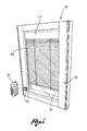
- figure 1 shows an overall view of a Venetian blind and of a relevant control device according to the present invention
- figure 2 shows a perspective view of a Venetian blind without a glass locking frame
- figure 3 shows a view of a portion of a Venetian blind in a second embodiment thereof, wherein the actuating device is shown excessively enlarged;
- figure 4 shows a cutaway view of a Venetian blind at the level of the electro-motor apparatus
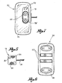
- figure 5 shows the contact holder plate of the actuating system
- figure 6 shows the back side of the control device
- figure 7 shows the front side of the control device
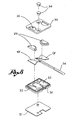
- figure 8 shows a perspective exploded view of the contact holder plate
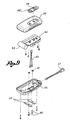
- figure 9 shows a perspective exploded view of the control device.
- the actuating system for actuating a Venetian blind 10 of the present invention is advantageously applicable to a Venetian blind 10 with double glazing, that is, a blind 10 wherein the adjustable blades 12 and the relevant moving means are arranged in a sealed air space delimited by two glasses 10'.
- the invention in any case is applicable in the same way to other types of doors or windows, such as roller shutters, provided with a motor driven apparatus for moving the closing means of such doors or windows.
- the system for actuating the Venetian blind 10 comprises an electro-motor apparatus 11 ( Figure 4 ) suitable for moving in an automated manner the rise and the lowering of blades 12 of said Venetian blind 10.
- the electro-motor apparatus 11 is seated in portion of a frame 13 supporting blind 10.
- the electro-motor apparatus 11 comprises a motor-reduction gear 14 coupled to a roller or shaft 15 for winding/unwinding ropes 12' for moving blades 12.
- Motor-reduction gear 14 and shaft 15 are located in a seat 16 with horizontal extension obtained in a box or a top portion 17 of frame 13 of the blind 10.
- shaft 15 is associated to a mechanical stop device 18 suitable for stopping the movement of said shaft 15 when the blind 10 reaches a predetermined height position.
- Seat 16 has no further electrical or electronic device for supplying 22 and controlling 20 the electro-motor apparatus 11.
- a contact holder plate 19 is fixed to frame 13 of blind 10, or to one of glasses 10', in any case in a position comfortably accessible by a user, wherein at least two electrical contacts 19' electrically connected to the motor-reduction gear 14 are buried.
- the contact holder plate 19 is suitable for electrically coupling to a control device 20 comprising electrical supply means 22 of the motor-reduction gear 14 and electronic control means 44 of said gear 14.
- the control device 20 is shaped as a usual remote control, that is, it is a device included in a box shaped container 26 separate from blind 10 and that can be carried by a user.
- the control device 20 is provided with electrical contacts 23 suitable for electrically coupling to the electrical contacts 19' of plate 19 for electrically connecting the supply means 22 and the electronic control means 44 to the electro-motor apparatus 11.
- the contact holder plate 19 is glued to glass 10' ( Figures 3 , 4 ), screwed to frame 13 ( Figure 1 ) or to a simple glass locking frame 50 removably coupled to the frame 13 ( figure 2 ), according to the needs.
- Plate 19 is connected to the motor-reduction gear 14 by electrical conductors 24, for example shaped as a plate, which extends along an external element 25 of the blind frame 13 and which can advantageously be hidden by the glass locking frame 50, so as to be substantially hidden to sight.
- the electrical conductors 24. are associated to sealing means suitable for preventing any air passage between the inside of the air space and the external environment.
- the contact holder plate 19 and the control device 20 can be magnetically coupled to each other so as to obtain the electrical connection between the respective electrical contacts 19', 23.
- the matching between plate 19 and control device 20 that allows establishing an electrical connection between the respective electrical contacts 19', 23 is given by a magnetic field that attracts the control device 20 to the plate 19.
- the contact holder plate 19 is provided with a magnet 29 suitable for attracting an element made of a ferromagnetic material 23 associated to the control device 20.
- the contact holder plate 19 is provided with two magnets 29 suitable for coupling with corresponding plates of ferromagnetic material associated to the control device 20 and acting as electrical contacts 23.
- each electrical contact 19' of plate 19 is placed in contact with a respective magnet 29 so as to make a single conductor element therewith.
- magnets 29 have the dual function of coupling means between the control device 20 and plate 19 and electrical conduction means between contacts 23 of the control device 20 and contacts 19' of plate 19. It should be noted that the presence of the electrical contacts 19' is suitable because it would be complicated to connect, for example by welding, the electrical conductors 24 directly to magnets 29.
- the magnetic coupling is such as to overcome the weight force of the control device 20, which remains fixed to plate 19 as soon as it is moved near it, without the need of being manually supported by the user and without the use of further coupling means.
- the ferromagnetic material of electrical contacts 23 for example is ferric phosphate.
- the contact holder plate 19 comprises a base 30 suitable for being fixed, for example by a two-faced sheet 31, to the glass 10' or to the frame 13 of the door or window. Two seats 32 are obtained in said base 30, in each there is seated an electrical contact 19' and a magnet 29 superimposed thereto.
- the electrical contacts 19' exhibit a laminar shape and are welded to conductors 24 that protrude from plate 19. Magnets 29 also exhibit a flat shape as a tablet.
- Plate 19 is completed by a cover 33 fixed to base 30, for example by screws 34. At the level of magnets 29, the cover 33 has respective windows 35 wherethrough the outer surface of magnets 29 protrudes, suitable for contacting plates 23 of the control device 20.
- Plate 19 therefore has a very small thickness, for example in the range of few millimetres. Magnets 29 are almost buried in plate 19, that is, they do not considerably protrude from the front surface of the plate 19 itself.
- Base 30 and cover 33 of plate 19 may also be made of plastic material or rubber, for example transparent polycarbonate, so as to hide as much as possible with the frame 13 or the glass 10'.
- plates 23 of the control device 20 have a flat shape so as to not considerably protrude from the box shaped container 26 of the control device 20.
- plates 23 have a contact surface sufficiently wide to allow the immediate centring and thus locking between control device 20 and plate 19.
- the user needs not be careful to the alignment between magnets 29 of plate 19 and plates 23 of the control device 20; instead, as the user approaches the control device 20 to plate 19, so that the side of the box shaped container 26 carrying plates 23 faces plate 19, the magnetic field force makes the two parts conjugate immediately in a correct manner.
- plates 23 are fixed to the box shaped container 26 of the control device 20 by contact screws 40.
- the contact screws 40 penetrate in said box shaped container 26 and are electrically connected to the power 22 and control means 44 of the motor apparatus 11.
- said screws 40 are screwed to locking washers 41 that fasten the screws 40 themselves to a pair of electrical cables 42 that connect the electrical contacts 23, 40 to the supply 22 and control means 44 of the motor apparatus 11 provided into the box shaped container 26.
- the power supply means 22 comprise at least one electrical battery, preferably of the rechargeable type.
- the control device 20 is provided with an electrical plug 27 for the connection to a battery charger (not shown).
- the electronic control means 44 comprise:
- the means with self-learning function allow storing a travel end position subsequent to the detection of a current peak due to the activation of the mechanical stop device 18.
- the circuit for detecting the current absorbed is provided for interrupting the supply to the electro-motor apparatus 11 when the absorbed current exceeds a predetermined threshold value.
- control device 20 comprises at least one electrical switch actuable by a user by a key 28, 28' or a button for activating/deactivating an electrical connection between the power supply means 22 and/or the electronic control means 44 of the control device 20 and the electro-motor gear 14.
- a key 28 may be provided for controlling the rise of blind 10 and a key 28' for controlling the lowering of the blind 10.
- the control device 20 is further provided with light signalling devices 52 for indicating, for example, the correct movement of the blind 10 rising or lowering, or the status of battery.
- the actuating system with magnetic coupling allows a user to press a blind rise 28 or lowering 28' key and thanks to the fact that the control device 20 remains autonomously connected to the contact holder plate 19, leaving the control device 20 while the blind 10 is moved, for example for controlling other blinds 10.
- control device 20 can be disconnected from plate 19, but can also remain connected thereto.
Landscapes
- Engineering & Computer Science (AREA)
- Structural Engineering (AREA)
- Architecture (AREA)
- Civil Engineering (AREA)
- Operating, Guiding And Securing Of Roll- Type Closing Members (AREA)
- Blinds (AREA)
- Power-Operated Mechanisms For Wings (AREA)
Claims (22)
- Système pour actionner un store vénitien (10), un store plissé, un store rideau, un volet roulant ou d'autres moyens similaires pour fermer une porte ou une fenêtre, comprenant :- un appareil à moteur électrique (11) approprié pour déplacer ledit store vénitien (10), volet ou analogue, ledit appareil (11) étant approprié pour être placé dans un siège (16) formé dans un corps ou une partie d'un châssis (13) de ladite porte ou fenêtre, ledit siège (16) étant exempt de tout dispositif d'alimentation et de commande électrique ou électronique (22, 20),- une plaque porte-contact (19) appropriée pour être fixée au verre (10') de la porte ou de la fenêtre dans une position accessible à un utilisateur et comprenant au moins deux contacts électriques (19') connectés électriquement audit appareil à moteur électrique (11), et- un dispositif de commande (20) comprenant des moyens d'alimentation électriques (22) de l'appareil à moteur électrique (11) et des moyens de commande électroniques (44) pour commander ledit appareil (11), ledit dispositif de commande (20) pouvant être transporté par un utilisateur et ayant au moins deux contacts électriques (23) appropriés pour un couplage avec les contacts électriques (19') de la plaque porte-contact (19) afin de connecter électriquement lesdits moyens d'alimentation (22) et lesdits moyens électroniques (44) pour commander l'appareil à moteur électrique (11),caractérisé en ce que la plaque porte-contact (19) est munie de deux aimants (29), chaque contact électrique (19') de la plaque porte-contact (19) étant placé en contact avec un aimant respectif (29) afin de former un seul élément conducteur avec celui-ci et en ce que le dispositif de commande (20) comprend deux éléments (23) fabriqués en matériau ferromagnétique appropriés pour être attirés par lesdits aimants (29) et agissant comme les contacts électriques (23), de sorte que la plaque porte-contact (19) et le dispositif de commande (20) soient appropriés pour être couplés magnétiquement l'un avec l'autre afin d'obtenir la connexion électrique entre les contacts électriques respectifs (19', 23).
- Système selon la revendication 1, dans lequel la plaque porte-contact (19) comprend une base (30) appropriée pour être fixée sur le verre (10') ou sur le châssis de la porte ou de la fenêtre (13), dans laquelle on obtient deux sièges (32) dans chacun desquels est logé un contact électrique (19') avec un aimant (29) qui lui est superposé.
- Système selon la revendication 2, dans lequel les contacts électriques (19') ont une forme laminaire et sont soudés à des câbles conducteurs respectifs (24) faisant saillie de la plaque (19).
- Système selon la revendication 3, dans lequel les aimants (29) ont également une forme aplatie comme un comprimé de manière à être sensiblement noyés dans la base (30) de la plaque porte-contact (19).
- Système selon la revendication 4, dans lequel la plaque porte-contact (19) est fermée par un couvercle (33), dans lequel il se présente au niveau des aimants (29) des fenêtres respectives (35) à travers lesquelles la surface externe des aimants (29) fait saillie, ce qui s'avère approprié pour la mettre en contact avec les plaques (23) du dispositif de commande (20).
- Système selon l'une quelconque des revendications précédentes, dans lequel le couplage magnétique entre la plaque porte-contact (19) et le dispositif de commande (20) est conçu pour pallier la force pondérale dudit dispositif de commande (20).
- Système selon l'une quelconque des revendications précédentes, dans lequel la plaque porte-contact (19) est fabriquée en matériau plastique ou en caoutchouc, par exemple en polycarbonate transparent.
- Système selon l'une quelconque des revendications précédentes, dans lequel les contacts électriques (23) du dispositif de commande (20) sont fixés à un récipient en forme de boîte (26) du dispositif de commande (20) par des vis de contact (40) qui pénètrent dans ledit récipient (26) et sont connectés électriquement aux moyens d'alimentation électrique (22) et de commande (44) du dispositif de commande (20).
- Système selon l'une quelconque des revendications précédentes, dans lequel ledit appareil à moteur électrique (11) comprend un moteur à engrenage réducteur (14).
- Système selon la revendication 9, dans lequel ledit moteur à engrenage réducteur (14) est couplé à un rouleau ou à un arbre (15) pour enrouler/dérouler le store vénitien (10), le volet roulant ou analogue.
- Système selon l'une quelconque des revendications précédentes, dans lequel lesdits moyens d'alimentation électrique (22) comprennent au moins une batterie électrique, par exemple du type rechargeable.
- Système selon l'une quelconque des revendications précédentes, dans lequel le dispositif de commande (20) comprend au moins un commutateur électrique pouvant être actionné par un utilisateur à l'aide d'une touche ou d'un bouton (28, 28') pour activer/désactiver une connexion électrique entre les moyens d'alimentation électriques (22) et/ou les moyens de commande électroniques (44) du dispositif de commande (2 0 ) et 1 ' appareil à moteur électrique (11).
- Système selon l'une quelconque des revendications précédentes, dans lequel lesdits moyens de commande électroniques (44) comprennent des moyens pour assurer un mouvement dans un sens et dans le sens opposé du store (10), du volet roulant ou analogue, permettant son arrêt dans n'importe quelle position.
- Système selon l'une quelconque des revendications précédentes, dans lequel lesdits moyens de commande électroniques (44) comprennent des moyens pour commander un mouvement lent du store vénitien (10), du volet roulant ou analogue, permettant la rotation et l'ajustement de la lumière.
- Système selon l'une quelconque des revendications précédentes, dans lequel lesdits moyens de commande électroniques (44) comprennent au moins un circuit pour acquérir la position et la vitesse de l'appareil à moteur électrique (11) et un circuit pour détecter le courant absorbé par ledit appareil (11).
- Système selon la revendication 15, dans lequel ledit circuit pour détecter le courant absorbé est fourni pour interrompre l'alimentation de l'appareil à moteur électrique (11) lorsque le courant absorbé dépasse une valeur de seuil prédéterminée.
- Système selon la revendication 10, dans lequel l'arbre ou le rouleau (15) couplé à l'appareil à moteur électrique (11) est associé à un dispositif d'arrêt mécanique (18) approprié pour arrêter le mouvement dudit arbre (15) lorsque le store (10), le volet roulant ou analogue atteint une position prédéterminée.
- Système selon la revendication 17, dans lequel lesdits moyens de commande électroniques (44) comprennent des moyens avec une fonction d'auto-apprentissage permettant d'enregistrer une position de fin de déplacement à la suite de la détection d'un pic de courant dû à l'activation du dispositif d'arrêt mécanique (18).
- Système selon l'une quelconque des revendications précédentes, dans lequel lesdits moyens de commande électroniques (44) comprennent des moyens pour l'étalonnage du courant absorbé par l'appareil à moteur électrique (11) en se basant sur le poids et les dimensions du store vénitien (10), du volet roulant ou analogue.
- Porte ou fenêtre ayant un store vénitien (10), un volet roulant ou un moyen mobile similaire, tel qu'un moyen de fermeture, comprenant un système selon l'une quelconque des revendications précédentes pour actionner le store vénitien (10), le volet roulant ou un moyen mobile similaire, dans laquelle l'appareil à moteur électrique (11) est placé dans un siège (16) formé dans un corps ou une partie d'un châssis (13) de ladite porte ou fenêtre, ledit siège (16) étant exempt de tout dispositif d'alimentation et de commande électrique ou électronique (22, 20) à l'intérieur dudit corps ou de ladite partie de châssis, et dans laquelle la plaque porte-contact (19) est fixée au verre (10') ou au châssis (13) de la porte ou de la fenêtre ou à un châssis de verrouillage de verre (50) de la porte ou de la fenêtre, dans une position accessible à un utilisateur.
- Porte ou fenêtre selon la revendication 20, dans laquelle la plaque porte-contact (19) est collée au verre (10') ou vissée sur le châssis (13) ou sur le châssis de verrouillage de verre (50) couplé de manière amovible au châssis (13).
- Porte ou fenêtre selon la revendication 20 ou 21, dans laquelle la plaque porte-contact (19) est connectée à l'appareil à moteur électrique (11) par des conducteurs électriques (24), s'étendant le long d'un élément externe (25) du châssis de porte ou de fenêtre (13) et cachés par le châssis de verrouillage de verre (50) de manière à être entièrement dérobé au regard.
Priority Applications (2)
| Application Number | Priority Date | Filing Date | Title |
|---|---|---|---|
| SI200730362T SI1936103T1 (sl) | 2006-12-13 | 2007-12-06 | Sistem za proženje rolete s prenosno krmilno enoto ki vsebuje vir električnega napajanja |
| PL07122510T PL1936103T3 (pl) | 2006-12-13 | 2007-12-06 | Układ do uruchamiania żaluzji rolkowej z przenośnym urządzeniem sterującym zawierający zasilanie energią elektryczną |
Applications Claiming Priority (1)
| Application Number | Priority Date | Filing Date | Title |
|---|---|---|---|
| IT000219A ITBS20060219A1 (it) | 2006-12-13 | 2006-12-13 | Sistema di attuazione di una tenda alla veneziana, di una persiana avvolgibile o di altri mezzi movibili di chiusura di una porta o finestra |
Publications (3)
| Publication Number | Publication Date |
|---|---|
| EP1936103A2 EP1936103A2 (fr) | 2008-06-25 |
| EP1936103A3 EP1936103A3 (fr) | 2009-02-18 |
| EP1936103B1 true EP1936103B1 (fr) | 2010-07-21 |
Family
ID=39185903
Family Applications (1)
| Application Number | Title | Priority Date | Filing Date |
|---|---|---|---|
| EP07122510A Active EP1936103B1 (fr) | 2006-12-13 | 2007-12-06 | Système pour l'actionnement d'un volet roulant avec une unité de commande portable comportant une source d'alimentation électrique |
Country Status (8)
| Country | Link |
|---|---|
| EP (1) | EP1936103B1 (fr) |
| AT (1) | ATE474993T1 (fr) |
| DE (1) | DE602007007878D1 (fr) |
| ES (1) | ES2348796T3 (fr) |
| IT (1) | ITBS20060219A1 (fr) |
| PL (1) | PL1936103T3 (fr) |
| PT (1) | PT1936103E (fr) |
| SI (1) | SI1936103T1 (fr) |
Cited By (3)
| Publication number | Priority date | Publication date | Assignee | Title |
|---|---|---|---|---|
| US9241590B2 (en) | 2013-11-18 | 2016-01-26 | Gordon's Window Decor, Inc. | Quick-release control system for architectural opening covering |
| US11462871B2 (en) | 2019-10-22 | 2022-10-04 | Hunter Douglas Inc. | Power supply box for use with an architectural-structure covering |
| US12503910B2 (en) | 2019-09-06 | 2025-12-23 | Pellini S.P.A. | Insulated glazing units with memory modules |
Families Citing this family (6)
| Publication number | Priority date | Publication date | Assignee | Title |
|---|---|---|---|---|
| AU2013100229B4 (en) * | 2009-01-13 | 2013-07-04 | Automatic Technology (Australia) Pty Ltd | Door Operator Unit Having a Motor Unit Housing and an Electric Component Housing |
| AU2009100360B4 (en) * | 2009-01-13 | 2009-09-10 | Automatic Technology (Australia) Pty Ltd | Door Operator Unit Having a Motor Unit Housing and an Electric Component Housing |
| US20130276995A1 (en) * | 2012-04-18 | 2013-10-24 | Homerun Holdings Corporation | Counterbalanced roll type blind or shade system having a configuration to utilize an external power supply or an external motor controller |
| GR1007939B (el) * | 2012-08-24 | 2013-07-16 | Στυλιανος Αθανασιου Κουπουρτιδης | Μηχανισμος κινησης περσιδων με μαγνητη τοποθετημενων εσωτερικα στο διακενο διπλου υαλοπινακα με τη χρηση μικρου ηλεκτροκινητηρα συνεχους ρευματος |
| WO2018200978A2 (fr) | 2017-04-28 | 2018-11-01 | Lutron Electronics Co., Inc. | Support de montage de traitement de fenêtre |
| IT202300013998A1 (it) * | 2023-07-05 | 2025-01-05 | Sun Bell S R L | Sistema di attuazione per una tenda mobile motorizzata |
Family Cites Families (8)
| Publication number | Priority date | Publication date | Assignee | Title |
|---|---|---|---|---|
| US3810258A (en) * | 1972-07-11 | 1974-05-07 | W Mathauser | Quick connect electrical coupler |
| DE4008939A1 (de) * | 1990-03-20 | 1991-09-26 | Elero Antrieb Sonnenschutz | Elektronische rolladensteuerung mit steckbarem steuerteil |
| WO2002064938A1 (fr) * | 2001-02-15 | 2002-08-22 | Alfred Schellenberg Gmbh | Dispositif et procede de commande d'une sangle de volet roulant |
| FR2826517B1 (fr) * | 2001-06-20 | 2004-03-12 | Somfy | Dispositif d'alimentation pour store motorise ou similaire |
| AUPS224902A0 (en) * | 2002-05-13 | 2002-06-13 | Ozroll Ip Pty Ltd | A shutter assembly |
| CN2637690Y (zh) * | 2003-07-25 | 2004-09-01 | 亿丰综合工业股份有限公司 | 易于更换电池的电动窗帘 |
| US7026789B2 (en) * | 2003-12-23 | 2006-04-11 | Motorola, Inc. | Charging system for electronic devices |
| KR200373326Y1 (ko) * | 2004-10-12 | 2005-01-27 | 주식회사 한스 | 원격 제어 가능한 자동 블라인드 내장형 복층 유리 창호 |
-
2006
- 2006-12-13 IT IT000219A patent/ITBS20060219A1/it unknown
-
2007
- 2007-12-06 AT AT07122510T patent/ATE474993T1/de not_active IP Right Cessation
- 2007-12-06 ES ES07122510T patent/ES2348796T3/es active Active
- 2007-12-06 SI SI200730362T patent/SI1936103T1/sl unknown
- 2007-12-06 EP EP07122510A patent/EP1936103B1/fr active Active
- 2007-12-06 DE DE602007007878T patent/DE602007007878D1/de active Active
- 2007-12-06 PL PL07122510T patent/PL1936103T3/pl unknown
- 2007-12-06 PT PT07122510T patent/PT1936103E/pt unknown
Cited By (4)
| Publication number | Priority date | Publication date | Assignee | Title |
|---|---|---|---|---|
| US9241590B2 (en) | 2013-11-18 | 2016-01-26 | Gordon's Window Decor, Inc. | Quick-release control system for architectural opening covering |
| US10030443B2 (en) | 2013-11-18 | 2018-07-24 | Gordon's Window Decor, Inc. | Quick-release control system for architectural opening covering |
| US12503910B2 (en) | 2019-09-06 | 2025-12-23 | Pellini S.P.A. | Insulated glazing units with memory modules |
| US11462871B2 (en) | 2019-10-22 | 2022-10-04 | Hunter Douglas Inc. | Power supply box for use with an architectural-structure covering |
Also Published As
| Publication number | Publication date |
|---|---|
| ITBS20060219A1 (it) | 2008-06-14 |
| EP1936103A2 (fr) | 2008-06-25 |
| PT1936103E (pt) | 2010-10-21 |
| SI1936103T1 (sl) | 2010-11-30 |
| PL1936103T3 (pl) | 2010-12-31 |
| EP1936103A3 (fr) | 2009-02-18 |
| DE602007007878D1 (de) | 2010-09-02 |
| ES2348796T3 (es) | 2010-12-14 |
| ATE474993T1 (de) | 2010-08-15 |
Similar Documents
| Publication | Publication Date | Title |
|---|---|---|
| EP1936103B1 (fr) | Système pour l'actionnement d'un volet roulant avec une unité de commande portable comportant une source d'alimentation électrique | |
| US12065876B2 (en) | Motorized window treatment | |
| CN100504016C (zh) | 控制可移动障碍物操作的方法 | |
| EP2010745B1 (fr) | Mécanisme à ressort permettant de soulever et d'abaisser une charge | |
| US9959997B2 (en) | Remote controlled switch cover | |
| CN101715313A (zh) | 用于马桶的自动座圈和/或盖板组件 | |
| US8561348B2 (en) | Security automatic garage door closer | |
| CA2590862A1 (fr) | Commande automatique de store | |
| US20230009409A1 (en) | Electromechanical actuator for blackout or sun-shading device and blackout or sun-shading installation comprising such an actuator | |
| CN105144326A (zh) | 远程可控开关操作设备 | |
| CN114901108B (zh) | 机动驱动装置、掩蔽或日光保护装置及家庭自动化设备 | |
| CN115735045A (zh) | 包括电动设备的遮蔽设备 | |
| KR100706328B1 (ko) | 슬라이드 도어의 전동 개폐장치 | |
| US20070144684A1 (en) | Door glass assembly with powered blind | |
| EP0878600A3 (fr) | Dispositif d'ouverture basculante pour portes ou fenêtres actionné par un moteur électrique | |
| CN103997830B (zh) | 开关设备及其控制方法 | |
| CN110259315B (zh) | 门锁用电机驱动机构 | |
| ES2246193T1 (es) | Dispositivo de alimentacion electrica de una cerradura motorizada. | |
| CN118390929A (zh) | 浴室调光玻璃门及调光方法 | |
| EP3400604B1 (fr) | Couvercle d'interrupteur télécommandé | |
| CN210659668U (zh) | 门锁用电机驱动机构 | |
| CN110206471A (zh) | 可自动调节的人工智能百叶窗帘 | |
| JP4268600B2 (ja) | 引戸開閉装置 | |
| EP4653658A1 (fr) | Système de motorisation intégré pour actionner les lamelles orientables des volets battants | |
| JP3087940U (ja) | 警報装置 |
Legal Events
| Date | Code | Title | Description |
|---|---|---|---|
| PUAI | Public reference made under article 153(3) epc to a published international application that has entered the european phase |
Free format text: ORIGINAL CODE: 0009012 |
|
| AK | Designated contracting states |
Kind code of ref document: A2 Designated state(s): AT BE BG CH CY CZ DE DK EE ES FI FR GB GR HU IE IS IT LI LT LU LV MC MT NL PL PT RO SE SI SK TR |
|
| AX | Request for extension of the european patent |
Extension state: AL BA HR MK RS |
|
| PUAL | Search report despatched |
Free format text: ORIGINAL CODE: 0009013 |
|
| AK | Designated contracting states |
Kind code of ref document: A3 Designated state(s): AT BE BG CH CY CZ DE DK EE ES FI FR GB GR HU IE IS IT LI LT LU LV MC MT NL PL PT RO SE SI SK TR |
|
| AX | Request for extension of the european patent |
Extension state: AL BA HR MK RS |
|
| 17P | Request for examination filed |
Effective date: 20090814 |
|
| 17Q | First examination report despatched |
Effective date: 20090909 |
|
| AKX | Designation fees paid |
Designated state(s): AT BE BG CH CY CZ DE DK EE ES FI FR GB GR HU IE IS IT LI LT LU LV MC MT NL PL PT RO SE SI SK TR |
|
| GRAP | Despatch of communication of intention to grant a patent |
Free format text: ORIGINAL CODE: EPIDOSNIGR1 |
|
| RTI1 | Title (correction) |
Free format text: SYSTEM FOR ACTUATING A ROLLER SHUTTER WITH A PORTABLE CONTROL DEVICE CONTAINING THE ELECTRIC ENERGY SUPPLY |
|
| GRAS | Grant fee paid |
Free format text: ORIGINAL CODE: EPIDOSNIGR3 |
|
| GRAA | (expected) grant |
Free format text: ORIGINAL CODE: 0009210 |
|
| AK | Designated contracting states |
Kind code of ref document: B1 Designated state(s): AT BE BG CH CY CZ DE DK EE ES FI FR GB GR HU IE IS IT LI LT LU LV MC MT NL PL PT RO SE SI SK TR |
|
| REG | Reference to a national code |
Ref country code: GB Ref legal event code: FG4D |
|
| REG | Reference to a national code |
Ref country code: CH Ref legal event code: EP |
|
| REG | Reference to a national code |
Ref country code: IE Ref legal event code: FG4D |
|
| REF | Corresponds to: |
Ref document number: 602007007878 Country of ref document: DE Date of ref document: 20100902 Kind code of ref document: P |
|
| REG | Reference to a national code |
Ref country code: GR Ref legal event code: EP Ref document number: 20100402020 Country of ref document: GR |
|
| REG | Reference to a national code |
Ref country code: RO Ref legal event code: EPE |
|
| REG | Reference to a national code |
Ref country code: NL Ref legal event code: T3 |
|
| REG | Reference to a national code |
Ref country code: ES Ref legal event code: FG2A Effective date: 20101130 |
|
| LTIE | Lt: invalidation of european patent or patent extension |
Effective date: 20100721 |
|
| REG | Reference to a national code |
Ref country code: PL Ref legal event code: T3 |
|
| PG25 | Lapsed in a contracting state [announced via postgrant information from national office to epo] |
Ref country code: LT Free format text: LAPSE BECAUSE OF FAILURE TO SUBMIT A TRANSLATION OF THE DESCRIPTION OR TO PAY THE FEE WITHIN THE PRESCRIBED TIME-LIMIT Effective date: 20100721 Ref country code: AT Free format text: LAPSE BECAUSE OF FAILURE TO SUBMIT A TRANSLATION OF THE DESCRIPTION OR TO PAY THE FEE WITHIN THE PRESCRIBED TIME-LIMIT Effective date: 20100721 Ref country code: FI Free format text: LAPSE BECAUSE OF FAILURE TO SUBMIT A TRANSLATION OF THE DESCRIPTION OR TO PAY THE FEE WITHIN THE PRESCRIBED TIME-LIMIT Effective date: 20100721 |
|
| PG25 | Lapsed in a contracting state [announced via postgrant information from national office to epo] |
Ref country code: IS Free format text: LAPSE BECAUSE OF FAILURE TO SUBMIT A TRANSLATION OF THE DESCRIPTION OR TO PAY THE FEE WITHIN THE PRESCRIBED TIME-LIMIT Effective date: 20101121 Ref country code: CY Free format text: LAPSE BECAUSE OF FAILURE TO SUBMIT A TRANSLATION OF THE DESCRIPTION OR TO PAY THE FEE WITHIN THE PRESCRIBED TIME-LIMIT Effective date: 20100721 |
|
| REG | Reference to a national code |
Ref country code: HU Ref legal event code: AG4A Ref document number: E009037 Country of ref document: HU |
|
| REG | Reference to a national code |
Ref country code: SK Ref legal event code: T3 Ref document number: E 8344 Country of ref document: SK |
|
| PG25 | Lapsed in a contracting state [announced via postgrant information from national office to epo] |
Ref country code: BE Free format text: LAPSE BECAUSE OF FAILURE TO SUBMIT A TRANSLATION OF THE DESCRIPTION OR TO PAY THE FEE WITHIN THE PRESCRIBED TIME-LIMIT Effective date: 20100721 Ref country code: LV Free format text: LAPSE BECAUSE OF FAILURE TO SUBMIT A TRANSLATION OF THE DESCRIPTION OR TO PAY THE FEE WITHIN THE PRESCRIBED TIME-LIMIT Effective date: 20100721 Ref country code: SE Free format text: LAPSE BECAUSE OF FAILURE TO SUBMIT A TRANSLATION OF THE DESCRIPTION OR TO PAY THE FEE WITHIN THE PRESCRIBED TIME-LIMIT Effective date: 20100721 |
|
| PG25 | Lapsed in a contracting state [announced via postgrant information from national office to epo] |
Ref country code: DK Free format text: LAPSE BECAUSE OF FAILURE TO SUBMIT A TRANSLATION OF THE DESCRIPTION OR TO PAY THE FEE WITHIN THE PRESCRIBED TIME-LIMIT Effective date: 20100721 |
|
| PLBE | No opposition filed within time limit |
Free format text: ORIGINAL CODE: 0009261 |
|
| STAA | Information on the status of an ep patent application or granted ep patent |
Free format text: STATUS: NO OPPOSITION FILED WITHIN TIME LIMIT |
|
| PG25 | Lapsed in a contracting state [announced via postgrant information from national office to epo] |
Ref country code: EE Free format text: LAPSE BECAUSE OF FAILURE TO SUBMIT A TRANSLATION OF THE DESCRIPTION OR TO PAY THE FEE WITHIN THE PRESCRIBED TIME-LIMIT Effective date: 20100721 |
|
| 26N | No opposition filed |
Effective date: 20110426 |
|
| REG | Reference to a national code |
Ref country code: DE Ref legal event code: R097 Ref document number: 602007007878 Country of ref document: DE Effective date: 20110426 |
|
| PG25 | Lapsed in a contracting state [announced via postgrant information from national office to epo] |
Ref country code: IE Free format text: LAPSE BECAUSE OF NON-PAYMENT OF DUE FEES Effective date: 20101206 |
|
| PG25 | Lapsed in a contracting state [announced via postgrant information from national office to epo] |
Ref country code: IT Free format text: LAPSE BECAUSE OF NON-PAYMENT OF DUE FEES Effective date: 20101206 Ref country code: MT Free format text: LAPSE BECAUSE OF FAILURE TO SUBMIT A TRANSLATION OF THE DESCRIPTION OR TO PAY THE FEE WITHIN THE PRESCRIBED TIME-LIMIT Effective date: 20100721 |
|
| REG | Reference to a national code |
Ref country code: CH Ref legal event code: PL |
|
| PG25 | Lapsed in a contracting state [announced via postgrant information from national office to epo] |
Ref country code: LU Free format text: LAPSE BECAUSE OF NON-PAYMENT OF DUE FEES Effective date: 20101206 |
|
| PG25 | Lapsed in a contracting state [announced via postgrant information from national office to epo] |
Ref country code: CH Free format text: LAPSE BECAUSE OF NON-PAYMENT OF DUE FEES Effective date: 20111231 Ref country code: LI Free format text: LAPSE BECAUSE OF NON-PAYMENT OF DUE FEES Effective date: 20111231 |
|
| REG | Reference to a national code |
Ref country code: FR Ref legal event code: PLFP Year of fee payment: 9 |
|
| REG | Reference to a national code |
Ref country code: FR Ref legal event code: PLFP Year of fee payment: 10 |
|
| REG | Reference to a national code |
Ref country code: FR Ref legal event code: PLFP Year of fee payment: 11 |
|
| P01 | Opt-out of the competence of the unified patent court (upc) registered |
Effective date: 20230508 |
|
| PGFP | Annual fee paid to national office [announced via postgrant information from national office to epo] |
Ref country code: PT Payment date: 20251127 Year of fee payment: 19 |
|
| PGFP | Annual fee paid to national office [announced via postgrant information from national office to epo] |
Ref country code: GB Payment date: 20251219 Year of fee payment: 19 |
|
| PGFP | Annual fee paid to national office [announced via postgrant information from national office to epo] |
Ref country code: MC Payment date: 20251223 Year of fee payment: 19 |
|
| PGFP | Annual fee paid to national office [announced via postgrant information from national office to epo] |
Ref country code: IT Payment date: 20251007 Year of fee payment: 19 |
|
| PGFP | Annual fee paid to national office [announced via postgrant information from national office to epo] |
Ref country code: HU Payment date: 20251223 Year of fee payment: 19 Ref country code: NL Payment date: 20251222 Year of fee payment: 19 Ref country code: FR Payment date: 20251128 Year of fee payment: 19 |
|
| PGFP | Annual fee paid to national office [announced via postgrant information from national office to epo] |
Ref country code: TR Payment date: 20251130 Year of fee payment: 19 Ref country code: GR Payment date: 20251222 Year of fee payment: 19 |
|
| PGFP | Annual fee paid to national office [announced via postgrant information from national office to epo] |
Ref country code: CZ Payment date: 20251021 Year of fee payment: 19 |
|
| PGFP | Annual fee paid to national office [announced via postgrant information from national office to epo] |
Ref country code: BG Payment date: 20251021 Year of fee payment: 19 Ref country code: PL Payment date: 20251118 Year of fee payment: 19 |
|
| PGFP | Annual fee paid to national office [announced via postgrant information from national office to epo] |
Ref country code: SK Payment date: 20251203 Year of fee payment: 19 Ref country code: RO Payment date: 20251205 Year of fee payment: 19 |
|
| PGFP | Annual fee paid to national office [announced via postgrant information from national office to epo] |
Ref country code: SI Payment date: 20251127 Year of fee payment: 19 |
|
| PGFP | Annual fee paid to national office [announced via postgrant information from national office to epo] |
Ref country code: ES Payment date: 20260102 Year of fee payment: 19 |
|
| PGFP | Annual fee paid to national office [announced via postgrant information from national office to epo] |
Ref country code: DE Payment date: 20251222 Year of fee payment: 19 |