EP1936232A2 - Amortisseur de vibrations de torsions - Google Patents
Amortisseur de vibrations de torsions Download PDFInfo
- Publication number
- EP1936232A2 EP1936232A2 EP07022648A EP07022648A EP1936232A2 EP 1936232 A2 EP1936232 A2 EP 1936232A2 EP 07022648 A EP07022648 A EP 07022648A EP 07022648 A EP07022648 A EP 07022648A EP 1936232 A2 EP1936232 A2 EP 1936232A2
- Authority
- EP
- European Patent Office
- Prior art keywords
- vibration damper
- torsional vibration
- end pieces
- damper according
- compression spring
- Prior art date
- Legal status (The legal status is an assumption and is not a legal conclusion. Google has not performed a legal analysis and makes no representation as to the accuracy of the status listed.)
- Withdrawn
Links
Images




Classifications
-
- F—MECHANICAL ENGINEERING; LIGHTING; HEATING; WEAPONS; BLASTING
- F16—ENGINEERING ELEMENTS AND UNITS; GENERAL MEASURES FOR PRODUCING AND MAINTAINING EFFECTIVE FUNCTIONING OF MACHINES OR INSTALLATIONS; THERMAL INSULATION IN GENERAL
- F16F—SPRINGS; SHOCK-ABSORBERS; MEANS FOR DAMPING VIBRATION
- F16F15/00—Suppression of vibrations in systems; Means or arrangements for avoiding or reducing out-of-balance forces, e.g. due to motion
- F16F15/10—Suppression of vibrations in rotating systems by making use of members moving with the system
- F16F15/12—Suppression of vibrations in rotating systems by making use of members moving with the system using elastic members or friction-damping members, e.g. between a rotating shaft and a gyratory mass mounted thereon
- F16F15/121—Suppression of vibrations in rotating systems by making use of members moving with the system using elastic members or friction-damping members, e.g. between a rotating shaft and a gyratory mass mounted thereon using springs as elastic members, e.g. metallic springs
- F16F15/123—Wound springs
- F16F15/1232—Wound springs characterised by the spring mounting
- F16F15/1234—Additional guiding means for springs, e.g. for support along the body of springs that extend circumferentially over a significant length
-
- F—MECHANICAL ENGINEERING; LIGHTING; HEATING; WEAPONS; BLASTING
- F16—ENGINEERING ELEMENTS AND UNITS; GENERAL MEASURES FOR PRODUCING AND MAINTAINING EFFECTIVE FUNCTIONING OF MACHINES OR INSTALLATIONS; THERMAL INSULATION IN GENERAL
- F16F—SPRINGS; SHOCK-ABSORBERS; MEANS FOR DAMPING VIBRATION
- F16F1/00—Springs
- F16F1/02—Springs made of steel or other material having low internal friction; Wound, torsion, leaf, cup, ring or the like springs, the material of the spring not being relevant
- F16F1/04—Wound springs
- F16F1/12—Attachments or mountings
- F16F1/128—Attachments or mountings with motion-limiting means, e.g. with a full-length guide element or ball joint connections; with protective outer cover
-
- F—MECHANICAL ENGINEERING; LIGHTING; HEATING; WEAPONS; BLASTING
- F16—ENGINEERING ELEMENTS AND UNITS; GENERAL MEASURES FOR PRODUCING AND MAINTAINING EFFECTIVE FUNCTIONING OF MACHINES OR INSTALLATIONS; THERMAL INSULATION IN GENERAL
- F16F—SPRINGS; SHOCK-ABSORBERS; MEANS FOR DAMPING VIBRATION
- F16F15/00—Suppression of vibrations in systems; Means or arrangements for avoiding or reducing out-of-balance forces, e.g. due to motion
- F16F15/10—Suppression of vibrations in rotating systems by making use of members moving with the system
- F16F15/12—Suppression of vibrations in rotating systems by making use of members moving with the system using elastic members or friction-damping members, e.g. between a rotating shaft and a gyratory mass mounted thereon
- F16F15/121—Suppression of vibrations in rotating systems by making use of members moving with the system using elastic members or friction-damping members, e.g. between a rotating shaft and a gyratory mass mounted thereon using springs as elastic members, e.g. metallic springs
- F16F15/123—Wound springs
- F16F15/1232—Wound springs characterised by the spring mounting
- F16F15/12326—End-caps for springs
- F16F15/12333—End-caps for springs having internal abutment means
-
- F—MECHANICAL ENGINEERING; LIGHTING; HEATING; WEAPONS; BLASTING
- F16—ENGINEERING ELEMENTS AND UNITS; GENERAL MEASURES FOR PRODUCING AND MAINTAINING EFFECTIVE FUNCTIONING OF MACHINES OR INSTALLATIONS; THERMAL INSULATION IN GENERAL
- F16F—SPRINGS; SHOCK-ABSORBERS; MEANS FOR DAMPING VIBRATION
- F16F15/00—Suppression of vibrations in systems; Means or arrangements for avoiding or reducing out-of-balance forces, e.g. due to motion
- F16F15/10—Suppression of vibrations in rotating systems by making use of members moving with the system
- F16F15/12—Suppression of vibrations in rotating systems by making use of members moving with the system using elastic members or friction-damping members, e.g. between a rotating shaft and a gyratory mass mounted thereon
- F16F15/121—Suppression of vibrations in rotating systems by making use of members moving with the system using elastic members or friction-damping members, e.g. between a rotating shaft and a gyratory mass mounted thereon using springs as elastic members, e.g. metallic springs
- F16F15/123—Wound springs
- F16F15/1232—Wound springs characterised by the spring mounting
- F16F15/12346—Set of springs, e.g. springs within springs
Definitions
- the invention relates to a torsional vibration damper, in particular a split flywheel or a clutch disc, with an input part and an output part which against the resistance of at least one energy storage device and from a defined angle of rotation additionally against the resistance of at least one relative to the energy storage device floating stop spring device relative to the input part is rotatable ,
- JP 2000-205295 A JP 2000-205296 A and JP 2006-077884 A
- Various types of rubber or elastomeric spring are known, which are arranged floating in a steel outer spring means.
- the known torsional vibration damper have the disadvantage that they have a relatively low spring capacity.
- a strong set may occur.
- the object of the invention is to provide a torsional vibration damper according to the preamble of claim 1, which is simple in construction and inexpensive to produce.
- the torsional vibration damper according to the invention should have a main damper characteristic curve which rises sharply after reaching a maximum engine torque in order to cover a possibly occurring over torque.
- the object is in a torsional vibration damper, in particular a split flywheel or a clutch disc, with an input part and an output part against the resistance of at least one energy storage device and from a defined angle of rotation additionally against the resistance of at least one relative to the energy storage device floating stop spring device relative to the input part rotatable is achieved in that the stop spring device comprises two mutually coupled end pieces which are displaceable relative to each other and away from each other.
- the torsional vibration damper is also referred to as a torsional vibration damper.
- the inventive coupling of the two end pieces together makes it possible in a simple manner to arrange or clamp a spring device between the end pieces. As a result, a sufficient spring capacity can be provided in a simple manner.
- a preferred embodiment of the torsional vibration damper is characterized in that arranged between the end pieces of a compression spring device, in particular clamped, is.
- a compression spring device By the compression spring device, an undesirable setting of the spring action can be significantly reduced.
- a further preferred embodiment of the torsional vibration damper is characterized in that the compression spring device comprises at least one helical compression spring.
- the helical compression spring is preferably formed of spring steel.
- Another preferred embodiment of the torsional vibration damper is characterized in that the end pieces are coupled together by at least one snap connection.
- the snap connection simplifies the assembly of the stop spring device considerably.
- a further preferred embodiment of the torsional vibration damper is characterized in that each of the end pieces emanate at least two snap hooks, each having at least one guide recess for a positioning element, which is provided on a snap hook of the other end piece.
- the snap hooks and the guide recesses are designed so that they serve for guiding and / or centering the two end pieces relative to each other.
- a further preferred embodiment of the torsional vibration damper is characterized in that the end pieces essentially each have the shape of a circular cylinder. From the mutually facing end faces of the end pieces, the snap hooks extend toward each other in the axial direction.
- a further preferred embodiment of the torsional vibration damper is characterized in that the energy storage device comprises at least one helical compression spring.
- the helical compression spring is preferably formed of spring steel.
- a further preferred embodiment of the torsional vibration damper is characterized in that the outer diameter of the end pieces is slightly smaller than the inner diameter of the energy storage device, in particular the helical compression spring. The play allows movement of the end pieces relative to the energy storage device.
- a further preferred embodiment of the torsional vibration damper is characterized in that the outer diameter of the end pieces is slightly larger than the inner diameter of the energy storage device, in particular the helical compression spring. Due to the excess friction can be generated on the one hand. On the other hand, the oversize makes it possible to position the stopper spring device, for example during balancing.
- Another preferred embodiment of the torsional vibration damper is characterized in that the end pieces are made the same. This simplifies manufacture.
- a further preferred embodiment of the torsional vibration damper is characterized in that the end pieces are formed crowned at their end faces facing away from each other. Preferably, the end pieces are curved in a longitudinal section convexly outwards. As a result, the system is improved on driver elements of the torsional vibration damper.
- a further preferred embodiment of the torsional vibration damper is characterized in that the lateral surfaces of the end pieces are formed crowned.
- the end pieces are curved convexly on the lateral surfaces in longitudinal section to the outside. As a result, the end pieces can be better adapted to the deformation of the energy storage device.
- a further preferred embodiment of the torsional vibration damper is characterized in that the end pieces have recesses on their outer periphery. Some recesses serve to position the stop spring device, in particular during pre-assembly. These recesses are also referred to as positioning recesses. Other recesses serve to ensure wall thicknesses that are as constant as possible. This simplifies the production of the end pieces by injection molding.
- a further preferred embodiment of the torsional vibration damper is characterized in that the end pieces are formed from a preferably fiber-reinforced plastic material.
- the plastic material is preferably a thermoplastic material.
- the plastic material dry lubricants added.
- the plastic material can advantageously be made resiliently resilient.
- FIG. 1 shows a Cartesian coordinate diagram in which the torque M is shown in Newton meters over the twist angle alpha in degrees of a torsional vibration damper according to the invention in the form of a characteristic curve, which is also referred to as the main damper characteristic.
- the characteristic curve increases linearly from the origin of coordinates until a moment reaches M1 is that corresponds to the maximum engine torque.
- the associated twist angle is ⁇ 1.
- a torsional vibration damper is provided with which in a simple manner the in FIG. 1 represented characteristic can be realized.
- the known disadvantages of rubber / elastomer springs and previous steel spring variants are compensated.
- FIG. 2 is a section of a torsional vibration damper according to the invention, which is also referred to as a torsional vibration damper, shown in section.
- the torsional vibration damper comprises an input part 2, which is rotatable about an axis of rotation 3 relative to an output part 4.
- two opposite driver elements 5, 6 are formed, which are also referred to as driving lugs.
- the driving lugs 5, 6 protrude into a window 8, which is recessed in the output part 4.
- a substantially annular disk-shaped system area 7, 9 is provided in each case.
- an energy storage device 10 is clamped in the window 8 of the output part 4, which comprises an outer spring 11 and an inner spring 12.
- the outer spring 11 and the inner spring 12 are designed as helical compression springs.
- the inner spring 12 extends in the interior of the outer spring 11 but radially outside of the driver elements 5, 6.
- the inner spring 12 of the energy storage device 10 defines in its interior a substantially circular cylindrical interior, in which a stop spring device 20 is arranged.
- the stop spring device 20 comprises two end pieces 21, 22.
- the end piece 21 is arranged at a defined distance from the driver element 5.
- the associated angle of rotation about the axis of rotation 3 is designated by ax.
- the end piece 22 is arranged at a defined distance from the driver element 6.
- the associated twist angle is denoted by ⁇ y.
- the angle of rotation ⁇ 1 associated with the maximum engine torque M1 results from the sum of the angles of rotation ⁇ x and ⁇ y.
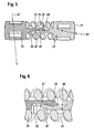
- the two end pieces 21, 22 are coupled together by a snap connection so that the two end pieces 21, 22 limited to each other and can move away from each other.
- a compression spring device 25 is arranged, preferably clamped. By the biasing force of the compression spring means 25, the two end pieces 21, 22 are held at a defined distance from each other.
- the end piece 22 comprises a substantially circular cylindrical base body 30 with a lateral surface 29 and two end faces 31, 32.
- a plurality of recesses 34, 35 are provided, which extend substantially parallelepiped in the base body 30.
- the recesses 34, 35 serve to ensure wall thicknesses that are as constant as possible and thus optimize the injection molding, without, however, reducing the rigidity too much.
- the main body 30 of the end piece 22 recesses 38, 39, which are formed by longitudinal grooves with a circular arc-shaped cross-section.
- the recesses 38, 39 serve to position the associated end piece 22 during pre-assembly.
- two snap hooks 41, 42 extend in relation to the base body 30, axial direction.
- the two snap hooks 41, 42 are integrally connected to the main body 30 via a common foot 43.
- the snap hook 41 has a guide recess 44 with a guide surface, which is arranged perpendicular to a guide surface of a guide recess 45 which is provided on the snap hook 42.
- a positioning element 47, 48 is provided at the free ends of the snap hooks 41, 42 in each case.
- the positioning elements 47, 48 are integrally connected to the common foot 43.
- the snap hooks 41, 42 with the guide recesses 44, 45 and the positioning elements 47, 48 are also referred to as a snap connection element 40.
- a snap connection element 50 is formed which is identical to the snap connection element 40 of the end piece 22.
- the snap connection element 50 comprises two snap hooks 51, 52 with guide recesses 54, 55 and positioning elements 57, 58.
- the positioning element 57 of the snap hook 51 engages in the guide recess 44 of the snap hook 41, that the two end pieces 21 can move in the axial direction relative to each other. The movement is limited by the length of the guide recess 44.
- the positioning element 47 of the snap-action hook 41 engages in the guide recess 55 of the snap-action hook 51.
- Radially outside the snap hooks 41, 51 abut against the compression spring device 25.
- the compression spring device 25 is designed as a helical compression spring.
- the outer diameter of the helical compression spring 25 corresponds approximately to the outer diameter of the main body of the end pieces 21 and 22.
- At the inner diameter of the helical compression spring 25 are the snap hooks 41, 51 at. This prevents unwanted release of the snap connection.
- the elasticity of the helical compression spring 25, the joining of the end pieces 21 and 22 allows.
- the lateral surface of the end piece 21 is crowned.
- the associated radius is designated 61.
- the end face 31 of the end piece 22 is also executed crowned.
- the associated radius is designated 62.
- the radii 61, 62 serve both the better contact with the driver elements of the torsional vibration damper and the better adaptation to the deformation of the steel compression spring assembly.
- the snap hooks additionally have a guiding function.
- the end piece 22 is shown alone in different views.
- the snap hooks 41, 42 are used both for centering and for clipping the end pieces.
- the end piece 22 is made of a fiber-reinforced and mixed with dry lubricants thermoplastic.
- the outer diameter of the main body 30 of the end piece 22 is designed so that a certain excess between the end piece 22 and the inner spring (12 in FIG. 1 ) of the energy storage device exists. This oversize can be used both for additional friction generation and for positioning for a balancing operation.
Landscapes
- Engineering & Computer Science (AREA)
- General Engineering & Computer Science (AREA)
- Mechanical Engineering (AREA)
- Physics & Mathematics (AREA)
- Acoustics & Sound (AREA)
- Aviation & Aerospace Engineering (AREA)
- Springs (AREA)
- Vibration Prevention Devices (AREA)
- Vibration Dampers (AREA)
- Mechanical Operated Clutches (AREA)
Applications Claiming Priority (1)
| Application Number | Priority Date | Filing Date | Title |
|---|---|---|---|
| DE102006059668 | 2006-12-18 |
Publications (2)
| Publication Number | Publication Date |
|---|---|
| EP1936232A2 true EP1936232A2 (fr) | 2008-06-25 |
| EP1936232A3 EP1936232A3 (fr) | 2009-07-08 |
Family
ID=39111511
Family Applications (1)
| Application Number | Title | Priority Date | Filing Date |
|---|---|---|---|
| EP07022648A Withdrawn EP1936232A3 (fr) | 2006-12-18 | 2007-11-22 | Amortisseur de vibrations de torsions |
Country Status (2)
| Country | Link |
|---|---|
| EP (1) | EP1936232A3 (fr) |
| CN (1) | CN101205959B (fr) |
Cited By (2)
| Publication number | Priority date | Publication date | Assignee | Title |
|---|---|---|---|---|
| WO2015057613A1 (fr) * | 2013-10-14 | 2015-04-23 | Fisher Controls International Llc | Ensemble siège de ressort à interverrouillage et vanne de commande rotative comprenant ledit ensemble |
| JP2018096448A (ja) * | 2016-12-13 | 2018-06-21 | アイシン精機株式会社 | ダンパ装置 |
Families Citing this family (6)
| Publication number | Priority date | Publication date | Assignee | Title |
|---|---|---|---|---|
| CN104755798B (zh) * | 2012-10-23 | 2017-05-17 | 舍弗勒技术股份两合公司 | 用于离合器盘的弹簧组 |
| FR3032019B1 (fr) * | 2015-01-26 | 2017-01-13 | Valeo Embrayages | Amortisseur de torsion a ressorts droits |
| JP6679359B2 (ja) * | 2016-03-18 | 2020-04-15 | 株式会社エクセディ | スプリング組立体、及びスプリング組立体を備えるダンパ装置。 |
| CN108953414B (zh) * | 2017-05-18 | 2021-11-16 | 舍弗勒技术股份两合公司 | 离合器从动盘及离合器 |
| CN113847359B (zh) * | 2021-12-01 | 2022-02-22 | 浙江铁流离合器股份有限公司 | 一种离合器从动盘扩充转角减振装置 |
| DE102022104006A1 (de) * | 2022-02-21 | 2023-08-24 | Schaeffler Technologies AG & Co. KG | Schwingungsdämpfer aufgebaut aus Speichenfedertilgern |
Citations (3)
| Publication number | Priority date | Publication date | Assignee | Title |
|---|---|---|---|---|
| JP2000205295A (ja) | 1999-01-19 | 2000-07-25 | Exedy Corp | ダンパ―ディスク組立体 |
| JP2000205296A (ja) | 1999-01-19 | 2000-07-25 | Exedy Corp | ダンパ―ディスク組立体 |
| JP2006077884A (ja) | 2004-09-09 | 2006-03-23 | Exedy Corp | スプリング組立体 |
Family Cites Families (5)
| Publication number | Priority date | Publication date | Assignee | Title |
|---|---|---|---|---|
| FR2371609A1 (fr) * | 1976-11-17 | 1978-06-16 | Ferodo Sa | Dispositif amortisseur de torsion notamment pour friction d'embrayage, en particulier de vehicule automobile |
| JPS60112727U (ja) * | 1984-01-05 | 1985-07-30 | 株式会社 大金製作所 | ダンパ−デイスク |
| DE4141723C2 (de) * | 1991-12-20 | 1999-12-16 | Mannesmann Sachs Ag | Torsionsschwingungsdämpfer mit Leerlauffederung |
| JP2004183870A (ja) * | 2002-12-06 | 2004-07-02 | Exedy Corp | スプリングシート、スプリング組立体 |
| JP4239627B2 (ja) * | 2003-03-18 | 2009-03-18 | アイシン精機株式会社 | 捩れ緩衝装置 |
-
2007
- 2007-11-22 EP EP07022648A patent/EP1936232A3/fr not_active Withdrawn
- 2007-12-18 CN CN2007101991779A patent/CN101205959B/zh not_active Expired - Fee Related
Patent Citations (3)
| Publication number | Priority date | Publication date | Assignee | Title |
|---|---|---|---|---|
| JP2000205295A (ja) | 1999-01-19 | 2000-07-25 | Exedy Corp | ダンパ―ディスク組立体 |
| JP2000205296A (ja) | 1999-01-19 | 2000-07-25 | Exedy Corp | ダンパ―ディスク組立体 |
| JP2006077884A (ja) | 2004-09-09 | 2006-03-23 | Exedy Corp | スプリング組立体 |
Cited By (4)
| Publication number | Priority date | Publication date | Assignee | Title |
|---|---|---|---|---|
| WO2015057613A1 (fr) * | 2013-10-14 | 2015-04-23 | Fisher Controls International Llc | Ensemble siège de ressort à interverrouillage et vanne de commande rotative comprenant ledit ensemble |
| CN104595505A (zh) * | 2013-10-14 | 2015-05-06 | 费希尔控制国际公司 | 互锁弹簧座组件和包括其的旋转控制阀 |
| JP2018096448A (ja) * | 2016-12-13 | 2018-06-21 | アイシン精機株式会社 | ダンパ装置 |
| WO2018109980A1 (fr) * | 2016-12-13 | 2018-06-21 | アイシン精機株式会社 | Appareil amortisseur |
Also Published As
| Publication number | Publication date |
|---|---|
| CN101205959B (zh) | 2012-03-21 |
| EP1936232A3 (fr) | 2009-07-08 |
| CN101205959A (zh) | 2008-06-25 |
Similar Documents
| Publication | Publication Date | Title |
|---|---|---|
| EP1936232A2 (fr) | Amortisseur de vibrations de torsions | |
| DE3125547C2 (de) | Mitnehmerscheibe für eine Kraftfahrzeug-Scheibenreibungskupplung | |
| DE10049001A1 (de) | Drehfedersatz | |
| EP1865222A1 (fr) | Dispositif de pendule à force centrifuge | |
| EP1233205A2 (fr) | Disposition de ressort | |
| EP2171302B1 (fr) | Accouplement de roue libre | |
| EP3377784B1 (fr) | Ensemble d'amortissement pour au moins une masse d'amortissement | |
| DE6607259U (de) | Torionsschwingungsdaempfer | |
| WO2007098745A1 (fr) | Ensemble roue dentée | |
| DE102016222247A1 (de) | Fliehkraftpendeleinrichtung | |
| EP0475283B1 (fr) | Disque d'embrayage | |
| DE102004060172B4 (de) | Kraftübertragungsvorrichtung | |
| DE2621787C2 (de) | Drehschwingungsgedämpfte Antriebswelle | |
| DE102018115589A1 (de) | Tellerfedermembran | |
| DE4229613C2 (de) | Stützlager | |
| DE3606063C3 (de) | Reibbelaggruppe | |
| DE3145054A1 (de) | Kupplungsgetriebene platteneinheit mit gedaempftem reibmaterial | |
| WO2008058500A2 (fr) | Disque d'embrayage | |
| DE102007056367A1 (de) | Drehschwingungsdämpfer | |
| DE102009016284B4 (de) | Befestigungsanordnung | |
| DE102010013632A1 (de) | Kupplungsscheibe | |
| DE102019206099B4 (de) | Vorrichtung zum Befestigen eines ersten Bauteils an einem zweiten Bauteil und zum Verpressen einer Dichtungsanordnung zwischen dem ersten Bauteil und einem dritten Bauteil | |
| DE1045183B (de) | Huelsenfoermige Gummimetallfeder mit nierenfoermigen Ausnehmungen fuer elastische Kupplungen | |
| DE102020127381A1 (de) | Freilaufnabe mit Feder aus Kunststoff mit zelliger Struktur | |
| DE10037299A1 (de) | Torsionsdämpfer für eine Kupplung, insbesondere für Kraftfahrzeuge |
Legal Events
| Date | Code | Title | Description |
|---|---|---|---|
| PUAI | Public reference made under article 153(3) epc to a published international application that has entered the european phase |
Free format text: ORIGINAL CODE: 0009012 |
|
| AK | Designated contracting states |
Kind code of ref document: A2 Designated state(s): AT BE BG CH CY CZ DE DK EE ES FI FR GB GR HU IE IS IT LI LT LU LV MC MT NL PL PT RO SE SI SK TR |
|
| AX | Request for extension of the european patent |
Extension state: AL BA HR MK RS |
|
| PUAL | Search report despatched |
Free format text: ORIGINAL CODE: 0009013 |
|
| AK | Designated contracting states |
Kind code of ref document: A3 Designated state(s): AT BE BG CH CY CZ DE DK EE ES FI FR GB GR HU IE IS IT LI LT LU LV MC MT NL PL PT RO SE SI SK TR |
|
| AX | Request for extension of the european patent |
Extension state: AL BA HR MK RS |
|
| AKX | Designation fees paid | ||
| STAA | Information on the status of an ep patent application or granted ep patent |
Free format text: STATUS: THE APPLICATION IS DEEMED TO BE WITHDRAWN |
|
| 18D | Application deemed to be withdrawn |
Effective date: 20100109 |
|
| REG | Reference to a national code |
Ref country code: DE Ref legal event code: 8566 Ref country code: DE Ref legal event code: R108 Effective date: 20100608 |
|
| P01 | Opt-out of the competence of the unified patent court (upc) registered |
Effective date: 20230523 |