EP1936266A2 - Dispositif de chauffage d'un liquide et machine à café - Google Patents
Dispositif de chauffage d'un liquide et machine à café Download PDFInfo
- Publication number
- EP1936266A2 EP1936266A2 EP07023012A EP07023012A EP1936266A2 EP 1936266 A2 EP1936266 A2 EP 1936266A2 EP 07023012 A EP07023012 A EP 07023012A EP 07023012 A EP07023012 A EP 07023012A EP 1936266 A2 EP1936266 A2 EP 1936266A2
- Authority
- EP
- European Patent Office
- Prior art keywords
- tube
- radiator
- contact surfaces
- radiators
- heating
- Prior art date
- Legal status (The legal status is an assumption and is not a legal conclusion. Google has not performed a legal analysis and makes no representation as to the accuracy of the status listed.)
- Withdrawn
Links
- 238000010438 heat treatment Methods 0.000 title claims abstract description 41
- 235000013353 coffee beverage Nutrition 0.000 title claims description 8
- 239000007788 liquid Substances 0.000 title claims description 6
- 229910052782 aluminium Inorganic materials 0.000 claims abstract description 11
- XAGFODPZIPBFFR-UHFFFAOYSA-N aluminium Chemical compound [Al] XAGFODPZIPBFFR-UHFFFAOYSA-N 0.000 claims abstract description 11
- 229910000838 Al alloy Inorganic materials 0.000 claims abstract description 8
- 239000004020 conductor Substances 0.000 claims abstract description 5
- XLYOFNOQVPJJNP-UHFFFAOYSA-N water Substances O XLYOFNOQVPJJNP-UHFFFAOYSA-N 0.000 claims description 12
- 235000008733 Citrus aurantifolia Nutrition 0.000 claims description 3
- 235000011941 Tilia x europaea Nutrition 0.000 claims description 3
- 239000011248 coating agent Substances 0.000 claims description 3
- 238000000576 coating method Methods 0.000 claims description 3
- 239000004571 lime Substances 0.000 claims description 3
- 239000004810 polytetrafluoroethylene Substances 0.000 claims description 2
- 229920001343 polytetrafluoroethylene Polymers 0.000 claims description 2
- 150000001875 compounds Chemical class 0.000 claims 1
- 230000017525 heat dissipation Effects 0.000 claims 1
- 229910000679 solder Inorganic materials 0.000 claims 1
- 235000015114 espresso Nutrition 0.000 description 3
- 239000000463 material Substances 0.000 description 3
- 239000010935 stainless steel Substances 0.000 description 3
- 229910001220 stainless steel Inorganic materials 0.000 description 3
- 238000009835 boiling Methods 0.000 description 2
- 238000013021 overheating Methods 0.000 description 2
- 244000089486 Phragmites australis subsp australis Species 0.000 description 1
- 229910000831 Steel Inorganic materials 0.000 description 1
- 238000011109 contamination Methods 0.000 description 1
- 238000004512 die casting Methods 0.000 description 1
- 230000002349 favourable effect Effects 0.000 description 1
- 239000011810 insulating material Substances 0.000 description 1
- 235000000396 iron Nutrition 0.000 description 1
- 238000004519 manufacturing process Methods 0.000 description 1
- 229910052751 metal Inorganic materials 0.000 description 1
- 239000002184 metal Substances 0.000 description 1
- 238000005192 partition Methods 0.000 description 1
- 230000002093 peripheral effect Effects 0.000 description 1
- 239000010959 steel Substances 0.000 description 1
- 238000010792 warming Methods 0.000 description 1
Images



Classifications
-
- A—HUMAN NECESSITIES
- A47—FURNITURE; DOMESTIC ARTICLES OR APPLIANCES; COFFEE MILLS; SPICE MILLS; SUCTION CLEANERS IN GENERAL
- A47J—KITCHEN EQUIPMENT; COFFEE MILLS; SPICE MILLS; APPARATUS FOR MAKING BEVERAGES
- A47J31/00—Apparatus for making beverages
- A47J31/44—Parts or details or accessories of beverage-making apparatus
- A47J31/54—Water boiling vessels in beverage making machines
- A47J31/542—Continuous-flow heaters
-
- F—MECHANICAL ENGINEERING; LIGHTING; HEATING; WEAPONS; BLASTING
- F22—STEAM GENERATION
- F22B—METHODS OF STEAM GENERATION; STEAM BOILERS
- F22B1/00—Methods of steam generation characterised by form of heating method
- F22B1/28—Methods of steam generation characterised by form of heating method in boilers heated electrically
- F22B1/282—Methods of steam generation characterised by form of heating method in boilers heated electrically with water or steam circulating in tubes or ducts
-
- F—MECHANICAL ENGINEERING; LIGHTING; HEATING; WEAPONS; BLASTING
- F22—STEAM GENERATION
- F22B—METHODS OF STEAM GENERATION; STEAM BOILERS
- F22B37/00—Component parts or details of steam boilers
- F22B37/02—Component parts or details of steam boilers applicable to more than one kind or type of steam boiler
- F22B37/10—Water tubes; Accessories therefor
- F22B37/12—Forms of water tubes, e.g. of varying cross-section
Definitions
- the invention relates to a device for heating a liquid with at least one liquid-carrying tube and a good thermal conductivity associated with this electric heater and a coffee machine with such a heater.
- the heating of the liquid can be carried out to a desired temperature below the boiling point thereof, or for steam generation to above the boiling point.
- Steam generators find their application especially in steam cleaners. The operation of such a device is for example in the EP 0 684 006 explained in more detail. Conceivable, however, are other applications, such as in espresso machines, irons or similar steam-powered household appliances.
- heating systems for steam generators which are manufactured as a diecast part. That's it Diecasting so designed that between a outer and an inner cylinder wall made of aluminum, a steel radiator is guided and cast helical. On one end face of the cylinder assembly two openings for the water inlet and the steam outlet are provided.
- the formed pot is divided on the inside by a running in the direction of the cylinder axis intermediate wall into two chambers.
- the intermediate wall is arranged so that the one chamber communicates with the water inlet opening and the other chamber with the steam outlet opening.
- the intermediate wall ends at the opposite end of the arrangement of the arrangement a few millimeters before reaching the plane defined by the outer edge of the cylinder wall circular plane.
- the disadvantage is the high material and manufacturing costs, which has correspondingly high unit costs.
- water heaters are known for example from coffee machines, in which a radiator is soldered to a flow tube. This seeks, however, to avoid the generation of steam by providing a small contact surface between radiator and flow tube and the associated gradual warming of water over a longer distance just because a fast Steam generation would cause too much cold water and lower the brewing temperature.
- a water heater for an espresso machine is known.
- an aluminum radiator is soldered to a flow tube made of aluminum.
- steam is generated here, but due to the low performance of the radiator not in an amount and not with a pressure, as they are required for use in steam cleaners.
- a simple increase in heating power would lead to overheating of the radiator.
- a flow tube can not be accommodated in a length used in espresso machines in a steam cleaner.
- water heater can also be designed as one-piece extruded profiles.
- the above-mentioned disadvantages result in the same way.
- the invention is therefore based on the object, while avoiding the disadvantages mentioned to provide a device for heating liquid and a coffee maker, which are much easier and cheaper to produce; Also, the device should be accommodated at high heat output in a limited space available.
- the heating device has at least two radiators, that the radiator are tubular heating elements and that the tubular heating elements are in good heat-conducting connection with at least one liquid-carrying pipe.
- the liquid-carrying tube is preferably made of stainless steel, but may also consist of other metal such as aluminum or aluminum alloy.
- Stainless steel has the advantage that limescale deposits due to the temperature changes flake off again so we can be washed away.
- the radiators are preferably made of aluminum or an aluminum alloy, since such materials have the required favorable heat conduction properties. Pipe and radiator are preferably longitudinally in direct heat-conducting connection with each other, wherein due to the contour-matched contact surfaces of radiators and steam pipe as large a heat transfer surface is created.
- the contact surfaces of radiators and steam pipe are formed substantially flat
- the contact surfaces of the at least one tube concave and the contact surfaces of the radiator are formed corresponding convex.
- the contact surfaces of the pipe and radiator may be continuously arcuate or angularly formed with flat wall portions, so that the concavity or convexity results solely by the generally obtuse angle between planar wall portions.
- the ratio of the heated circumference to the entire circumference of the water-carrying pipe is greater than 0.6, most preferably greater than 0.7. It can also be provided in a further or alternative manner that the ratio of the heated circumference in mm to the cross-sectional area in mm 2 of the water-carrying pipe is greater than 0.4, preferably greater than 0.5.
- a further preferred embodiment of the invention provides that the specific length heating power is greater than 10 W / mm, preferably greater than 19 W / mm.
- the latter applies in particular to a water-bearing pipe made of stainless steel.
- a round aluminum tube in the section of contact with the radiators may be flattened so that flat contact surfaces arise.
- a flat tube as a media-carrying tube with two straight, parallel side walls.
- Alternative embodiments of the invention provide for the use of three or four radiators connected together with a steam pipe. When using three radiators so creates a media-carrying tube with a substantially triangular cross-section, with four radiators, the steam pipe partially has a rectangular cross-section.
- the heat transfer surface to be increased by provided within the steam pipe intermediate walls is provided.
- the steam pipe is designed for the purpose of a structurally simple creation of such a geometry as an extruded profile.
- the heating bodies have a trapezoidal cross section at least in the area of the contact surfaces.
- the longer of the two baselines of the trapezoidal cross section is connected to the steam pipe.
- the entire steam generator i. make the steam pipe with the at least two radiators as a one-piece extruded profile.
- the clear cross section of the coats of the radiator forming heating tubes after the introduction of the heating element and the surrounding insulating in a conventional manner to reduce to compress the insulating material results in an extremely compact and insensitive especially against external mechanical influences connection of radiators and steam pipe.
- lime-free or lime-poor water is preferred for steam generation.
- a filter be achieved for example in the form of a filter tube arranged in front of the steam pipe.
- the steam tube may have a suitable inner coating, such as of PTFE.
- At least one tab made of good heat conducting material, preferably made of aluminum or an aluminum alloy in the contact area of radiators and steam pipe ,
- the tab with the radiators and / or the steam pipe is soldered or welded (spot-welded) to ensure a good heat transfer with simultaneous mechanical stability in a simple manner.
- a temperature controller is preferably attached at the tab.
- the wiring of the radiator can be adapted to the particular structural conditions of the heating system receiving device (type of power supply, type and size of the voltage source, etc.). Preferred embodiments of the invention provide a series or parallel connection of the radiator. According to a highly preferred embodiment, the wiring allows the user to change between a single circuit, series connection or parallel connection of the radiator so as to be able to respond variably to usage-related requirements, such as required power or the degree of contamination.
- the radiators are further preferably designed angled at their respective ends, so that they protrude freely away from the steam pipe in the room. Let that way attach the electrical connections easily.
- FIGS 1 and 2 show a heating device according to the invention with a steam tube 1 made of aluminum alloy, which has a circular cross section 1a at its two ends, while it is deformed in the central region 1b to a flat tube with two substantially planar, parallel side walls 1c.
- a radiator 2 with jacket 2a and 2 heating conductor soldered in this area trapezoidal cross section to form substantially planar contact surfaces 3, in which case each longer the two sides 2c of the trapeze with the flat side walls 1c of the steam pipe is soldered.
- the radiator 2 are angled at its two ends 2d and protrude freely in the room here to attach the electrical connections readily.
- the radiators 2 are connected in series via the electrical connections.
- Conceivable would be a parallel circuit or a circuit that allows you to switch between single circuit, series connection and parallel connection, so as to obtain different power levels.
- a tab 4 is soldered for a temperature controller 5.
- Figure 3 shows in cross section a steam pipe 1, whose cross-section has substantially the shape of an equilateral triangle.
- Each of the three straight side parts 1c is soldered to a radiator 2, again trapezoidal in cross section.
- the heating device according to the invention with steam pipe 2 can also be made as an extruded profile.
- FIG. 4 shows a steam pipe 1 whose cross-section is substantially square.
- Each of the four straight side walls 1c is soldered to a radiator 2.
- the steam pipe 1 can be soldered only on two opposite sides, each with a radiator 2.
- here increase intermediate walls 6 of the steam pipe 1, the heat transfer surface to be heated medium.
- the steam pipe 1 is formed as an extruded profile.
- FIGS 5 and 6 show approximately in the scale 1: 5 cross sections of two heating devices according to the invention.
- the heated peripheral region is at 30 mm at a total circumference of about 38 mm and thus the ratio of the heated circumference to total circumference at about 0.8, the ratio of the heated circumference in mm to that Cross section in mm 2 in the embodiment of Figure 5 at 0.52, in the embodiment of Figure 6 but at 0.78.
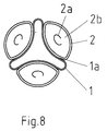
- the heating device has a liquid-conducting pipe 1 and three tubular heating elements 2 with a circular cross-section.
- Contact surfaces 1a of the liquid-conducting tube 1 are arc-shaped in a concave manner, the radius of curvature of the contact surfaces 1a corresponding to the radius of curvature of the heating tubes 2.
- the ratio of the heated circumference to the entire circumference of the tube 1 is about 0.74;
- the ratio of the heated circumference in mm to the cross section in mm 2 is 0.7.
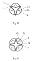
- FIG. 10 and 11 also show tubular heater with concave outer wall; this is not continuous arcuate but at an obtuse angle abutting planar wall portions of the tube 1. This also allows a fairly large ratio of heated circumference to cross section (in mm or in mm 2 ) can be achieved.
- three tubular heating elements 2 are present, whereas in FIG. 11 four tubular heating elements are provided, each of which transmits both to a flow tube 1 and in this heat.
Landscapes
- Engineering & Computer Science (AREA)
- Physics & Mathematics (AREA)
- Thermal Sciences (AREA)
- Mechanical Engineering (AREA)
- General Engineering & Computer Science (AREA)
- Life Sciences & Earth Sciences (AREA)
- Sustainable Development (AREA)
- Sustainable Energy (AREA)
- Food Science & Technology (AREA)
- Instantaneous Water Boilers, Portable Hot-Water Supply Apparatuses, And Control Of Portable Hot-Water Supply Apparatuses (AREA)
- Resistance Heating (AREA)
- Central Heating Systems (AREA)
Applications Claiming Priority (2)
| Application Number | Priority Date | Filing Date | Title |
|---|---|---|---|
| DE20120611U DE20120611U1 (de) | 2001-12-20 | 2001-12-20 | Heizsystem für einen Dampferzeuger |
| EP02028286.9A EP1321708B2 (fr) | 2001-12-20 | 2002-12-17 | Dispositif pour chauffer un liquide |
Related Parent Applications (1)
| Application Number | Title | Priority Date | Filing Date |
|---|---|---|---|
| EP02028286.9A Division EP1321708B2 (fr) | 2001-12-20 | 2002-12-17 | Dispositif pour chauffer un liquide |
Publications (1)
| Publication Number | Publication Date |
|---|---|
| EP1936266A2 true EP1936266A2 (fr) | 2008-06-25 |
Family
ID=7965411
Family Applications (2)
| Application Number | Title | Priority Date | Filing Date |
|---|---|---|---|
| EP02028286.9A Expired - Lifetime EP1321708B2 (fr) | 2001-12-20 | 2002-12-17 | Dispositif pour chauffer un liquide |
| EP07023012A Withdrawn EP1936266A2 (fr) | 2001-12-20 | 2002-12-17 | Dispositif de chauffage d'un liquide et machine à café |
Family Applications Before (1)
| Application Number | Title | Priority Date | Filing Date |
|---|---|---|---|
| EP02028286.9A Expired - Lifetime EP1321708B2 (fr) | 2001-12-20 | 2002-12-17 | Dispositif pour chauffer un liquide |
Country Status (2)
| Country | Link |
|---|---|
| EP (2) | EP1321708B2 (fr) |
| DE (2) | DE20120611U1 (fr) |
Cited By (2)
| Publication number | Priority date | Publication date | Assignee | Title |
|---|---|---|---|---|
| CN105423048A (zh) * | 2015-12-23 | 2016-03-23 | 厦门市好泵机电设备有限公司 | 扁弧管形伴热输油管 |
| WO2025155263A1 (fr) * | 2024-01-15 | 2025-07-24 | Karaca Züccaci̇ye Ti̇caret Ve Sanayi̇ Anoni̇m Şi̇rketi̇ | Machine à café turc |
Families Citing this family (11)
| Publication number | Priority date | Publication date | Assignee | Title |
|---|---|---|---|---|
| DE102004004821A1 (de) | 2004-01-30 | 2005-08-18 | BSH Bosch und Siemens Hausgeräte GmbH | Kaffeemaschine mit Durchlauferhitzer |
| DE102005050203B4 (de) | 2005-10-18 | 2018-05-24 | Eichenauer Heizelemente Gmbh & Co. Kg | Verfahren zur Herstellung eines Durchflusserhitzers und Durchflusserhitzer |
| DE102007001265A1 (de) * | 2007-01-08 | 2008-07-10 | Pavao Paukovic | Elektroheizgerät für durchfließende Flüssigkeiten und Gase |
| DE202009015187U1 (de) * | 2008-11-14 | 2010-06-24 | Koninklijke Philips Electronics N.V. | Einsatzteil für einen Durchlauferhitzer |
| DE102009036070A1 (de) | 2009-08-04 | 2011-02-17 | Eichenauer Heizelemente Gmbh & Co. Kg | Durchflusserhitzer |
| DE202010006739U1 (de) | 2010-05-12 | 2010-08-19 | Türk & Hillinger GmbH | Durchlauferhitzer |
| EP2407069A1 (fr) | 2010-07-12 | 2012-01-18 | Bleckmann GmbH & Co. KG | Chauffe-eau instantané dynamique |
| DE102011007542B4 (de) | 2011-04-15 | 2023-01-12 | Eichenauer Heizelemente Gmbh & Co. Kg | Durchlauferhitzer |
| CN104411218B (zh) | 2012-05-15 | 2020-07-07 | 布莱克曼两合公司 | 饮料制备装置、流过加热器设备及其生产方法 |
| EP2896882B1 (fr) * | 2014-01-15 | 2022-06-01 | Electrolux Appliances Aktiebolag | Générateur de vapeur et appareil électroménager |
| IT201800004614A1 (it) * | 2018-04-17 | 2019-10-17 | Riscaldatore elettrico per frigorifero ad assorbimento |
Citations (3)
| Publication number | Priority date | Publication date | Assignee | Title |
|---|---|---|---|---|
| DE2218796A1 (de) | 1972-04-18 | 1973-10-31 | Bosch Siemens Hausgeraete | Durchlauferhitzer |
| EP0684006A1 (fr) | 1994-05-25 | 1995-11-29 | Kwangju Electronics Co. Limited | Aspirateur avec dispositif émetteur de vapeur |
| DE19945577A1 (de) | 1999-09-23 | 2001-04-05 | Cognis Deutschland Gmbh | Kosmetische und/oder pharmazeutische Zubereitungen |
Family Cites Families (26)
| Publication number | Priority date | Publication date | Assignee | Title |
|---|---|---|---|---|
| FR745341A (fr) * | 1933-05-09 | |||
| DE333670C (de) * | 1918-09-06 | 1921-03-01 | Hermann Pfenninger Roth | Wasserverdampfungsanlage mit elektrischer Waermespeicherung |
| US1509042A (en) † | 1922-11-06 | 1924-09-16 | William M R Kay | Electric water heater |
| US1926958A (en) * | 1932-02-15 | 1933-09-12 | Electric Steam Sterilizing Com | Steam generator |
| GB886189A (en) * | 1959-02-26 | 1962-01-03 | Atomic Energy Authority Uk | Improvements in or relating to liquid evaporating apparatus |
| DE1139589B (de) † | 1960-02-10 | 1962-11-15 | Siemens Elektrogeraete Gmbh | Elektrischer Durchlauferhitzer, bei dem die durchstroemende Fluessigkeit von schraubenfoermig eng aneinanderliegend angeordneten Rohrheizkoerpern erhitzt wird |
| DE1975794U (de) * | 1961-03-15 | 1967-12-28 | Siemens Elektrogeraete Gmbh | Elektrischer durchlauferhitzer. |
| DE1905694U (de) † | 1964-10-03 | 1964-12-03 | Stiebel Werke G M B H & Co Dr | Elektroheisswasserbereiter. |
| DE1753184A1 (de) * | 1968-01-09 | 1971-06-09 | Menzel Heinrich | Elektro-Waermespeicher mit eingebauter Heizkammer |
| DE2339096A1 (de) † | 1973-08-02 | 1975-02-13 | Stiebel Eltron Gmbh & Co Kg | Elektrisch beheizter durchlauferhitzer und verfahren zu seiner herstellung |
| DE2652656C3 (de) * | 1976-11-19 | 1980-04-30 | Tuerk & Hillinger Gmbh & Co, 7200 Tuttlingen | Elektrischer Durchlauferhitzer für flüssige Medien und Verfahren zu seiner Herstellung |
| DE2655788A1 (de) * | 1976-12-09 | 1978-06-15 | Eichenauer Fa Fritz | Verdampfereinrichtung fuer getraenkebereitungsmaschinen, insbesondere elektrische kaffeemaschinen |
| US4246871A (en) * | 1979-05-04 | 1981-01-27 | Bocksruker Ronald W | Steam generator |
| DE3119630A1 (de) * | 1981-05-16 | 1982-12-02 | Fritz Eichenauer GmbH & Co KG, 6744 Kandel | Rohr, insbesondere verdampferrohr fuer elektrische kaffeemaschinen |
| DE3120682A1 (de) * | 1981-05-23 | 1982-12-16 | Horst 5241 Elben Hammes | Elektrisch beheizter zwangsdurchlauferhitzer |
| DE3221348A1 (de) † | 1982-06-05 | 1983-12-08 | E.G.O. Elektro-Geräte Blanc u. Fischer, 7519 Oberderdingen | Heizelement mit zylindrischer wandung |
| DE3320474A1 (de) * | 1983-06-07 | 1984-12-13 | Forbach GmbH, 8740 Bad Neustadt | Waermetauscher fuer fluessige medien |
| DE8529085U1 (de) * | 1985-10-12 | 1985-11-28 | Türk & Hillinger GmbH, 7200 Tuttlingen | Elektrischer Durchlauferhitzer |
| DE3818844C1 (fr) * | 1988-06-03 | 1989-08-24 | Walter 7300 Esslingen De Jost | |
| DE8906033U1 (de) * | 1989-05-16 | 1989-07-20 | Türk & Hillinger GmbH, 78532 Tuttlingen | Elektrischer Durchlauferhitzer |
| DE4212074C1 (en) * | 1992-04-10 | 1993-04-29 | Tuerk & Hillinger Gmbh, 7200 Tuttlingen, De | Electric continuous flow meter e.g. for coffee machine - has tubular heaters pressed so that walls of flow tube have recesses altering cross-section |
| DE9218448U1 (de) † | 1992-07-14 | 1994-04-21 | Elpag Ag Chur, Chur | Durchlauferhitzer mit Flächenberührung zwischen Rohrheizkörper und Mantelrohr |
| DE4226325C1 (de) * | 1992-08-08 | 1993-09-30 | Tuerk & Hillinger Gmbh | Elektrischer Durchlauferhitzer |
| DE9404908U1 (de) * | 1994-03-23 | 1994-05-26 | Fritz Eichenauer Gmbh & Co Kg, 76870 Kandel | Elektrischer Durchlauferhitzer mit Innenbeschichtung des Wasserduchlaufrohres |
| US6442341B1 (en) * | 2000-11-27 | 2002-08-27 | Chia-Hsiung Wu | Simple-type fluid heating tube structural arrangement |
| DE20021754U1 (de) * | 2000-12-22 | 2001-02-22 | Hsieh, Yung-Lung, Hsin-Chuang, Taipeh | Verbesserter Aufbau der Erhitzungstechnik in einem explosionssicheren Dampf |
-
2001
- 2001-12-20 DE DE20120611U patent/DE20120611U1/de not_active Expired - Lifetime
-
2002
- 2002-12-17 EP EP02028286.9A patent/EP1321708B2/fr not_active Expired - Lifetime
- 2002-12-17 EP EP07023012A patent/EP1936266A2/fr not_active Withdrawn
- 2002-12-17 DE DE50212009T patent/DE50212009D1/de not_active Expired - Lifetime
Patent Citations (3)
| Publication number | Priority date | Publication date | Assignee | Title |
|---|---|---|---|---|
| DE2218796A1 (de) | 1972-04-18 | 1973-10-31 | Bosch Siemens Hausgeraete | Durchlauferhitzer |
| EP0684006A1 (fr) | 1994-05-25 | 1995-11-29 | Kwangju Electronics Co. Limited | Aspirateur avec dispositif émetteur de vapeur |
| DE19945577A1 (de) | 1999-09-23 | 2001-04-05 | Cognis Deutschland Gmbh | Kosmetische und/oder pharmazeutische Zubereitungen |
Cited By (2)
| Publication number | Priority date | Publication date | Assignee | Title |
|---|---|---|---|---|
| CN105423048A (zh) * | 2015-12-23 | 2016-03-23 | 厦门市好泵机电设备有限公司 | 扁弧管形伴热输油管 |
| WO2025155263A1 (fr) * | 2024-01-15 | 2025-07-24 | Karaca Züccaci̇ye Ti̇caret Ve Sanayi̇ Anoni̇m Şi̇rketi̇ | Machine à café turc |
Also Published As
| Publication number | Publication date |
|---|---|
| DE20120611U1 (de) | 2003-02-13 |
| EP1321708B1 (fr) | 2008-04-02 |
| EP1321708A3 (fr) | 2004-04-21 |
| EP1321708B2 (fr) | 2013-10-23 |
| EP1321708A2 (fr) | 2003-06-25 |
| DE50212009D1 (de) | 2008-05-15 |
Similar Documents
| Publication | Publication Date | Title |
|---|---|---|
| EP1321708B1 (fr) | Dispositif pour chauffer un liquide | |
| EP2197328B1 (fr) | Chaudière pour faire chauffer l'eau dans des machines à café | |
| EP0531699A1 (fr) | Bouilloire | |
| EP0228000B1 (fr) | Chauffe-eau instantané électrique | |
| EP0238955B1 (fr) | Dispositif de chauffage de fluides | |
| EP2861914B1 (fr) | Chauffe-eau instantané | |
| EP3016114B1 (fr) | Resistance electrique refroidie | |
| EP1529470A1 (fr) | Module de chauffage avec surface chauffante et chaudière instantanée et procédé pour sa fabrication | |
| EP2042821B1 (fr) | Echangeur thermique | |
| EP0221575A1 (fr) | Appareil de chauffage et/ou à cuire avec un bloc d'accumulation de chaleur | |
| DE102011007542A1 (de) | Durchlauferhitzer | |
| EP2053951B1 (fr) | Chauffe-eau, en particulier pour une machine à café | |
| DE202006015593U1 (de) | Vorrichtung zum Erhitzen einer Flüssigkeit und Dampferzeuger mit einer solchen Vorrichtung | |
| EP1964496B1 (fr) | Chauffe-eau instantané | |
| EP1703227B1 (fr) | Echangeur de chaleur | |
| DE60006441T2 (de) | Heizkörper für eine Espresso-Kaffeemaschine | |
| DE1802729C3 (de) | Vorrichtung zum Erhitzen von Flüssigkeiten beziehungsweise Gasen | |
| DE2701692A1 (de) | Elektrischer durchlauferhitzer zur heisswasserbereitung, insbesondere fuer kaffee- oder teebereiter | |
| DE202007017796U1 (de) | Sicherungsvorrichtung für einen Durchlauferhitzer | |
| DE9406423U1 (de) | Heizeinsatz eines elektrischen Durchlauferhitzers | |
| AT407727B (de) | Druckplatte für hydraulische pressen | |
| DE19927057A1 (de) | Durchflußheizung und Kaffeemaschine mit einer solchen | |
| WO2026021815A1 (fr) | Dispositif de chauffage d'eau et appareil ménager à circulation d'eau équipé d'un tel dispositif de chauffage | |
| DE1905694U (de) | Elektroheisswasserbereiter. | |
| DE2628735A1 (de) | Durchlauferhitzer |
Legal Events
| Date | Code | Title | Description |
|---|---|---|---|
| PUAI | Public reference made under article 153(3) epc to a published international application that has entered the european phase |
Free format text: ORIGINAL CODE: 0009012 |
|
| 17P | Request for examination filed |
Effective date: 20071128 |
|
| AC | Divisional application: reference to earlier application |
Ref document number: 1321708 Country of ref document: EP Kind code of ref document: P |
|
| AK | Designated contracting states |
Kind code of ref document: A2 Designated state(s): DE FR IT NL |
|
| STAA | Information on the status of an ep patent application or granted ep patent |
Free format text: STATUS: THE APPLICATION HAS BEEN WITHDRAWN |
|
| 18W | Application withdrawn |
Effective date: 20081227 |