EP1936405B1 - Dispositif et procédé destinés à effacer une couche d'enregistrement luminescente et système avec un tel dispositif et un détecteur - Google Patents
Dispositif et procédé destinés à effacer une couche d'enregistrement luminescente et système avec un tel dispositif et un détecteur Download PDFInfo
- Publication number
- EP1936405B1 EP1936405B1 EP06126941A EP06126941A EP1936405B1 EP 1936405 B1 EP1936405 B1 EP 1936405B1 EP 06126941 A EP06126941 A EP 06126941A EP 06126941 A EP06126941 A EP 06126941A EP 1936405 B1 EP1936405 B1 EP 1936405B1
- Authority
- EP
- European Patent Office
- Prior art keywords
- image
- image signals
- phosphor layer
- storage phosphor
- image information
- Prior art date
- Legal status (The legal status is an assumption and is not a legal conclusion. Google has not performed a legal analysis and makes no representation as to the accuracy of the status listed.)
- Not-in-force
Links
Images


Classifications
-
- G—PHYSICS
- G01—MEASURING; TESTING
- G01T—MEASUREMENT OF NUCLEAR OR X-RADIATION
- G01T1/00—Measuring X-radiation, gamma radiation, corpuscular radiation, or cosmic radiation
- G01T1/16—Measuring radiation intensity
- G01T1/20—Measuring radiation intensity with scintillation detectors
- G01T1/2012—Measuring radiation intensity with scintillation detectors using stimulable phosphors, e.g. stimulable phosphor sheets
- G01T1/2016—Erasing of stimulable sheets, e.g. with light, heat or the like
Definitions
- the present invention relates to a device and a corresponding system and method for erasing a storage phosphor layer according to the preamble of claims 1, 12 and 14, respectively.
- an image is generated for medical purposes from an object, for example a patient or a body part of the patient, by means of X-ray irradiation, which image is stored in a storage phosphor layer as a latent X-ray image.
- a storage phosphor layer as a latent X-ray image.
- Such an X-ray image thus contains image information about the object.
- the storage phosphor layer is excited by means of an irradiation device. Due to this excitation, the storage phosphor layer emits emission radiation which has an intensity corresponding to the amount of image information of the X-ray image stored in the storage phosphor layer.
- the emission radiation emitted by the storage phosphor layer is detected by a detector and converted into electrical signals which contain an image of the image information.
- the electrical signals are further processed and the image information stored in the storage phosphor layer subsequently made visible.
- the image information can be directly on a Monitor can be displayed or written by means of a printer that can be used specifically for X-ray images on a photographic X-ray film.
- a radiation source is used which emits an erasing radiation onto the storage phosphor layer.
- an erase dose of the erasure radiation is preset manually or automatically on the basis of an x-ray dose used in the acquisition of the x-ray image before the image information is read or before the subsequent erasure of the storage phosphor layer.
- an x-ray dose used in the acquisition of the x-ray image before the image information is read or before the subsequent erasure of the storage phosphor layer.
- a uniform and complete deletion of residual information stored in the storage phosphor layer can not be guaranteed in all cases. This is especially true in cases where the erase dose has been mistakenly incorrectly set or in which an unexpectedly large amount of X-ray image information is stored in parts of the storage phosphor layer.
- the control device of the device according to the invention is designed such that it determines an erase dose of the erasing radiation for erasing the storage phosphor layer as a function of image information, previously read from the storage phosphor layer, of an X-ray image stored in the storage phosphor layer.
- a drive device for generating a relative movement between the storage phosphor layer and the detector is present and connected to the control device.
- the control device is designed in such a way that, for generating first image signals, it reads the first image information of the image layer stored in the storage phosphor layer Represent X-ray image, the drive means for generating a first relative movement drives.
- the relative movement can be carried out advantageously reliably, very accurately and in particular very uniformly.
- the first relative movement is carried out in particular in a feed direction.
- the control device is further configured such that it drives the drive device for generating a second relative movement for generating second image signals, which represent second image information of the x-ray image stored in the storage phosphor layer. This advantageously makes it possible to use the second image signals to determine the quenching dose of the quenching radiation.
- control device is designed such that it subjects the first image signals and / or the second image signals to local filtering and superimposes the optionally locally filtered first image signals and second image signals.
- the control device changes image signal values of pixels of the first image signals or the second image signals as a function of image signal values of adjacent pixels.
- This local filtering ensures improved image quality.
- the local filtering may in particular with linear filter operations, such. As a mean value filter performed. This advantageously increases the signal-to-noise ratio at low spatial frequencies.
- the local filtering can in particular with non-linear filtering operations such. As a median filter, performed. This advantageously ensures a sharpening of edges in the X-ray image read.
- the system according to the invention contains the device according to the invention and a detector for detecting emission radiation which outputs the storage phosphor layer during the reading out of image information.
- the extinguishing dose of the erasure radiation is determined as a function of image information of the X-ray image stored in the storage phosphor layer, wherein the image information was previously read out of the storage phosphor layer.
- the method according to the invention is further characterized in that a drive device connected to a control device generates a relative movement between the storage phosphor layer and a detector and the control device for generating first and second image signals drives the drive device for generating a first or second relative movement, wherein the first and second image signals respectively representing first and second image information of the X-ray image read out of the storage phosphor layer, and subjecting the first image signals and / or the second image signals to local filtering, wherein the control means applies image signal values of pixels of the first image signals and the second image signals, respectively Altered dependence of image signal values of adjacent pixels and superimposed on the optionally locally filtered first image signals and second image signals.
- a particularly uniform and complete erasure of residual information remaining in the storage phosphor layer after the image information of the X-ray image has been read out can advantageously be ensured.
- This ensures that when recording a new X-ray image with the storage phosphor layer stored in the storage phosphor layer image information of the X-ray image very closely the structures of a X-rayed object, such. B. a body part of a patient correspond. Distortions and distortions due to residual information present in the storage phosphor layer can advantageously be almost completely avoided. As a result, a very good image quality can be achieved when reading out the stored image information of the X-ray image.
- the control device is used in particular for controlling the radiation source in order to set the quenching dose at the radiation source.
- the extinguishing dose results from the intensity of the erasing radiation and the time duration in which the erasing radiation acts on the storage phosphor layer.
- the extinguishing dose of the extinguishing radiation is advantageously determined automatically by the control device.
- the radiation source comprises an erase lamp which emits erase radiation substantially over the entire width of the storage phosphor layer.
- the radiation source comprises a multiplicity of light sources which emit erasure radiation and are preferably arranged in one or more rows or rows extending across the width of the storage phosphor layer.
- light-emitting diodes LEDs are suitable as light sources, since their heat loss compared to incandescent lamps or the like is low and thus undesired heating of the device and / or the storage phosphor layer during extinguishment can be avoided.
- a radiation source composed of individual light sources it is possible to individually control the light sources, so that the intensity of the erasing radiation emitted by the individual light sources can be set individually and as a function of image information of the X-ray image stored in the storage phosphor layer previously read from the storage phosphor layer. In this way, it is possible to locally select the extinction dose as a function of the previously read X-ray image.
- the control device is designed such that it evaluates the image information read from the storage phosphor layer to determine whether a detector for detecting emission radiation that outputs the storage phosphor layer during readout of the image information was in a saturation or override state. The control device then determines the deletion dose as a function of this evaluation of the read-out image information.
- the fact of whether the detector is in the saturation or overdrive condition is advantageously quickly and reliably detected in a simple manner. If the detector was in the saturation or override state, it can be assumed in particular that a relatively high amount of image information is stored at least in regions in the storage phosphor layer. The controller may thus suitably adjust the erase dose to this relatively high amount of image information.
- the detector If the detector is in the saturation or override state, then it can not completely detect the emission radiation emitted by the storage phosphor layer with the image information read out. In particular, in this case, the absorption capacity of the detector, or individual detector elements of the detector, completely exhausted, so that it can not absorb further emission radiation. In this case, it is thus possible that the detector only partially detects a quantity of image information of the X-ray image read out at at least one location or in a region of the storage phosphor layer. The read-out image information is thus "cut off”. This effect is also called “clipping". The amount of detected emission radiation does not correspond to the amount of emission radiation emitted by the storage phosphor layer. In particular, no amount of emission radiation corresponding to the image information stored in the storage phosphor layer is detected by the detector.
- the control device is designed such that it evaluates the first image signals, which represent the read-out first image information, as to whether the detector was in the saturation or override state when the first image information for generating the first image signals was read. Even these first image signals, which represent the read-out first image information, can enable a good estimation of the erasure dose to be advantageously used for erasure.
- the control device is designed such that it determines a first erase dose, provided that the evaluation of the first image signals shows that the detector was not in the saturation or overdrive state when reading out the first image information for generating the first image signals.
- This first erase dose can be chosen to be relatively low because no particularly large amount of emission radiation has been emitted from the storage phosphor layer when reading the image information. In this case, it is advantageously possible to dispense with carrying out a further read-out process for reading out stored image information of the x-ray image.
- the evaluation of the first image signals is completely sufficient for determining the appropriate erase dose. The deletion of the storage phosphor layer can thus be done quickly and reliably. Furthermore, the energy required for the low first extinguishing dose for extinguishment is low.
- the first image signals are derived from the acquired first image information by a first processing method and the second image signals are derived from the acquired second image information by a second processing method, wherein the first and second processing methods differ.
- the first and second processing methods differ here, in particular, in that they take into account the intensities of the emission light excited in the storage phosphor layer when the first or second image information is detected to be of a different intensity. These differences in intensity result from the fact that the intensity of the emission light due to the so-called destructive read-out during the detection of the first image information in the subsequent detection of the second image information is smaller.
- the control device is designed such that it evaluates the second image signals representing the read second image information, and determines a second erase dose that is greater than the first erase dose, if the evaluation of the second image signals shows that the detector when reading the first image information for generating the first image signals in the saturation or overdrive state and in the readout the second image information for generating the second image signals was not in the saturation or overdrive state.
- the second deletion dose may have a medium height. This further enables a fast and reliable extinguishing and limits the energy expenditure to be used for the mean second extinguishing dose.
- the control device is designed such that it determines a third erase dose, which is greater than the second erase dose, if the evaluation of the second image signals shows that the detector when reading the second image information for generating the second image signals in the Saturation or overdrive condition.
- the storage phosphor layer emitted during reading a particularly large amount of emission radiation. It is therefore assumed that a large amount of X-radiation has penetrated into the storage phosphor layer when taking the X-ray image.
- a relatively large amount of further image information of the X-ray image is stored in the storage phosphor layer. This relatively large amount of further image information is then to be regarded as residual information to be deleted, for the deletion of which a high quenching dose is thus used. This ensures reliable erasure of the storage phosphor layer.
- a direction of the first relative movement is opposite to a direction of the second relative movement.
- the reading of the first image information can thus advantageously be done on a way or a trace and read the second image information on a return or a return.
- control device is configured such that it transforms the first image signals and / or the second image signals into the frequency domain by means of a Fourier transformation and subject them to further processing in the frequency domain.
- This makes it possible for the To process image signals frequency dependent in a suitable manner. This enables a particularly high image quality of the X-ray image read from the storage phosphor layer.
- the Fourier-transformed first and second image signals can already be superimposed in the frequency domain and optionally scaled.
- only the second image signals are transformed into the frequency domain by means of the Fourier transformation and further processed in the frequency domain. This limits the effort and still ensures a very high image quality.
- the further processing comprises filtering, in particular filtering with a low pass.
- filtering By filtering noise and noise components of the image signals can be removed, whereby a very good image quality of the read out of the storage phosphor layer X-ray image can be ensured.
- filtering with the low pass in particular high-frequency components of the image signals in the Fourier spectrum can be suppressed or at least attenuated. In this case, the signal-to-noise ratio is advantageously increased.
- control device is designed such that it transforms back the Fourier-transformed and processed first image signals and / or second image signals into the spatial domain and superimposes the first image signals and second image signals.
- the superposition of the first image signals with the second image signals takes place in particular pointwise and advantageously enables a particularly accurate reproduction of the image information of the X-ray image actually stored in the storage phosphor layer.
- the control device is particularly preferably designed such that it evaluates the read first image signal representing first image signals as to whether they have at least one location or region in which the detector reads out the first image information for generating this at least one region of the first image signals in the first image information Saturation or overdrive state, and at least one location or region of the second image signals representing the read second image information is used to replace the at least one region of the first image signals.
- a point or a region in the read-out X-ray image which could not be completely detected by the first image signals due to the "clipping" effect, can be derived at least approximately by means of the second image signals.
- a realistic reproduction of the X-ray image stored in the storage phosphor layer is advantageously possible.
- Replacing the location or range of the first image signals with the location or range of the second image signals is also referred to as a "patch" function.
- Fig. 1 shows a schematic, perspective view of an embodiment of a device according to the invention for deleting stored in a storage phosphor layer residual information of an X-ray image.
- the device is designed here as a radiographic module 1, which also serves as a read-out device for reading out image information of the x-ray image stored in the storage phosphor layer.
- the residual information to be deleted is that information which remains in the storage phosphor layer after reading the image information. After deleting the remaining information, the storage phosphor layer can be used for a new X-ray image.
- the radiography module 1 is here preferably designed and handled like an X-ray cassette. D. h., It is essentially portable and can be used to record X-ray images in different X-ray systems, such. B.
- the radiography module 1 is pivotable. For reading out the X-ray image stored in the storage phosphor layer, the radiography module 1 can remain in the X-ray system and does not have to be removed from the X-ray system like a conventional X-ray cassette and fed to a separate read-out station.
- the radiographic module 1 comprises a housing 2, in which a storage phosphor plate 3 is arranged.
- the storage phosphor plate 3 has a storage phosphor layer 4 and a carrier layer on which the storage phosphor layer 4 is applied ( Fig. 2 ).
- the storage phosphor layer 4 is here the upper layer of the storage phosphor plate 3.
- the storage phosphor plate 3 is fixedly arranged in the housing 2 of the radiography module 1, ie the storage phosphor plate 3 is connected via suitable connecting elements fixed to the housing 2.
- the connection with the housing 2 may be rigid or oscillating, z. B. by means of suitable suspension elements, to dampen any external shocks on the housing 2 and their transmission to the storage phosphor plate 3.
- the radiography module 1 contains a reading head 5 for reading out the image information of the X-ray image from the storage phosphor layer 4.
- the reading head 5 is movably mounted in the housing 2.
- 3 guides 6 and 7 are arranged in the region of the two longitudinal sides of the storage phosphor plate, which serve the reading head 5 as a bearing, preferably in the form of air bearings, and leadership.
- a suitable drive 8 z. B. a linear drive with a very accurate transmission, driven and moved in a first transport direction T in a Hinlaufraum and in a second transport direction R in a return direction on the storage phosphor plate 3.
- a first relative movement in the first transport direction T and a second relative movement in the second transport direction R take place between the storage phosphor layer 4 and the read head 5 in order to read out the stored image information.
- the driving of the reading head 5, and thus the generation and execution of the first and second relative movement between the storage phosphor layer 4 and the reading head 5, takes place continuously and linearly with a very constant transport speed.
- the reading head 5 is movable along the storage phosphor plate 3, while the storage phosphor plate 3 is fixedly arranged in the housing 2.
- an erase lamp 9 is provided, which can also be driven by the drive 8 and moved over the storage phosphor layer 4.
- the erase lamp 9 serves to erase the remaining information in the storage phosphor layer 4, which are still present after readout, before the subsequent X-ray exposure.
- control device 10 which controls the readout and erasure process as well as any signal processing processes.
- various interfaces 11 are present, which are required for transmitting energy, possibly air, control signals and / or image signals to and from the radiography module 1.
- Fig. 2 shows a further schematic representation of a structure of the radiographic module 1 after Fig. 1 ,
- the radiography module 1 is shown here in a side view.
- Shown is the storage phosphor plate 3, which has a carrier layer 12 and the storage phosphor layer 4.
- the storage phosphor layer 4 is preferably composed of a multiplicity of phosphor particles which serve to store the image information of the X-ray image.
- the backing layer 12 may be a laminate composed of various layers and materials.
- the carrier layer 12 is here a transparent carrier layer, which is partially transparent to radiation.
- the reading head 5 contains an irradiation device 13 which serves for irradiating the storage phosphor layer 4 with an excitation radiation 14.
- a laser diode array will be used, which contains a plurality of juxtaposed laser diodes. With this laser diode array, one row of the storage phosphor layer 4 is simultaneously irradiated and excited.
- the storage phosphor layer 4 Due to the excitation of the storage phosphor layer 4 by means of the excitation radiation 14, the storage phosphor layer 4 emits an emission radiation 15 whose intensity depends on the image information stored in the storage phosphor layer 4.
- the reading head 5 includes a detector 16.
- the detector 16 here has a line detector which contains a so-called "charge-coupled device” (CCD) line.
- the CCD line has a large number of parallel in a line next to each other arranged photodetectors, which represent detector elements. The number of adjacent detector elements determines the resolution, and hence the number of dots or pixels, of the detector 16 in the line direction.
- the detector 16 is read out at a predetermined time interval.
- the detector 16 instead of the CCD line, for example, have a light guide with a connected photomultiplier.
- the irradiation device 13 is arranged in the present embodiment below and the detector 16 above the storage phosphor plate 3.
- the irradiation device 13 is the carrier layer 12 and the detector 16 of the storage phosphor layer 4 immediately adjacent.
- the excitation radiation 14 can penetrate into the transparent carrier layer 12 and reach the storage phosphor layer 4 from below.
- the control device 10 includes a first control means 17 for controlling the radiography module 1 and its components.
- the first control means 17 therefore controls, in particular, the functions of the irradiation device 13 and of the detector 16 and of the drive 8.
- the first control means 17 is connected to these components of the radiography module 1.
- the control device 10 contains a second control means 18 for processing the image information read from the storage phosphor layer 12.
- the second control means 18 is in particular connected to the detector 16 in order to detect the electrical signals generated by the detector 16, which image is that of the storage phosphor layer 4 stored image information of the X-ray image included, to process.
- the two control means 17 and 18 can also be realized by a single control means.
- the reading head 5, ie both the irradiation device 13 and the detector 16, is initially moved in the first transport direction T from its rest position by means of the drive 8 at a transport speed along the entire length of the storage phosphor plate 3.
- First image information of the X-ray image stored in the storage phosphor layer 4 is read out on account of the emission radiation 15 received by the detector 16.
- the first image information is converted by the individual detector elements of the detector 16 into electrical first image signals and fed to the second control means 18.
- the reading head 5 may optionally subsequently be moved back into the rest position by means of the drive 8 along the entire length of the storage phosphor plate 3 in the second transport direction R.
- second image information of the X-ray image stored in the storage phosphor layer 4 is read out on account of the emission radiation 15 received by the detector 16.
- the second image information is converted by the individual detector elements of the detector 16 into electrical second image signals and fed to the second control means 18.
- the second control means 18 can preferably decide based on an evaluation of the first image signals.
- the size of the pixels of the X-ray image read, and thus its resolution, results, in the first transport direction T and the second transport direction R considered, inter alia, the transport speed and the predetermined time interval for reading the detector 16.
- the execution of the relative movements in the first transport direction T and the second transport direction R are also referred to as performing subscans.
- the read head 5 for reading the second image information in the first Transport direction T opposite second transport direction R moves.
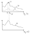
- Fig. 3A shows exemplary schematic, non-normalized representations of a first image signal 20 and a second image signal 21. Plotted are in a coordinate system, the image signals 20, 21 (characterized by an S on the ordinate) via one of the read head 5 when reading the image information along the longitudinal extent of Storage phosphor layer 4 traveled readout path (indicated by an x on the abscissa). The two image signals 20, 21 are thus shown here in a spatial space.
- the first image signal 20 was generated by one of the detector elements of the detector 16 in transporting the read head 5 in the first transport direction T and represents the emission radiation 15 emitted from the storage phosphor layer 4 in transporting the read head 5 in the first transport direction T, from the one of the detector elements of the detector 16 has been detected and recorded.
- the first image signal 20 thus essentially represents those first image information which are stored in the storage phosphor layer 4 along the readout path traveled by the one of the detector elements of the detector 16 during readout in the first transport direction T.
- the second image signal 21 was generated by the one of the detector elements of the detector 16 in transporting the read head 5 in the second transport direction R and represents the emissive radiation 15 emitted from the storage phosphor layer 4 when transporting the read head 5 in the second transport direction R from the one of the Detector elements of the detector 16 was recorded and recorded.
- the second image signal 21 thus essentially represents those second image information which are stored in the storage phosphor layer 4 along the readout path traveled by the one of the detector elements of the detector 16 during readout in the second transport direction R.
- the height of the first image signal 20 is significantly greater than that of the second image signal 21. This is because when first reading the stored image information, a much larger amount of image information is stored in the storage phosphor layer 4, and therefore a much larger amount of emission radiation from the Storage phosphor layer 4 is output, as in the second read.
- the signal-to-noise ratio is significantly better in the first image signal 20 than in the second image signal 21.
- high-frequency distortions are included in the second image signal 21, which are schematically indicated here by vertically extending deflections of the image signal 21.
- the second image signal 21 is subjected to a Fourier transformation in the present exemplary embodiment.
- FIG. 3B shows Fourier-transformed signal and filter characteristics plotted over a frequency f.
- the signal and filter profiles are thus shown in a frequency domain.
- Fig. 3B shows a schematic, non-normalized representation of a Fourier-transformed second image signal 22, which corresponds to a result of the Fourier transform of the second image signal 21.
- Fig. 3B further shows a schematic, non-normalized representation of a curve 23 of a filter for filtering the second image signal 22.
- the filter profile 23 substantially corresponds to a course of a low-pass filter.
- Fig. 3B further shows a schematic, non-normalized representation of a filtered, Fourier-transformed second image signal 24, which corresponds to a result of a filtering of the Fourier-transformed second image signal 22 by means of the filter with the filter curve 23.
- Fig. 3C shows a schematic, non-normalized representation of an in-space transformed, filtered second image signal 25 corresponding to the filtered, Fourier-transformed second image signal 24, which was transformed back into the position space. Also shown is the first image signal 20 and an image signal waveform 26 of a superimposition of the first image signal 20 and the back-transformed, filtered second image signal 25. The superimposition here essentially corresponds to an addition of the first image signal 20 and the back-transformed, filtered second image signal 25.
- first image signal 20 it is possible, in addition to the second image signal 21, to also subject the first image signal 20 to the Fourier transformation and the subsequent filtering with the filter profile 23. It is also possible to superimpose the Fourier-transformed, and optionally filtered, first image signal and second image signal already in the frequency domain and then to transform the superimposed overall image signal back into the spatial domain.
- FIGS. 4A and 4B show schematic diagrams for illustrating a local filtering of image signals. Local filtering is also referred to as performing so-called core or kernel operations.
- a signal value of a pixel of the image signal is manipulated in response to signal values of pixels in its neighborhood.
- the local neighborhood of the pixel in a 3x3 or 5x5 environment is used to calculate the new signal value.
- Fig. 4A shows by way of example a pixel P and its adjacent 3x3 environment.
- Fig. 4B shows by way of example the pixel P and its adjacent 5x5 environment.
- signal values of the second image signals are locally filtered in order to advantageously improve the signal-to-noise ratio.
- Different filter types can be used as local filters. These are in particular linear filters, such as. As a mean value filter with which advantageously the signal-to-noise ratio can be increased at low spatial frequencies. It can also be used non-linear filters, such as. B. median filter, which advantageously a tightening of edges in the read X-ray image can be performed.
- the detector 16, or rather one or more of the detector elements of the detector 16 may enter a saturation or override state. If the detector 16, or individual detector elements, is in this saturation or override state, then it can no longer detect the emission radiation 15 emitted by the storage phosphor layer 4 with the image information read out. In particular, the absorption capacity of the detector 16, or individual detector elements, is completely exhausted, so that it can not absorb any further emission radiation. In this case, the detector elements of the detector 16 only have to be read out again in order to be able to record emission radiation 15 again.
- the detector 16 only partially detects an amount of image information of the X-ray image read out at at least one point or in a region of the storage phosphor layer 4.
- the read-out image information is thus "cut off”. This effect is called “clipping".
- the amount of the detected emission radiation 15 does not correspond to the amount of emission radiation 15 emitted by the storage phosphor layer 4.
- Fig. 5A shows an example of a first image signal 30 generated by one of the detector elements of the detector 16 when transporting the read head 5 in the first transport direction T.
- the first image signal 30 represents the emission radiation 15 emitted by the storage phosphor layer 4 when transporting the read head 5 in the first transport direction T, which was detected by the one of the detector elements of the detector 16.
- the image signal 30 has a region 31 in which the signal profile is "cut off", ie remains constant at a maximum value. This means that when reading out the first image information along a part of the readout path, which defines a width 32 of the region 31 in the x direction, the "clipping" effect occurred in the detector element.
- the emission radiation 15 emitted by the storage phosphor layer 4 was so large that the detector element could no longer absorb part of this emission radiation 15.
- Fig. 5A further shows a second image signal 33 generated by the one of the detector elements of the detector 16 when transporting the read head 5 in the second transport direction R.
- the control device 10 is designed such that it evaluates the first image signal 30, which represents the first image information read out by the one of the detector elements.
- the controller 10 examines the course of the first image signal for locations or areas in which the "clipping" effect occurred, ie in which the detector element was in the saturation or overdrive state when the first image information was read. If the control device 10 finds such a location or area, then it uses the second image signal, the read-out represents second image information, to replace the "clipping" or "clipping" region of the first image signal.
- FIG. 5B 4 shows a first image signal 34 whose signal curve in width 32 is derived from the region of the second image signal 33 which is valid in width 32.
- the image signal 34 thus corresponds to the image signal 30 except for the signal curve in the width 32.
- the signal curve of the image signal 30 has been replaced in the "clipping" region 31 in order to obtain the signal curve of the image signal 34.
- This procedure is called a "patch" function.
- this "patch" function an actual amount of first image information at a location or in a region of the read X-ray image that could not be completely detected by the first image signals due to the "clipping" effect, at least approximately derived by means of the second image signals become.
- a realistic reproduction of the X-ray image stored in the storage phosphor layer is advantageously possible.
- FIG. 6A-6C show schematic representations of read in one or in two read-out first and first and second image information of X-ray images.
- FIG. 2 shows hinted first image information 40 of an X-ray image 41 stored in the storage phosphor layer 4.
- the first image information 40 was obtained in a first read operation by transporting the read head 5 via the storage phosphor layer 4 in the first transport direction T.
- a second read-out process for reading out second image information of the X-ray image 41 by transporting the read head 5 via the storage phosphor layer 4 in the second transport direction R was not performed.
- Fig. 6B shows on the left side suggestively read first image information 42 of a stored in the phosphor layer 4 X-ray image 43.
- the first image information 42 was obtained in a first read-out process by transporting the read head 5 via the storage phosphor layer 4 in the first transport direction T.
- a saturation or overdriving state occurred in the detector 16, resulting in a "clipping" region 44 in the first image information 42.
- Fig. 6B also shows on the right side hinted second image information 45 of the X-ray image 43 stored in the storage phosphor layer 4.
- the second image information 45 was obtained by transporting the read head 5 via the storage phosphor layer 4 in the second transport direction R with a second read operation. In the second image information 45 no "clipping" area occurs anymore.
- Fig. 6C 1 shows on the left side suggestively read out first image information 46 of an X-ray image 47 stored in the storage phosphor layer 4.
- the first image information 46 was obtained in a first read operation by transporting the read head 5 via the storage phosphor layer 4 in the first transport direction T.
- a saturation or overdriving state likewise occurred in the detector 16, so that a "clipping" region 48 was created in the first image information 46.
- Fig. 6C also shows on the right side hinted second image information 49 of the stored in the phosphor layer 4 X-ray image 47.
- the second image information 49 were obtained by transporting the read head 5 via the storage phosphor layer 4 in the second transport direction R with a second read.
- a saturation or override state continued to occur in the detector 16, so that a "clipping" region 50 was formed in the second image information 49.
- Figs. 6A-6C becomes the occurrence of the "clipping" effect and the resulting presence of the "clipping" areas 44, 48 and 50 are used respectively for determining an erasing dose used for erasing the storage phosphor layer 4 by means of the erasing lamp 9 after reading the X-ray images 41, 43 and 47, respectively.
- the extinguishing dose is determined by the intensity of the extinguishing radiation emitted by the extinguishing lamp 9 and the time duration with which the extinguishing lamp 9 irradiates the storage phosphor layer 4 with the extinguishing radiation.
- the control device 10 determines the presence of the "clipping" areas 44, 48 and 50.
- the presence of the "clipping" areas in the read-out first and / or second image information is used here as a measure of the amount of after reading the X-ray images in the storage phosphor layer 4 to estimate remaining information to be deleted.
- the control device 10 sets a low first erase dose in the erase lamp 9 for erasing the storage phosphor layer 4 after reading the X-ray image 41.
- the control device 10 can be designed in such a way that it decides independently on the basis of the first image information 40, and if necessary a presence of a "clipping" region, whether a second read-out process for reading out second image information is carried out. As a rule, the second read-out process will not be executed unless the first image information has a "clipping" area.
- the control device 10 sets to erase the storage phosphor layer 4 after reading the X-ray image 43 preferably a mean second erase dose at the erase lamp 9, which is greater than the first erase dose.
- the second deletion dose but also equal to the first deletion dose, since the second readout due to the so-called destructive read a part of the remaining image information are deleted, which means that the deletion dose for deleting the remaining after the second read operation image information relative to the first Extinguishing dose does not need to be increased.
- the "clipping" area 48 is included.
- the second image information 49 is also a “clipping” area, the "clipping" area 50, available.
- the control device 10 therefore sets to erase the storage phosphor layer 4 after reading the X-ray image 47, a high erase dose at the erase lamp 9, which is preferably greater than the second erase dose.
Landscapes
- Physics & Mathematics (AREA)
- Health & Medical Sciences (AREA)
- Life Sciences & Earth Sciences (AREA)
- General Physics & Mathematics (AREA)
- High Energy & Nuclear Physics (AREA)
- Molecular Biology (AREA)
- Spectroscopy & Molecular Physics (AREA)
- Conversion Of X-Rays Into Visible Images (AREA)
- Apparatus For Radiation Diagnosis (AREA)
- Luminescent Compositions (AREA)
- Measurement Of Radiation (AREA)
Claims (14)
- Dispositif (1) d'effacement d'une couche d'enregistrement luminescente (4) au moyen d'un rayonnement d'effacement, dans lequel le dispositif (1)- comporte une source de rayonnement (9) destinée à produire et à émettre le rayonnement d'effacement, et- présente un dispositif de commande (10) conçu pour déterminer une dose d'effacement du rayonnement d'effacement permettant d'effacer la couche d'enregistrement luminescente (4) en fonction d'informations d'image (40 ; 42, 45 ; 46, 49), lues à partir de la couche d'enregistrement luminescente (4), relatives à une image radiographique (41 ; 43 ; 47) enregistrée dans la couche d'enregistrement luminescente (4), caractérisé en ce qu'il est prévu un dispositif d'entraînement (8) relié au dispositif de commande (10) et destiné à produire un mouvement relatif entre la couche d'enregistrement luminescente (4) et un détecteur (16), et en ce que le dispositif de commande (10) est conçu de manière à commander le dispositif d'entraînement (8) destiné à produire un premier ou second mouvement relatif en vue de produire des premiers et seconds signaux d'image, les premiers et seconds signaux d'image représentant des premières et secondes informations d'image relatives à l'image radiographique respectivement lue à partir de la couche d'enregistrement luminescente (4), et de manière à soumettre les premiers signaux d'image et/ou les seconds signaux d'image à un filtrage local moyennant lequel le dispositif de commande (10) modifie des valeurs de signaux d'image de points d'image des premiers signaux d'image ou des seconds signaux d'image en fonction des valeurs de signaux d'image de points d'image voisins, et superpose les premiers signaux d'image et seconds signaux d'image qui, le cas échéant, ont subi un filtrage local.
- Dispositif selon la revendication 1, caractérisé en ce que le dispositif de commande (10) est conçu de manière à exploiter les informations d'image (40 ; 42, 45 ; 46, 49) lues à partir de la couche d'enregistrement luminescente (4) pour savoir si le détecteur (16), destiné à détecter le rayonnement d'émission (15) émis par la couche d'enregistrement luminescente (4) au cours de la lecture des informations d'image (40 ; 42, 45 ; 46, 49), était dans un état de saturation ou de surcharge, et de manière à déterminer la dose d'effacement en fonction de cette exploitation.
- Dispositif selon la revendication 2, caractérisé en ce que le dispositif de commande (10) est conçu de manière à exploiter les premiers signaux d'image pour savoir si le détecteur (16) était dans l'état de saturation ou de surcharge au cours de la lecture des premières informations d'image visant à produire les premiers signaux d'image.
- Dispositif selon la revendication 3, caractérisé en ce que le dispositif de commande (10) est conçu de manière à déterminer une première dose d'effacement lorsque la vérification des premiers signaux d'image indique que le détecteur (16) n'était pas dans l'état de saturation ou de surcharge lors de la lecture des premières informations d'image (40) visant à produire les premiers signaux d'image.
- Dispositif selon la revendication 3 ou 4, caractérisé en ce que le dispositif de commande (10) est conçu de manière à exploiter les seconds signaux d'image et à déterminer une deuxième dose d'effacement, supérieure ou égale à la première dose d'effacement, lorsque l'exploitation des seconds signaux d'image indique que le détecteur (16) était dans l'état de saturation ou de surcharge au cours de la lecture des premières informations d'image (42 ; 46) visant à produire les premiers signaux d'image et qu'il n'était pas dans l'état de saturation ou de surcharge au cours de la lecture des secondes informations d'image (45 ; 49) visant à produire les seconds signaux d'image.
- Dispositif selon la revendication 5, caractérisé en ce que le dispositif de commande (10) est conçu de manière à déterminer une troisième dose d'effacement, supérieure à la deuxième dose d'effacement, lorsque l'exploitation des seconds signaux d'image indique que le détecteur (16) était dans l'état de saturation ou de surcharge au cours de la lecture des secondes informations d'image (45 ; 49) visant à produire les seconds signaux d'image.
- Dispositif selon l'une des revendications 1 à 6, caractérisé en ce qu'un sens (T) du premier mouvement relatif est opposé à un sens (R) du second mouvement relatif.
- Dispositif selon l'une des revendications 1 à 7, caractérisé en ce que le dispositif de commande (10) est conçu de manière à faire passer les premiers signaux d'image et/ou les seconds signaux d'image, au moyen d'une transformée de Fourier, dans un domaine fréquentiel et à les soumettre dans le domaine fréquentiel à un traitement supplémentaire.
- Dispositif selon la revendication 8, caractérisé en ce que le traitement supplémentaire comprend un filtrage, notamment un filtrage faisant appel à un filtre passe-bas.
- Dispositif selon la revendication 8 ou 9, caractérisé en ce que le dispositif de commande (10) est conçu de manière à faire repasser dans le domaine spatial les premiers signaux d'image et/ou seconds signaux d'image ayant subi la transformée de Fourier et le traitement supplémentaire et à superposer les premiers signaux d'image et les seconds signaux d'image.
- Dispositif selon l'une des revendications 1 à 10, caractérisé en ce que le dispositif de commande (10) est conçu de manière à exploiter les premiers signaux d'image pour savoir s'ils présentent au moins une zone dans laquelle le détecteur (16) était dans l'état de saturation ou de surcharge au cours de la lecture des premières informations d'image (40 ; 42 ; 46) visant à produire cette au moins une zone des premiers signaux d'image, et à utiliser au moins une zone des seconds signaux d'image pour remplacer l'au moins une zone des premiers signaux d'image.
- Système comportant un dispositif (1) selon l'une des revendications précédentes et un détecteur (16) destiné à détecter le rayonnement d'émission (15) émis par la couche d'enregistrement luminescente (4) au cours de la lecture des informations d'image.
- Système selon la revendication 12, caractérisé en ce qu'il dispose d'une couche d'enregistrement luminescente (4).
- Procédé d'effacement d'une couche d'enregistrement luminescente (4) au moyen d'un rayonnement d'effacement, dans lequel- le rayonnement d'effacement est produit et émis par une source de rayonnement (9), et- une dose d'effacement du rayonnement d'effacement est déterminée en fonction des informations d'image (40 ; 42, 45 ; 46, 49) d'une image radiographique (41 ; 43 ; 47) enregistrée dans la couche d'enregistrement luminescente (4), les informations d'image (40 ; 42, 45 ; 46, 49) ayant préalablement été lues à partir de la couche d'enregistrement luminescente (4), caractérisé en ce que
un dispositif d'entraînement (8) relié à un dispositif de commande (10) produit un mouvement relatif entre la couche d'enregistrement luminescente (4) et un détecteur (16) et en ce que le dispositif de commande (10) commande le dispositif d'entraînement (8) destiné à produire un premier et un second mouvement relatif en vue de produire des premiers et seconds signaux d'image, les premiers et seconds signaux d'image représentant des premières et secondes informations d'image relatives à l'image radiographique respectivement lue à partir de la couche d'enregistrement luminescente (4), et il soumet les premiers signaux d'image et/ou les seconds signaux d'image à un filtrage local moyennant lequel le dispositif de commande (10) modifie des valeurs de signaux d'image de points d'image des premiers signaux d'image ou des seconds signaux d'image en fonction des valeurs de signaux d'image de points d'image voisins, et superpose les premiers signaux d'image et seconds signaux d'image qui, le cas échéant, ont subi un filtrage local.
Priority Applications (3)
| Application Number | Priority Date | Filing Date | Title |
|---|---|---|---|
| EP06126941A EP1936405B1 (fr) | 2006-12-21 | 2006-12-21 | Dispositif et procédé destinés à effacer une couche d'enregistrement luminescente et système avec un tel dispositif et un détecteur |
| AT06126941T ATE475111T1 (de) | 2006-12-21 | 2006-12-21 | Vorrichtung und verfahren zum löschen einer speicherleuchtstoffschicht und system mit einer solchen vorrichtung und einem detektor |
| DE502006007493T DE502006007493D1 (de) | 2006-12-21 | 2006-12-21 | Vorrichtung und Verfahren zum Löschen einer Speicherleuchtstoffschicht und System mit einer solchen Vorrichtung und einem Detektor |
Applications Claiming Priority (1)
| Application Number | Priority Date | Filing Date | Title |
|---|---|---|---|
| EP06126941A EP1936405B1 (fr) | 2006-12-21 | 2006-12-21 | Dispositif et procédé destinés à effacer une couche d'enregistrement luminescente et système avec un tel dispositif et un détecteur |
Publications (2)
| Publication Number | Publication Date |
|---|---|
| EP1936405A1 EP1936405A1 (fr) | 2008-06-25 |
| EP1936405B1 true EP1936405B1 (fr) | 2010-07-21 |
Family
ID=37834201
Family Applications (1)
| Application Number | Title | Priority Date | Filing Date |
|---|---|---|---|
| EP06126941A Not-in-force EP1936405B1 (fr) | 2006-12-21 | 2006-12-21 | Dispositif et procédé destinés à effacer une couche d'enregistrement luminescente et système avec un tel dispositif et un détecteur |
Country Status (3)
| Country | Link |
|---|---|
| EP (1) | EP1936405B1 (fr) |
| AT (1) | ATE475111T1 (fr) |
| DE (1) | DE502006007493D1 (fr) |
Families Citing this family (2)
| Publication number | Priority date | Publication date | Assignee | Title |
|---|---|---|---|---|
| EP2461184B1 (fr) | 2010-12-03 | 2015-07-08 | Agfa HealthCare N.V. | Dispositif et procédé destinés à l'extraction d'informations radiographiques stockées sur un disque fluorescent de mémoire |
| EP2793054A1 (fr) * | 2013-04-16 | 2014-10-22 | Agfa HealthCare N.V. | Procédé et dispositif destinés à la lecture d'informations radiographiques stockées sur une couche fluorescente de mémoire |
Family Cites Families (7)
| Publication number | Priority date | Publication date | Assignee | Title |
|---|---|---|---|---|
| JPS60260035A (ja) | 1984-06-06 | 1985-12-23 | Fuji Photo Film Co Ltd | 蓄積性螢光体シ−トの残像消去方法および装置 |
| US4786808A (en) | 1985-03-11 | 1988-11-22 | Fuji Photo Film Co., Ltd. | Residual image erasing apparatus for stimulable phosphor sheet |
| US5072119A (en) | 1990-04-18 | 1991-12-10 | Fuji Photo Film Co., Ltd. | Radiation image read-out apparatus and erasing apparatus |
| JP3441578B2 (ja) * | 1995-11-22 | 2003-09-02 | 株式会社モリタ製作所 | 歯科用パノラマx線撮影装置 |
| US5818065A (en) * | 1996-02-08 | 1998-10-06 | Agfa-Gevaert | Radiation image readout method and apparatus |
| JP2000004398A (ja) * | 1998-06-16 | 2000-01-07 | Fuji Photo Film Co Ltd | 画像処理方法および装置 |
| WO2006050019A1 (fr) * | 2004-10-29 | 2006-05-11 | Orex Computed Radiography Ltd. | Procede et dispositif de lecture d'images a partir d'une feuille de stockage au phosphore |
-
2006
- 2006-12-21 EP EP06126941A patent/EP1936405B1/fr not_active Not-in-force
- 2006-12-21 AT AT06126941T patent/ATE475111T1/de active
- 2006-12-21 DE DE502006007493T patent/DE502006007493D1/de active Active
Also Published As
| Publication number | Publication date |
|---|---|
| DE502006007493D1 (de) | 2010-09-02 |
| EP1936405A1 (fr) | 2008-06-25 |
| ATE475111T1 (de) | 2010-08-15 |
Similar Documents
| Publication | Publication Date | Title |
|---|---|---|
| EP1322143A2 (fr) | Procédé et dispostif d'exposition des radiographies | |
| DE19748891A1 (de) | Verfahren und Vorrichtung zur Modifizierung einer Schnittdicke während einer Wendelabtastung | |
| DE69129868T2 (de) | Verfahren und Gerät zur Glättung von Bildern | |
| EP1262147B1 (fr) | Appareil et méthode d'ajustement d'une dose de rayonnement d'une source de rayons X | |
| DE2720994C2 (de) | Vorrichtung zum Rekonstruieren von Tomogrammen | |
| EP1691216B1 (fr) | Système radiographique et méthode d'enregistrement des radiographies dans des feuilles photostimulables | |
| EP1804081B1 (fr) | Dispositif destiné à la lecture d'informations radiographiques stockées dans une couche fluorescente de mémoire et module de radiographie | |
| EP1936405B1 (fr) | Dispositif et procédé destinés à effacer une couche d'enregistrement luminescente et système avec un tel dispositif et un détecteur | |
| EP1691215B1 (fr) | Procédé et appareil pour lire des vues radiographiques enregistrées dans des écrans luminescents | |
| DE102004017804B4 (de) | Bildpuffer und Zugriffszeitpläne für Bildrekonstruktionspläne | |
| DE69424136T2 (de) | Verfahren und Anordnung zur Bearbeitung von Überlagerungsstrahlungsbildern | |
| EP2290404B1 (fr) | Procédé et appareil de lecture et d'effacage de l'effet d'un rayonnnement X sur un écran photostimulable | |
| EP1494067B1 (fr) | Système comprenant un scanner et une couche de stockage, ainsi qu'une couche de stockage pour mémoriser des informations radiographiques | |
| EP1507151A1 (fr) | Dispositif pour la réproduction d'images dans un écran luminescent stimulable | |
| EP1621899B1 (fr) | Procédé pour lire les informations contenues dans une couche phosphore | |
| EP1653481A1 (fr) | Plaque radiographique de phosphore et dispositif pour lire des informations à rayons X | |
| EP1804082A1 (fr) | Dispositif destiné à la lecture d'informations radiographiques stockées dans une couche fluorescente de mémoire et module de radiographie | |
| EP1111408A2 (fr) | Dispositif pour lire les informations contenues sur une surface de mémorisation et cassette à rayons X et table radiologique | |
| EP4139666B1 (fr) | Dispositif et procédé d'imagerie de transmission | |
| DE102013215807A1 (de) | Verfahren zur Spiralaufnahme mit veränderlicher Tischgeschwindigkeit bei konstantem Pitch und Computertomographiegerät zur Durchführung eines solchen Verfahrens | |
| DE102009049714A1 (de) | Verfahren und Vorrichtung zum Prüfen von Objekten mit Prüfstrahlung | |
| DE102008034580A1 (de) | Verfahren zur automatischen Anpassung der Position und/oder des Absorptionsgrads eines Filters in einem Röntgengerät und Röntgengerät | |
| DE102007038164B4 (de) | Röntgenbildaufnahmesystem und Verfahren zum Definieren oder Durchführen von Kalibrierprozessen | |
| EP1256017B1 (fr) | Dispositif et procede de lecture de donnees enregistrees dans une couche memoire et cassette radiographique | |
| DE69900241T2 (de) | Verfahren zum Löschen eines restlichen Strahlenbildes von einem photostimulierbaren Bildträger |
Legal Events
| Date | Code | Title | Description |
|---|---|---|---|
| PUAI | Public reference made under article 153(3) epc to a published international application that has entered the european phase |
Free format text: ORIGINAL CODE: 0009012 |
|
| AK | Designated contracting states |
Kind code of ref document: A1 Designated state(s): AT BE BG CH CY CZ DE DK EE ES FI FR GB GR HU IE IS IT LI LT LU LV MC NL PL PT RO SE SI SK TR |
|
| AX | Request for extension of the european patent |
Extension state: AL BA HR MK RS |
|
| 17P | Request for examination filed |
Effective date: 20081229 |
|
| AKX | Designation fees paid |
Designated state(s): AT BE BG CH CY CZ DE DK EE ES FI FR GB GR HU IE IS IT LI LT LU LV MC NL PL PT RO SE SI SK TR |
|
| 17Q | First examination report despatched |
Effective date: 20090204 |
|
| GRAP | Despatch of communication of intention to grant a patent |
Free format text: ORIGINAL CODE: EPIDOSNIGR1 |
|
| GRAS | Grant fee paid |
Free format text: ORIGINAL CODE: EPIDOSNIGR3 |
|
| GRAA | (expected) grant |
Free format text: ORIGINAL CODE: 0009210 |
|
| AK | Designated contracting states |
Kind code of ref document: B1 Designated state(s): AT BE BG CH CY CZ DE DK EE ES FI FR GB GR HU IE IS IT LI LT LU LV MC NL PL PT RO SE SI SK TR |
|
| REG | Reference to a national code |
Ref country code: GB Ref legal event code: FG4D Free format text: NOT ENGLISH |
|
| REG | Reference to a national code |
Ref country code: CH Ref legal event code: EP |
|
| REG | Reference to a national code |
Ref country code: IE Ref legal event code: FG4D |
|
| REF | Corresponds to: |
Ref document number: 502006007493 Country of ref document: DE Date of ref document: 20100902 Kind code of ref document: P |
|
| REG | Reference to a national code |
Ref country code: NL Ref legal event code: VDEP Effective date: 20100721 |
|
| LTIE | Lt: invalidation of european patent or patent extension |
Effective date: 20100721 |
|
| PG25 | Lapsed in a contracting state [announced via postgrant information from national office to epo] |
Ref country code: NL Free format text: LAPSE BECAUSE OF FAILURE TO SUBMIT A TRANSLATION OF THE DESCRIPTION OR TO PAY THE FEE WITHIN THE PRESCRIBED TIME-LIMIT Effective date: 20100721 Ref country code: FI Free format text: LAPSE BECAUSE OF FAILURE TO SUBMIT A TRANSLATION OF THE DESCRIPTION OR TO PAY THE FEE WITHIN THE PRESCRIBED TIME-LIMIT Effective date: 20100721 Ref country code: LT Free format text: LAPSE BECAUSE OF FAILURE TO SUBMIT A TRANSLATION OF THE DESCRIPTION OR TO PAY THE FEE WITHIN THE PRESCRIBED TIME-LIMIT Effective date: 20100721 |
|
| REG | Reference to a national code |
Ref country code: IE Ref legal event code: FD4D |
|
| PG25 | Lapsed in a contracting state [announced via postgrant information from national office to epo] |
Ref country code: CY Free format text: LAPSE BECAUSE OF FAILURE TO SUBMIT A TRANSLATION OF THE DESCRIPTION OR TO PAY THE FEE WITHIN THE PRESCRIBED TIME-LIMIT Effective date: 20100721 Ref country code: SI Free format text: LAPSE BECAUSE OF FAILURE TO SUBMIT A TRANSLATION OF THE DESCRIPTION OR TO PAY THE FEE WITHIN THE PRESCRIBED TIME-LIMIT Effective date: 20100721 Ref country code: PT Free format text: LAPSE BECAUSE OF FAILURE TO SUBMIT A TRANSLATION OF THE DESCRIPTION OR TO PAY THE FEE WITHIN THE PRESCRIBED TIME-LIMIT Effective date: 20101122 Ref country code: PL Free format text: LAPSE BECAUSE OF FAILURE TO SUBMIT A TRANSLATION OF THE DESCRIPTION OR TO PAY THE FEE WITHIN THE PRESCRIBED TIME-LIMIT Effective date: 20100721 Ref country code: IS Free format text: LAPSE BECAUSE OF FAILURE TO SUBMIT A TRANSLATION OF THE DESCRIPTION OR TO PAY THE FEE WITHIN THE PRESCRIBED TIME-LIMIT Effective date: 20101121 Ref country code: BG Free format text: LAPSE BECAUSE OF FAILURE TO SUBMIT A TRANSLATION OF THE DESCRIPTION OR TO PAY THE FEE WITHIN THE PRESCRIBED TIME-LIMIT Effective date: 20101021 |
|
| PG25 | Lapsed in a contracting state [announced via postgrant information from national office to epo] |
Ref country code: SE Free format text: LAPSE BECAUSE OF FAILURE TO SUBMIT A TRANSLATION OF THE DESCRIPTION OR TO PAY THE FEE WITHIN THE PRESCRIBED TIME-LIMIT Effective date: 20100721 Ref country code: GR Free format text: LAPSE BECAUSE OF FAILURE TO SUBMIT A TRANSLATION OF THE DESCRIPTION OR TO PAY THE FEE WITHIN THE PRESCRIBED TIME-LIMIT Effective date: 20101022 Ref country code: LV Free format text: LAPSE BECAUSE OF FAILURE TO SUBMIT A TRANSLATION OF THE DESCRIPTION OR TO PAY THE FEE WITHIN THE PRESCRIBED TIME-LIMIT Effective date: 20100721 |
|
| PG25 | Lapsed in a contracting state [announced via postgrant information from national office to epo] |
Ref country code: IE Free format text: LAPSE BECAUSE OF FAILURE TO SUBMIT A TRANSLATION OF THE DESCRIPTION OR TO PAY THE FEE WITHIN THE PRESCRIBED TIME-LIMIT Effective date: 20100721 Ref country code: DK Free format text: LAPSE BECAUSE OF FAILURE TO SUBMIT A TRANSLATION OF THE DESCRIPTION OR TO PAY THE FEE WITHIN THE PRESCRIBED TIME-LIMIT Effective date: 20100721 |
|
| PLBE | No opposition filed within time limit |
Free format text: ORIGINAL CODE: 0009261 |
|
| STAA | Information on the status of an ep patent application or granted ep patent |
Free format text: STATUS: NO OPPOSITION FILED WITHIN TIME LIMIT |
|
| PG25 | Lapsed in a contracting state [announced via postgrant information from national office to epo] |
Ref country code: RO Free format text: LAPSE BECAUSE OF FAILURE TO SUBMIT A TRANSLATION OF THE DESCRIPTION OR TO PAY THE FEE WITHIN THE PRESCRIBED TIME-LIMIT Effective date: 20100721 Ref country code: IT Free format text: LAPSE BECAUSE OF FAILURE TO SUBMIT A TRANSLATION OF THE DESCRIPTION OR TO PAY THE FEE WITHIN THE PRESCRIBED TIME-LIMIT Effective date: 20100721 Ref country code: CZ Free format text: LAPSE BECAUSE OF FAILURE TO SUBMIT A TRANSLATION OF THE DESCRIPTION OR TO PAY THE FEE WITHIN THE PRESCRIBED TIME-LIMIT Effective date: 20100721 Ref country code: SK Free format text: LAPSE BECAUSE OF FAILURE TO SUBMIT A TRANSLATION OF THE DESCRIPTION OR TO PAY THE FEE WITHIN THE PRESCRIBED TIME-LIMIT Effective date: 20100721 Ref country code: EE Free format text: LAPSE BECAUSE OF FAILURE TO SUBMIT A TRANSLATION OF THE DESCRIPTION OR TO PAY THE FEE WITHIN THE PRESCRIBED TIME-LIMIT Effective date: 20100721 |
|
| 26N | No opposition filed |
Effective date: 20110426 |
|
| BERE | Be: lapsed |
Owner name: AGFA HEALTHCARE NV Effective date: 20101231 |
|
| PG25 | Lapsed in a contracting state [announced via postgrant information from national office to epo] |
Ref country code: ES Free format text: LAPSE BECAUSE OF FAILURE TO SUBMIT A TRANSLATION OF THE DESCRIPTION OR TO PAY THE FEE WITHIN THE PRESCRIBED TIME-LIMIT Effective date: 20101101 |
|
| PG25 | Lapsed in a contracting state [announced via postgrant information from national office to epo] |
Ref country code: MC Free format text: LAPSE BECAUSE OF NON-PAYMENT OF DUE FEES Effective date: 20101231 |
|
| REG | Reference to a national code |
Ref country code: CH Ref legal event code: PL |
|
| REG | Reference to a national code |
Ref country code: DE Ref legal event code: R097 Ref document number: 502006007493 Country of ref document: DE Effective date: 20110426 |
|
| PG25 | Lapsed in a contracting state [announced via postgrant information from national office to epo] |
Ref country code: BE Free format text: LAPSE BECAUSE OF NON-PAYMENT OF DUE FEES Effective date: 20101231 |
|
| PG25 | Lapsed in a contracting state [announced via postgrant information from national office to epo] |
Ref country code: LI Free format text: LAPSE BECAUSE OF NON-PAYMENT OF DUE FEES Effective date: 20101231 Ref country code: CH Free format text: LAPSE BECAUSE OF NON-PAYMENT OF DUE FEES Effective date: 20101231 |
|
| PG25 | Lapsed in a contracting state [announced via postgrant information from national office to epo] |
Ref country code: HU Free format text: LAPSE BECAUSE OF FAILURE TO SUBMIT A TRANSLATION OF THE DESCRIPTION OR TO PAY THE FEE WITHIN THE PRESCRIBED TIME-LIMIT Effective date: 20110122 Ref country code: LU Free format text: LAPSE BECAUSE OF NON-PAYMENT OF DUE FEES Effective date: 20101221 |
|
| PG25 | Lapsed in a contracting state [announced via postgrant information from national office to epo] |
Ref country code: TR Free format text: LAPSE BECAUSE OF FAILURE TO SUBMIT A TRANSLATION OF THE DESCRIPTION OR TO PAY THE FEE WITHIN THE PRESCRIBED TIME-LIMIT Effective date: 20100721 |
|
| REG | Reference to a national code |
Ref country code: AT Ref legal event code: MM01 Ref document number: 475111 Country of ref document: AT Kind code of ref document: T Effective date: 20111221 |
|
| PGFP | Annual fee paid to national office [announced via postgrant information from national office to epo] |
Ref country code: GB Payment date: 20121121 Year of fee payment: 7 |
|
| PGFP | Annual fee paid to national office [announced via postgrant information from national office to epo] |
Ref country code: FR Payment date: 20130107 Year of fee payment: 7 |
|
| PG25 | Lapsed in a contracting state [announced via postgrant information from national office to epo] |
Ref country code: AT Free format text: LAPSE BECAUSE OF NON-PAYMENT OF DUE FEES Effective date: 20111221 |
|
| GBPC | Gb: european patent ceased through non-payment of renewal fee |
Effective date: 20131221 |
|
| REG | Reference to a national code |
Ref country code: FR Ref legal event code: ST Effective date: 20140829 |
|
| PG25 | Lapsed in a contracting state [announced via postgrant information from national office to epo] |
Ref country code: FR Free format text: LAPSE BECAUSE OF NON-PAYMENT OF DUE FEES Effective date: 20131231 Ref country code: GB Free format text: LAPSE BECAUSE OF NON-PAYMENT OF DUE FEES Effective date: 20131221 |
|
| PGFP | Annual fee paid to national office [announced via postgrant information from national office to epo] |
Ref country code: DE Payment date: 20140922 Year of fee payment: 9 |
|
| REG | Reference to a national code |
Ref country code: DE Ref legal event code: R119 Ref document number: 502006007493 Country of ref document: DE |
|
| PG25 | Lapsed in a contracting state [announced via postgrant information from national office to epo] |
Ref country code: DE Free format text: LAPSE BECAUSE OF NON-PAYMENT OF DUE FEES Effective date: 20160701 |