EP2461184B1 - Dispositif et procédé destinés à l'extraction d'informations radiographiques stockées sur un disque fluorescent de mémoire - Google Patents
Dispositif et procédé destinés à l'extraction d'informations radiographiques stockées sur un disque fluorescent de mémoire Download PDFInfo
- Publication number
- EP2461184B1 EP2461184B1 EP10015266.9A EP10015266A EP2461184B1 EP 2461184 B1 EP2461184 B1 EP 2461184B1 EP 10015266 A EP10015266 A EP 10015266A EP 2461184 B1 EP2461184 B1 EP 2461184B1
- Authority
- EP
- European Patent Office
- Prior art keywords
- deflection element
- light beam
- phosphor layer
- storage phosphor
- moves
- Prior art date
- Legal status (The legal status is an assumption and is not a legal conclusion. Google has not performed a legal analysis and makes no representation as to the accuracy of the status listed.)
- Not-in-force
Links
- 238000000034 method Methods 0.000 title claims description 9
- 239000000463 material Substances 0.000 title description 2
- OAICVXFJPJFONN-UHFFFAOYSA-N Phosphorus Chemical compound [P] OAICVXFJPJFONN-UHFFFAOYSA-N 0.000 claims description 68
- 238000003860 storage Methods 0.000 claims description 67
- 230000033001 locomotion Effects 0.000 claims description 36
- 230000004936 stimulating effect Effects 0.000 claims description 18
- 230000005291 magnetic effect Effects 0.000 claims description 16
- 230000001960 triggered effect Effects 0.000 claims description 9
- 238000010408 sweeping Methods 0.000 claims 1
- 230000000638 stimulation Effects 0.000 description 53
- 230000010355 oscillation Effects 0.000 description 24
- 230000003287 optical effect Effects 0.000 description 10
- 230000008901 benefit Effects 0.000 description 8
- 230000005284 excitation Effects 0.000 description 4
- 238000005070 sampling Methods 0.000 description 4
- 230000000694 effects Effects 0.000 description 3
- 230000006870 function Effects 0.000 description 3
- 230000008859 change Effects 0.000 description 2
- 238000001514 detection method Methods 0.000 description 2
- 230000003534 oscillatory effect Effects 0.000 description 2
- 230000004044 response Effects 0.000 description 2
- 230000001133 acceleration Effects 0.000 description 1
- 230000002411 adverse Effects 0.000 description 1
- 238000000149 argon plasma sintering Methods 0.000 description 1
- 230000005540 biological transmission Effects 0.000 description 1
- 230000001419 dependent effect Effects 0.000 description 1
- 230000008030 elimination Effects 0.000 description 1
- 238000003379 elimination reaction Methods 0.000 description 1
- 238000011156 evaluation Methods 0.000 description 1
- 230000002349 favourable effect Effects 0.000 description 1
- 230000005294 ferromagnetic effect Effects 0.000 description 1
- 239000003302 ferromagnetic material Substances 0.000 description 1
- 239000000835 fiber Substances 0.000 description 1
- 239000011521 glass Substances 0.000 description 1
- 230000003993 interaction Effects 0.000 description 1
- 238000012432 intermediate storage Methods 0.000 description 1
- 238000002372 labelling Methods 0.000 description 1
- 230000005415 magnetization Effects 0.000 description 1
- 230000008092 positive effect Effects 0.000 description 1
- 230000008569 process Effects 0.000 description 1
- 230000005855 radiation Effects 0.000 description 1
- 238000004904 shortening Methods 0.000 description 1
- 239000000126 substance Substances 0.000 description 1
Images


Classifications
-
- G—PHYSICS
- G01—MEASURING; TESTING
- G01T—MEASUREMENT OF NUCLEAR OR X-RADIATION
- G01T1/00—Measuring X-radiation, gamma radiation, corpuscular radiation, or cosmic radiation
- G01T1/16—Measuring radiation intensity
- G01T1/20—Measuring radiation intensity with scintillation detectors
- G01T1/2012—Measuring radiation intensity with scintillation detectors using stimulable phosphors, e.g. stimulable phosphor sheets
- G01T1/2014—Reading out of stimulable sheets, e.g. latent image
-
- G—PHYSICS
- G02—OPTICS
- G02B—OPTICAL ELEMENTS, SYSTEMS OR APPARATUS
- G02B26/00—Optical devices or arrangements for the control of light using movable or deformable optical elements
- G02B26/08—Optical devices or arrangements for the control of light using movable or deformable optical elements for controlling the direction of light
- G02B26/0816—Optical devices or arrangements for the control of light using movable or deformable optical elements for controlling the direction of light by means of one or more reflecting elements
- G02B26/0833—Optical devices or arrangements for the control of light using movable or deformable optical elements for controlling the direction of light by means of one or more reflecting elements the reflecting element being a micromechanical device, e.g. a MEMS mirror, DMD
- G02B26/085—Optical devices or arrangements for the control of light using movable or deformable optical elements for controlling the direction of light by means of one or more reflecting elements the reflecting element being a micromechanical device, e.g. a MEMS mirror, DMD the reflecting means being moved or deformed by electromagnetic means
-
- G—PHYSICS
- G02—OPTICS
- G02B—OPTICAL ELEMENTS, SYSTEMS OR APPARATUS
- G02B26/00—Optical devices or arrangements for the control of light using movable or deformable optical elements
- G02B26/08—Optical devices or arrangements for the control of light using movable or deformable optical elements for controlling the direction of light
- G02B26/10—Scanning systems
- G02B26/101—Scanning systems with both horizontal and vertical deflecting means, e.g. raster or XY scanners
-
- G—PHYSICS
- G03—PHOTOGRAPHY; CINEMATOGRAPHY; ANALOGOUS TECHNIQUES USING WAVES OTHER THAN OPTICAL WAVES; ELECTROGRAPHY; HOLOGRAPHY
- G03B—APPARATUS OR ARRANGEMENTS FOR TAKING PHOTOGRAPHS OR FOR PROJECTING OR VIEWING THEM; APPARATUS OR ARRANGEMENTS EMPLOYING ANALOGOUS TECHNIQUES USING WAVES OTHER THAN OPTICAL WAVES; ACCESSORIES THEREFOR
- G03B42/00—Obtaining records using waves other than optical waves; Visualisation of such records by using optical means
- G03B42/08—Visualisation of records by optical means
-
- H—ELECTRICITY
- H04—ELECTRIC COMMUNICATION TECHNIQUE
- H04N—PICTORIAL COMMUNICATION, e.g. TELEVISION
- H04N1/00—Scanning, transmission or reproduction of documents or the like, e.g. facsimile transmission; Details thereof
- H04N1/04—Scanning arrangements, i.e. arrangements for the displacement of active reading or reproducing elements relative to the original or reproducing medium, or vice versa
- H04N1/047—Detection, control or error compensation of scanning velocity or position
- H04N1/053—Detection, control or error compensation of scanning velocity or position in main scanning direction, e.g. synchronisation of line start or picture elements in a line
-
- H—ELECTRICITY
- H04—ELECTRIC COMMUNICATION TECHNIQUE
- H04N—PICTORIAL COMMUNICATION, e.g. TELEVISION
- H04N1/00—Scanning, transmission or reproduction of documents or the like, e.g. facsimile transmission; Details thereof
- H04N1/04—Scanning arrangements, i.e. arrangements for the displacement of active reading or reproducing elements relative to the original or reproducing medium, or vice versa
- H04N1/113—Scanning arrangements, i.e. arrangements for the displacement of active reading or reproducing elements relative to the original or reproducing medium, or vice versa using oscillating or rotating mirrors
- H04N1/1135—Scanning arrangements, i.e. arrangements for the displacement of active reading or reproducing elements relative to the original or reproducing medium, or vice versa using oscillating or rotating mirrors for the main-scan only
-
- H—ELECTRICITY
- H04—ELECTRIC COMMUNICATION TECHNIQUE
- H04N—PICTORIAL COMMUNICATION, e.g. TELEVISION
- H04N2201/00—Indexing scheme relating to scanning, transmission or reproduction of documents or the like, and to details thereof
- H04N2201/04—Scanning arrangements
- H04N2201/0402—Arrangements not specific to a particular one of the scanning methods covered by groups H04N1/04 - H04N1/207
- H04N2201/0404—Scanning transparent media, e.g. photographic film
- H04N2201/0412—Scanning X-ray films
-
- H—ELECTRICITY
- H04—ELECTRIC COMMUNICATION TECHNIQUE
- H04N—PICTORIAL COMMUNICATION, e.g. TELEVISION
- H04N2201/00—Indexing scheme relating to scanning, transmission or reproduction of documents or the like, and to details thereof
- H04N2201/04—Scanning arrangements
- H04N2201/047—Detection, control or error compensation of scanning velocity or position
- H04N2201/04701—Detection of scanning velocity or position
- H04N2201/0471—Detection of scanning velocity or position using dedicated detectors
-
- H—ELECTRICITY
- H04—ELECTRIC COMMUNICATION TECHNIQUE
- H04N—PICTORIAL COMMUNICATION, e.g. TELEVISION
- H04N2201/00—Indexing scheme relating to scanning, transmission or reproduction of documents or the like, and to details thereof
- H04N2201/04—Scanning arrangements
- H04N2201/047—Detection, control or error compensation of scanning velocity or position
- H04N2201/04701—Detection of scanning velocity or position
- H04N2201/04729—Detection of scanning velocity or position in the main-scan direction
-
- H—ELECTRICITY
- H04—ELECTRIC COMMUNICATION TECHNIQUE
- H04N—PICTORIAL COMMUNICATION, e.g. TELEVISION
- H04N2201/00—Indexing scheme relating to scanning, transmission or reproduction of documents or the like, and to details thereof
- H04N2201/04—Scanning arrangements
- H04N2201/047—Detection, control or error compensation of scanning velocity or position
- H04N2201/04701—Detection of scanning velocity or position
- H04N2201/04732—Detecting at infrequent intervals, e.g. once or twice per line for main-scan control
-
- H—ELECTRICITY
- H04—ELECTRIC COMMUNICATION TECHNIQUE
- H04N—PICTORIAL COMMUNICATION, e.g. TELEVISION
- H04N2201/00—Indexing scheme relating to scanning, transmission or reproduction of documents or the like, and to details thereof
- H04N2201/04—Scanning arrangements
- H04N2201/047—Detection, control or error compensation of scanning velocity or position
- H04N2201/04701—Detection of scanning velocity or position
- H04N2201/04744—Detection of scanning velocity or position by detecting the scanned beam or a reference beam
-
- H—ELECTRICITY
- H04—ELECTRIC COMMUNICATION TECHNIQUE
- H04N—PICTORIAL COMMUNICATION, e.g. TELEVISION
- H04N2201/00—Indexing scheme relating to scanning, transmission or reproduction of documents or the like, and to details thereof
- H04N2201/04—Scanning arrangements
- H04N2201/047—Detection, control or error compensation of scanning velocity or position
- H04N2201/04753—Control or error compensation of scanning position or velocity
- H04N2201/04755—Control or error compensation of scanning position or velocity by controlling the position or movement of a scanning element or carriage, e.g. of a polygonal mirror, of a drive motor
-
- H—ELECTRICITY
- H04—ELECTRIC COMMUNICATION TECHNIQUE
- H04N—PICTORIAL COMMUNICATION, e.g. TELEVISION
- H04N2201/00—Indexing scheme relating to scanning, transmission or reproduction of documents or the like, and to details thereof
- H04N2201/04—Scanning arrangements
- H04N2201/047—Detection, control or error compensation of scanning velocity or position
- H04N2201/04753—Control or error compensation of scanning position or velocity
- H04N2201/04789—Control or error compensation of scanning position or velocity in the main-scan direction
Definitions
- the present invention relates to a device and to a corresponding method for reading out x-ray information stored in a storage phosphor layer according to the preamble of the independent claims.
- One possibility for recording X-ray images is to store the X-ray radiation passing through an object, for example a patient, as a latent image in a so-called storage phosphor layer.
- the storage phosphor layer is irradiated with stimulation light and thereby excited to emit emission light.
- the emission light whose intensity corresponds to the image stored in the storage phosphor layer is detected by an optical detector and converted into electrical signals.
- the electrical signals are further processed as needed and finally provided for evaluation, in particular for medical diagnostic purposes, by being connected to a corresponding output device, such. As a monitor or printer.
- the stimulation light beam is usually deflected by a rotating polygon mirror and passed over the storage phosphor layer.
- a polygon mirror of high optical and mechanical quality is usually required.
- US 4,856,858 For example, there is known a galvanometer-type optical scanner in which an electromagnetic driving force applied to a rotor by means of an electromagnet is cut off before the rotor assumes a position in the region of the yoke of the electromagnet.
- US 5,187,364 shows an optical scanner with a position sensor for generating a signal which corresponds to the actual waveform of the oscillation movement of the mirror. From the actual and a desired waveform, an error signal is determined on the basis of which an excitation correction signal is generated, by which the mirror is brought into motion in accordance with the desired waveform.
- the device comprises a light source for generating a stimulation light beam, which can excite the storage phosphor layer for emitting emission light, and a deflection element for deflecting the stimulation light beam in such a way that the deflected stimulation light beam is moved over the storage phosphor layer, and is characterized by a drive means for driving the deflecting element by delivery of drive energy to the deflecting element in dependence on a position, ie Position and / or direction of the deflected stimulation light beam and in dependence on a position, in particular angular position, of the deflection.
- a stimulating light beam which can excite the storage phosphor layer to emit emission light, is deflected with a deflecting element and thereby moved across the storage phosphor layer, the deflecting element being driven by applying a driving energy in response to a position, i. Position and / or direction, the deflected stimulation light beam and in response to a particular position, in particular angular position, the deflection is delivered to the deflection.
- the invention is based on the idea not to drive the deflector continuously, but to make the delivery of drive energy to the deflector dependent on the deflected stimulation light beam in is located at a certain position and / or has a certain direction and the deflecting element is in a certain angular position.
- the delivery of the drive energy is preferably carried out in portions, eg only in certain periods.
- the invention controls the deflection properties of the deflection element as a function of the current position of the stimulation light beam or of the current angular position of the deflection element, so that any changes which currently occur in the behavior of the deflection element, e.g. thermally induced changes in the deflection behavior, are automatically taken into account in the control of the drive element.
- the time of the start and preferably also the time of the end of the delivery of the drive energy to the deflection element is determined in accordance with the invention in dependence on the detected by means of suitable sensors current position or direction of the deflected stimulation light beam.
- the current position of the deflection element is additionally detected by means of a pickup.
- the delivery of drive energy is triggered in this way, i. triggered when the stimulation light beam is in a certain position or points in a certain direction, or when the deflector is in a certain position.
- the particular advantage is achieved that the respectively most favorable time for driving the deflection element to achieve the most constant deflection behavior can be precisely matched to the current conditions during a read-out operation of the storage phosphor layer.
- the invention achieves a high degree of uniformity in the deflection behavior of the deflection element, without the need for the use of deflection elements with high mechanical and optical quality.
- lower-priced lower-quality deflection elements can also be used.
- a high quality of the X-ray image is ensured at the same time simple and inexpensive way.
- the deflection element has a surface which reflects the stimulation light and which can be set in oscillation by the drive device about an axis which preferably runs parallel to this surface.
- a designed deflection can be particularly easy to control in accordance with the invention and is also particularly inexpensive and easy. The advantageous effects of the invention are particularly evident here.
- the reflecting surface has a resonant frequency, which is driven by the drive means in such a way that the reflecting surface oscillates in its resonance frequency.
- the reflecting surface oscillates in its resonance frequency.
- a reflective surface can be used as a deflecting element and a refractive element which is irradiated by the stimulation light beam and this deflects by refraction depending on its respective angular position in different directions or offset.
- a refractive element which is irradiated by the stimulation light beam and this deflects by refraction depending on its respective angular position in different directions or offset.
- Such an element could e.g. a cuboid made of glass or plastic, which is irradiated by the stimulation light beam.
- the reflective surface or the refractive element is elastically supported, for example by screw and / or torsion springs. In a deflection from its rest position, a restoring force is generated which causes the surface or the element to vibrate. Due to the elasticity properties of the elastic bearing in conjunction with the mass of the surface or of the element results in a natural frequency of the system, which corresponds to the resonant frequency.
- a particular advantage of the invention is that the deflection element can be driven while it oscillates at its resonance frequency, without the resonance frequency itself has to be determined.
- the drive according to the invention responds flexibly to any, e.g. thermally induced, deviations from the resonant frequency, since the drive element is not driven at fixed times, but in the drive always the current position of the beam or position of the deflection is taken into account. Thereby, the oscillation of the deflection element in the resonance frequency is reliably and easily maintained even with variations in the oscillation.
- the drive device is designed in such a way that the delivery of drive energy to the deflection element, in particular after a predetermined time delay, is triggered when the stimulation light beam is in the specific position and / or direction.
- At least one sensor element is provided for detecting the specific position and / or direction of the deflected stimulation light beam.
- a detector for detecting the emission light emitted by the storage phosphor layer, wherein the detector is designed in such a way or the device is controlled in such a way that the detector detects the emission light emitted by the storage phosphor layer, while the deflected stimulation light beam in a first Moving direction across the storage phosphor layer and the deflector moves in a first direction, and the detector detects no emission light when the deflected stimulation light beam and the deflector moves in the opposite direction of movement or direction.
- the light source is switched off, so that, so to speak, only an imaginary Stimulation light beam in the opposite direction of movement over the storage phosphor layer moves.
- the drive device is configured such that the delivery of drive energy to the deflection element is triggered when the deflected stimulation light beam moves across the storage phosphor layer in a second movement direction opposite to the first movement direction and the deflection element moves in a second direction opposite to the first direction.
- the advantage is achieved that the possibly temporarily occurring by a drive pulse irregularities in the oscillation of the deflection are already subsided again when the deflected stimulation light beam moves in the subsequent movement in the first direction of movement on the storage phosphor layer.
- a particularly high uniformity in the deflection or oscillation behavior is achieved in a simple manner.
- the drive device is designed in such a way that no delivery of drive energy to the deflection element takes place when the stimulation light beam moves in the first movement direction over the storage phosphor layer.
- the positive effect is achieved that any electromagnetic interference due to a drive pulse can not interfere with the subsequent detection of the emission light. As a result, a particularly high quality of the X-ray image read is obtained.
- the scanning of the storage phosphor layer can also be referred to as ballistic scanning.
- the deflection element has a magnetic, in particular ferromagnetic and / or permanent magnetic, element.
- the drive device has an electromagnetic unit, in particular an electromagnet, which interact with the magnetic element and can deliver drive energy to the deflection element. As a result, a precisely controllable release of drive energy is realized in a simple manner.
- the drive device is designed to deliver the drive energy in the form of pulses.
- the duration and / or height of the pulses are preferably selected by a pulse width or pulse height modulation in this case such that the amplitude of the deflection of the oscillating deflection element is constant.
- the pulses have a pulse duration which is shorter than half the period duration with which the deflection element, in particular the reflective surface, oscillates.
- the period of delivery of drive energy can be limited to one cycle of the oscillation movement of the deflection element, in which it moves in one direction. If the pulse duration chosen to be sufficiently small in the delivery of the drive energy, as well as in the event that the deflection element temporarily performs higher-frequency oscillations with shorter periods, a reliable drive of the deflector is ensured.
- the device has a transport device, by means of which the storage phosphor layer can be brought into a curved shape.
- the curvature of the storage phosphor layer is in this case preferably cylindrical-concave, so that the through Deflection deflected stimulation light beam strikes his path across the storage phosphor layer always perpendicular to the storage phosphor layer.
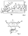
- FIG. 1 shows a device for reading a storage phosphor layer 1.
- a stimulation light beam 3 is generated, which is deflected by a deflecting element 4 so that it moves along a line 8 on the read out storage phosphor layer 1.
- the deflection element 4 has a reflective surface, in particular in the form of a mirror, which is set in oscillation by a drive device 5.
- an optical collecting device 6 for example a fiber optic bundle or a suitable mirror device
- an optical detector 7 preferably a photomultiplier, depending on the x-ray information stored therein. PMT
- the detector signal S is supplied to a processing device 16, in which image signal values B for individual pixels of the read-out X-ray image are derived. If the read-out line 8 is to be composed, for example, of 1000 pixels, then corresponding image signal values B are derived from the detector signal S 1000 obtained when reading out the line 8.
- a transport device By transporting the storage phosphor layer 1 in the transport direction T by means of a transport device (not shown), a successive readout of individual lines 8 of the storage phosphor layer 1 is achieved and thus a two-dimensional X-ray image composed of individual pixels each having an associated image signal value B is obtained. If the number of lines 8 read out in the transport direction T is, for example, 1500, then a total of 1500 by 1000 pixels each having an associated image signal value B are obtained with 1000 pixels per line 8 for the X-ray image read.
- the detector signal S is first filtered by a low-pass filter 12, wherein higher-frequency components of the detector signal S, in particular noise components, are eliminated.
- the filtered detector signal S is then fed to an analog-to-digital converter 13 and sampled there at a sampling frequency f, a detector signal D being obtained in each digital unit in each sampling operation.
- the sampling of the detector signal S in the analog-to-digital converter 13 is preferably carried out according to the so-called sample-and-hold principle, according to which the respective current analog signal height of the present at a sampling time at the analog-to-digital converter 13 detector signal S is held during scanning and in a corresponding digital detector signal value D is converted.
- the binding signal values B are calculated in a control unit 15 from the detector signal values D.
- the device shown further comprises two sensors 10 and 11, which are arranged on both sides of the storage phosphor layer 1 in such a way that the deflected stimulation light beam 3 'can impinge on it before or after it sweeps over the storage phosphor layer 1 along the line 8 or has crossed over. If the stimulation light beam 3 is deflected with the deflecting element 4 in the direction of the line 8, then this passes before the actual scanning of the line 8, first the first sensor 10 and then the second sensor 11. The light of the deflected stimulation light beam 3 'is thereby of the two photosensitive Sensors 10 and 11 detected and converted into corresponding electrical signals P (t1) and P (t2) at the times t1 and t2 and forwarded to the control unit 15 of the processing device 16.
- the control unit 15 is connected to the drive means 5 for driving the deflection element 4 and controls this in such a way that the deflection element 4 is driven by output of output energy from the drive means 5 only if or after the deflected stimulation light beam 3 'a certain direction and / or position.
- the deflected stimulation light beam 3 passeses over at least one of the two sensors 10 and 11, whereupon it sends an electrical pulse P to the control unit 15, which controls the drive device 5, if necessary after a predefinable time delay, in such a way that it intermittently Drive energy, in particular in the form of a drive energy pulse, outputs to the oscillating deflection element 4 and thereby maintains its oscillation, preferably in the region of a resonance frequency of the deflection element 4. This will be explained in more detail below.
- FIG. 2 shows a first example of a use of a deflecting element 4 in a side view.
- the corresponding deflection in plan view shows FIG. 3 ,
- the deflection element 4 has a reflective surface, which is attached via strip-shaped extensions 18 to a housing 9.
- the strip-shaped extensions 18 are preferably formed integrally with the reflective surface of the deflector 4, but can also be made separately from this and then connected to this.
- the strip-shaped extensions 18 represent a torsion spring, by means of which, upon deflection of the deflecting element 4 about an axis 17 extending along the extensions 18, a restoring force is generated which deflects the deflecting element 4 in the opposite direction, etc. In this way, the deflecting element 4 excited to an oscillation about the axis 17.
- the deflection of the deflecting element 4 is preferably carried out by an electromagnet 5, which generates a magnetic field by applying an electrical voltage and the associated current flow, the on a located on the deflector 4 befindliches magnetic element 4 'acts.
- an electromagnet 5 which generates a magnetic field by applying an electrical voltage and the associated current flow, the on a located on the deflector 4 befindliches magnetic element 4 'acts.
- the electromagnet 5 Depending on the material of the magnetic element 4 'this can both be attracted by the electromagnet 5 and repelled or only be attracted.
- the former is the case when the magnetic element has permanent magnetic substances.
- the latter is the case when using a ferromagnetic material whose magnetization is not permanently maintained.
- an optical device 20 a so-called.
- Postscan optics provided by which the deflected stimulation light beam 3 'is focused on the one hand on the storage phosphor layer 1 and on the other hand its radial movement in a linear movement along the line 8 is converted to the storage phosphor layer 1.
- a so-called variofocus can also be used, which is arranged between the laser 2 and the deflection element 4 (so-called prescan optics) and forms the laser beam 3 in such a way that, after being deflected by the deflection element 4 also a linear movement along the line 8 on the storage phosphor layer 1 is obtained.
- a postscan optics can then be omitted.
- FIG. 4 shows a plan view of a second example of a deflection element 4, which in contrast to the in FIG. 3 shown example can be excited not only by means of an electromagnet 5, but by means of two electromagnets 5 and the corresponding magnetic elements 4 'on the underside of the deflector 4 to oscillations about the axis 17.
- the two electromagnets 5 are preferably controlled such that an electromagnet 5 abuts the corresponding magnetic element 4 'on one side of the deflecting element 4 and the other electromagnet 5 attracts the corresponding magnetic element 4' on the other side of the deflecting element 4.
- the statements in connection with the Figures 2 and 3 corresponding.
- FIG. 5 is the time course of signals or states of the individual components of the device (see Fig. 1 ), namely the first sensor 10, the second sensor 11, the laser 2, the detector 7 and the electromagnet 5 on the deflection element 4.
- the illustrated course of the respective state of the laser 2, the detector 7 and the electromagnet 5 is in this case in such a way that the laser 2, detector 7 or electromagnet 5 is active and generates stimulation light, detects emission light or emits drive energy if a course different from the zero line is shown.
- the deflected stimulation light beam 3 'moving in the direction V sweeps over the sensor 10 at time t1, whereupon the sensor 10 sends a corresponding sensor signal P (t1) to the sensor Control unit 15 sends.
- This sensor signal is also referred to as the Begin of Line (BOL) signal.
- the emission light excited by the deflected stimulation light beam 3' is detected by the detector 7.
- the stimulation light beam 3 ' After passing through the line 8 of the storage phosphor layer 1, the stimulation light beam 3 'finally leaves the stimulation light beam 3' Storage phosphor layer 1 and passes over the second sensor 11 at time t2, whereupon this also generates a corresponding sensor signal P (t2).
- This sensor signal is also referred to as end of line (EOL) signal.
- the deflecting element 4 Due to the oscillatory movement of the deflecting element 4, the latter, after its maximum deflection, now performs a backward movement, in which the deflected stimulation light beam 3 'moving in the backward direction R (so-called retrace phase) sweeps over the second sensor 11 again at a time t3, whereupon the latter in turn sends a corresponding sensor signal to the control unit 15. This then turns off the laser 2 and causes the electromagnet 5 to generate a magnetic field, which is transmitted to the oscillating deflection 4 drive energy.
- the transmission of the drive energy takes place here only during a certain period of time Ta and during the return of the deflection 4 or during the imaginary return of the deflected (switched off) stimulation light beam 3 'in the direction R.
- the time period Ta of the excitation of the deflection 4 is preferably shorter than half of the period T of a complete oscillatory movement, ie a whole reciprocating movement, of the deflection element 4th
- FIG. 6 shows the course of the amplitude A of the oscillating deflection element, ie its deflection, over time t.
- T denotes the period of a complete oscillation of the deflecting element 4.
- the preferred period Ta of the output of drive energy to the deflecting element 4 is, as in FIG. 6 can be seen, shorter than half the period T / 2 of the oscillation and begins to run only at a time when the maximum deflection of the deflector 4 is already exceeded. The time of this maximum deflection is exactly in the middle between the two in FIG. 5 Plotted times t2 and t3.
- the timing of the period Ta for the excitation of the deflector 4 is achieved that is supplied to the deflector 4 only during movement in a direction of travel drive energy, even if the frequency of the oscillation of the deflection 4 temporarily changes slightly , in particular slightly larger, resulting in a temporary shortening of the current period T result.
- the (switched off) stimulation light beam 3 On its imaginary path in the retrace phase in the direction R over the storage phosphor layer 1, the (switched off) stimulation light beam 3 'leaves the storage phosphor layer 1 and reaches at time t4 the first sensor 11, whose imaginary sensor signal at time t4 in FIG Fig. 6 is drawn.
- the laser 2 After reversing the direction of the oscillating deflection element 4, the laser 2 is switched on again and the deflected stimulation light beam 3 'sweeps over the first sensor 10 again at a time t5, which generates a corresponding start of line signal (BOL).
- BOL start of line signal
- a sensor preferably in the form of a coil, to provide, which can detect the current position of the deflector 4.
- the transducer provides a corresponding pick-up signal when the oscillating deflector 4 changes position.
- one of the two electromagnets 5 in the in Fig. 4 be shown example for the delivery of drive energy, while the second electromagnet 5 takes over the function of the transducer, wherein the corresponding magnetic element 4 'of this electromagnet 5 is formed permanent magnetic.
- a relative movement between the element 4 'and the coil of the electromagnet 5 during the oscillation of the deflection 4 then induces in the coil a voltage that can be evaluated as a pickup signal, in particular, for example, the passage of a reversal point can be detected.
- the delivery of drive energy to the deflection element can then be controlled, in particular triggered.
- the delivery of drive energy can also take place in the trace phase.
- a delivery of the drive energy to the deflection element 4 can take place both in the trace and in the retrace phase.
- no so-called ballistic scanning during the detection of the emission light is then given, and crosstalk of the drive pulse to the electronics during data acquisition can not be ruled out.
- the advantage is achieved that due to the respective smaller amount of drive energy per unit time each shorter drive pulses can be selected, which ensures a reliable drive of the deflection even at higher frequency oscillations, as already explained above.
- the shape of the drive pulses in the delivery of the drive energy may have the shape of a rectangle, as in Fig. 5 with respect to the electromagnet 5 shown.
- the shape of the drive pulses may also have a shape deviating from the rectangular shape, in particular any desired shape. In this way, for example, the occurrence of electromagnetic interference can be greatly reduced or even prevented, which significantly improves the electromagnetic compatibility (EMC) of the device.
- EMC electromagnetic compatibility
- the drive pulse may also have a pulse duration Ta longer than half a period T / 2 of the oscillation.
- An associated "braking effect" on the deflecting element 4 may be desirable and correspondingly advantageous under certain circumstances.
- the polarity of the drive pulse may change, the polarity change preferably, but not necessarily, being performed at a reversal point of the oscillation. Also, by doing so, an effective driving of the vibration can be realized.
- BOL or EOL sensors 10 and 11 can also own photodiodes or others position and time-sensitive sensors may be provided, which need not necessarily lie in the plane or in the curvature of the storage phosphor layer 1.
- a sensor in the vicinity of the rest position of the deflection element 4 may be advantageous, but viewed from the deflection element 4, behind the plane of FIG Storage phosphor layer 1 is located so that it is used only before retraction of the storage phosphor layer 1 for detecting the deflected stimulation light beam 3 ', while it is concealed during the actual read when retracted storage phosphor layer 1 of this.
- FIG. 7 shows a second example of a use of the deflector 4 in a side view.
- the storage phosphor layer 1 is not flat, but curved.
- the course of the curvature of the storage phosphor layer 1 substantially corresponds to the curvature of a portion of a cylindrical surface whose axis is parallel to the direction of transport T (see FIG. Fig. 1 ) is aligned.
- Such a curvature has compared to the reading of a planar storage phosphor layer 1 (see FIG. 2 ) has the advantage that special optical devices (see Postscan Optics 20 in Fig. 2 ) between the deflection element 4 and the storage phosphor layer 1 can be dispensed with, which simplifies the structure of the device.
Landscapes
- Physics & Mathematics (AREA)
- General Physics & Mathematics (AREA)
- Engineering & Computer Science (AREA)
- Multimedia (AREA)
- Signal Processing (AREA)
- Optics & Photonics (AREA)
- Health & Medical Sciences (AREA)
- Life Sciences & Earth Sciences (AREA)
- High Energy & Nuclear Physics (AREA)
- Molecular Biology (AREA)
- Spectroscopy & Molecular Physics (AREA)
- Electromagnetism (AREA)
- Facsimile Scanning Arrangements (AREA)
- Radiography Using Non-Light Waves (AREA)
- Investigating, Analyzing Materials By Fluorescence Or Luminescence (AREA)
Claims (9)
- Dispositif de lecture d'informations radiographiques stockées dans une couche luminescente à mémoire (1), comprenant- une source lumineuse (2) servant à générer un faisceau de lumière de stimulation (3) qui est capable de stimuler la couche luminescente à mémoire (1) afin de la faire émettre de la lumière d'émission,- un élément déflecteur (4) servant à dévier le faisceau de lumière de stimulation (3) de façon à ce que le faisceau de lumière de stimulation dévié (3') se déplace en travers de la couche luminescente à mémoire (1),- un équipement d'entraînement (5) servant à entrainer l'élément déflecteur (4), ledit élément déflecteur (4) comprenant une zone réfléchissante mise en mouvement oscillant par l'équipement d'entraînement (5), et- un détecteur (7) servant à détecter de la lumière d'émission émise par la couche luminescente à mémoire (1) lorsque le faisceau de lumière de stimulation dévié (3') se déplace dans un premier sens de mouvement (V) en travers de la couche luminescente à mémoire (1) et que l'élément déflecteur (4) se déplace dans un premier sens,
caractérisé en ce que
ledit détecteur (7) est conçu ou ledit dispositif est contrôlé de façon à ce que le détecteur (7) ne détecte pas de lumière d'émission lorsque le faisceau de lumière de stimulation dévié (3') se déplace dans un deuxième sens de mouvement (R) opposé au premier sens de mouvement (V) et que l'élément déflecteur (4) se déplace dans un deuxième sens opposé au premier sens,
au moins un élément de détection (10, 11) est prévu pour détecter la position du faisceau de lumière de stimulation dévié (3') et une unité de contrôle (15) est prévue pour contrôler l'équipement d'entraînement (5) de façon à ce que- de l'énergie d'entraînement soit transmise, sous forme d'impulsions, à l'élément déflecteur (4) en fonction de la position détectée du faisceau de lumière de stimulation dévié (3'), ladite transmission d'énergie d'entraînement à l'élément déflecteur (4) étant déclenchée lorsque le faisceau de lumière de stimulation dévié (3') se déplace dans le deuxième sens de mouvement (R), et- ladite transmission d'énergie d'entraînement à l'élément déflecteur (4) ne soit déclenchée que lorsque le faisceau de lumière de stimulation dévié (3') se déplace dans le deuxième sens de mouvement (R) et que l'élément déflecteur (4) se déplace dans le deuxième sens. - Dispositif selon la revendication 1, caractérisé en ce que l'équipement d'entraînement (5) est conçu de façon à ce que la transmission d'énergie d'entraînement à l'élément déflecteur (4) soit déclenchée, à l'issue d'un délai d'attente prédéfini, par le faisceau de lumière de stimulation dévié (3') après son passage devant ledit au moins un élément de détection (11).
- Dispositif selon l'une quelconque des revendications précédentes, comprenant au moins un capteur servant à détecter la position de l'élément déflecteur (4).
- Dispositif selon l'une quelconque des revendications précédentes, caractérisé en ce que l'élément déflecteur (4) comprend un élément magnétique (4') et que l'équipement d'entraînement (5) comprend une unité électromagnétique pouvant interagir avec l'élément magnétique (4') afin de transmettre de l'énergie d'entraînement à l'élément déflecteur (4).
- Dispositif selon l'une quelconque des revendications précédentes, caractérisé en ce que la zone réfléchissante de l'élément déflecteur (4) peut être stimulée par l'équipement d'entraînement (5) afin de la faire osciller autour d'un axe (17) qui s'étend, de préférence, parallèlement à la zone à miroirs.
- Dispositif selon la revendication 5, caractérisé en ce que la zone réfléchissante a une fréquence de résonance et que l'équipement d'entraînement (5) est configuré de façon à ce qu'il entraîne la zone réfléchissante de façon à la faire osciller à sa fréquence de résonance.
- Dispositif selon l'une quelconque des revendications précédentes, caractérisé en ce que l'élément déflecteur (4) oscille avec une période (T) et que les impulsions ont une durée d'impulsion (Ta) inférieure à la demi-période (T/2).
- Dispositif selon l'une quelconque des revendications précédentes, comprenant un équipement de transport pouvant courber la couche luminescente à mémoire (1) au moins pendant la lecture.
- Procédé de lecture d'informations radiographiques stockées dans une couche luminescente à mémoire (1), caractérisé en ce que- un faisceau de lumière de stimulation (3) qui est capable de stimuler la couche luminescente à mémoire (1) afin de la faire émettre de la lumière d'émission, est dévié par un élément déflecteur (4) pour se déplacer en travers de la couche luminescente à mémoire (1),- l'élément déflecteur (4) comprend une zone réfléchissante mise en mouvement oscillant par l'équipement d'entraînement (5), et- la lumière d'émission émise par la couche luminescente à mémoire (1) est captée lorsque le faisceau de lumière de stimulation dévié (3') se déplace dans un premier sens de mouvement (V) en travers de la couche luminescente à mémoire (1) et que l'élément déflecteur (4) se déplace dans un premier sens, caractérisé en ce que- aucune lumière d'émission n'est captée lorsque le faisceau de lumière de stimulation dévié (3') se déplace dans un deuxième sens de mouvement (R) opposé au premier sens de mouvement (V) et que l'élément déflecteur (4) se déplace dans un deuxième sens opposé au premier sens,- la position du faisceau de lumière de stimulation dévié (3') est détectée par au moins un élément de détection (10, 11) et que l'équipement d'entraînement (5) transmet de l'énergie d'entraînement, sous forme d'impulsions, à l'élément déflecteur (4) en fonction de la position détectée du faisceau de lumière de stimulation dévié (3'), où- ladite transmission d'énergie d'entraînement à l'élément déflecteur (4) est déclenchée lorsque le faisceau de lumière de stimulation dévié (3') se déplace dans le deuxième sens de mouvement (R), et- ladite transmission d'énergie d'entraînement à l'élément déflecteur (4) ne soit déclenchée que lorsque le faisceau de lumière de stimulation dévié (3') se déplace dans le deuxième sens de mouvement (R) et que l'élément déflecteur (4) se déplace dans le deuxième sens.
Priority Applications (5)
| Application Number | Priority Date | Filing Date | Title |
|---|---|---|---|
| EP10015266.9A EP2461184B1 (fr) | 2010-12-03 | 2010-12-03 | Dispositif et procédé destinés à l'extraction d'informations radiographiques stockées sur un disque fluorescent de mémoire |
| PCT/EP2011/004757 WO2012072158A1 (fr) | 2010-12-03 | 2011-09-22 | Dispositif et procédé destinés à la lecture de données radiographiques enregistrées dans une couche de mémoire en matière luminescente |
| EP11761514.6A EP2646847B1 (fr) | 2010-12-03 | 2011-09-22 | Dispositif et procédé destinés à la lecture de données radiographiques enregistrées dans une couche de mémoire en matière luminescente |
| US13/989,430 US9551797B2 (en) | 2010-12-03 | 2011-09-22 | Device and method for reading out X-ray information stored in a fluorescent storage layer |
| CN201180058265.1A CN103229074B (zh) | 2010-12-03 | 2011-09-22 | 用于读取在存储荧光层中所存储的x射线信息的设备和方法 |
Applications Claiming Priority (1)
| Application Number | Priority Date | Filing Date | Title |
|---|---|---|---|
| EP10015266.9A EP2461184B1 (fr) | 2010-12-03 | 2010-12-03 | Dispositif et procédé destinés à l'extraction d'informations radiographiques stockées sur un disque fluorescent de mémoire |
Publications (2)
| Publication Number | Publication Date |
|---|---|
| EP2461184A1 EP2461184A1 (fr) | 2012-06-06 |
| EP2461184B1 true EP2461184B1 (fr) | 2015-07-08 |
Family
ID=43640244
Family Applications (2)
| Application Number | Title | Priority Date | Filing Date |
|---|---|---|---|
| EP10015266.9A Not-in-force EP2461184B1 (fr) | 2010-12-03 | 2010-12-03 | Dispositif et procédé destinés à l'extraction d'informations radiographiques stockées sur un disque fluorescent de mémoire |
| EP11761514.6A Not-in-force EP2646847B1 (fr) | 2010-12-03 | 2011-09-22 | Dispositif et procédé destinés à la lecture de données radiographiques enregistrées dans une couche de mémoire en matière luminescente |
Family Applications After (1)
| Application Number | Title | Priority Date | Filing Date |
|---|---|---|---|
| EP11761514.6A Not-in-force EP2646847B1 (fr) | 2010-12-03 | 2011-09-22 | Dispositif et procédé destinés à la lecture de données radiographiques enregistrées dans une couche de mémoire en matière luminescente |
Country Status (4)
| Country | Link |
|---|---|
| US (1) | US9551797B2 (fr) |
| EP (2) | EP2461184B1 (fr) |
| CN (1) | CN103229074B (fr) |
| WO (1) | WO2012072158A1 (fr) |
Families Citing this family (6)
| Publication number | Priority date | Publication date | Assignee | Title |
|---|---|---|---|---|
| EP2461184B1 (fr) | 2010-12-03 | 2015-07-08 | Agfa HealthCare N.V. | Dispositif et procédé destinés à l'extraction d'informations radiographiques stockées sur un disque fluorescent de mémoire |
| EP2527874B1 (fr) | 2011-05-26 | 2017-10-11 | Agfa HealthCare NV | Système, dispositif et procédé destinés à l'extraction d'informations radiographiques stockées sur un disque fluorescent de mémoire |
| EP2879001B1 (fr) * | 2013-11-27 | 2018-05-23 | Agfa HealthCare N.V. | Appareil et procédé de lecture de plaques de phosphore de stockage |
| EP2921881B1 (fr) * | 2014-03-18 | 2018-11-28 | Agfa Nv | Ensemble plaque de stockage phosphoreuse, cassette de radiographie et système de lecture de telles plaques |
| EP2930537A1 (fr) * | 2014-04-08 | 2015-10-14 | Agfa HealthCare N.V. | Appareil pour lire des informations radiographiques stockées dans une couche de phosphore de stockage |
| DE102016200503A1 (de) * | 2016-01-16 | 2017-07-20 | Robert Bosch Gmbh | Vorrichtung und Verfahren zum Erzeugen von Licht mittels eines Leuchtstoffs |
Citations (1)
| Publication number | Priority date | Publication date | Assignee | Title |
|---|---|---|---|---|
| US20050017207A1 (en) * | 2003-07-24 | 2005-01-27 | Eastman Kodak Company | Storage phosphor erase |
Family Cites Families (40)
| Publication number | Priority date | Publication date | Assignee | Title |
|---|---|---|---|---|
| US4856858A (en) * | 1987-01-30 | 1989-08-15 | Citizen Watch Co., Ltd. | Optical scanner |
| US5187364A (en) * | 1989-03-22 | 1993-02-16 | National Research Council Of Canada/Conseil National De Recherches Du Canada | Scanning device with waveform generator optimizer |
| US5231575A (en) * | 1989-10-20 | 1993-07-27 | Fuji Photo Film Co., Ltd. | Image read-out apparatus |
| US5691535A (en) * | 1996-02-08 | 1997-11-25 | Eastman Kodak Company | Ganged laser scanning system which corrects beam alignment along a bow-tie path |
| US6239448B1 (en) * | 1998-04-22 | 2001-05-29 | Fuji Photo Film Co., Ltd. | Radiation image read-out method and apparatus |
| DE19962775C1 (de) | 1999-12-23 | 2001-03-15 | Agfa Gevaert Ag | Vorrichtung zum Auslesen von in einer Speicherschicht abgespeicherten Informationen und Röntgenkassette |
| JP3740381B2 (ja) * | 2001-04-25 | 2006-02-01 | 三菱電機株式会社 | 電磁アクチュエータ |
| DE50106802D1 (de) | 2001-09-27 | 2005-08-25 | Agfa Gevaert Ag | Abbildungsvorrichtung zum Abbilden eines länglichen Gegenstandes |
| DE50306024D1 (de) | 2003-03-28 | 2007-02-01 | Agfa Gevaert Healthcare Gmbh | Vorrichtung zum Erfassen von in einer Phosphorschicht enthaltenen Bildinformationen |
| EP1462826B1 (fr) | 2003-03-28 | 2007-02-07 | Agfa-Gevaert HealthCare GmbH | Dispositif pour la lecture d'information d'image à partir d'une couche de phosphore |
| DE50310317D1 (de) | 2003-05-21 | 2008-09-25 | Agfa Gevaert Healthcare Gmbh | Vorrichtung zum Erfassen von in einer Phosphorschicht enthaltenen Informationen |
| EP1482721A1 (fr) | 2003-05-26 | 2004-12-01 | Agfa-Gevaert AG | Dispositif de saisie d'informations contenues dans une couche de phosphore |
| EP1482328B1 (fr) | 2003-05-26 | 2006-10-18 | Agfa-Gevaert HealthCare GmbH | Dispositif de détection d'informations dans une couche de matière luminéscente |
| US6965177B2 (en) * | 2003-06-18 | 2005-11-15 | Texas Instruments Incorporated | Pulse drive of resonant MEMS devices |
| ATE367598T1 (de) | 2003-08-01 | 2007-08-15 | Agfa Gevaert Healthcare Gmbh | Vorrichtung zum auslesen von in einer speicherschicht gespeicherten information |
| US7045805B2 (en) * | 2003-08-08 | 2006-05-16 | Noa Katz | Apparatus and method for supporting and shaping a photo-stimulable phosphor plate |
| EP1528412B1 (fr) | 2003-10-31 | 2011-05-11 | Agfa-Gevaert HealthCare GmbH | Méthode et système de lecture pour substance luminescente photostimulable |
| ATE442595T1 (de) | 2004-07-29 | 2009-09-15 | Agfa Gevaert Healthcare Gmbh | Verfahren zum auslesen von in einer phosphorschicht gespeicherten informationen |
| EP1653481A1 (fr) | 2004-10-29 | 2006-05-03 | Agfa-Gevaert HealthCare GmbH | Plaque radiographique de phosphore et dispositif pour lire des informations à rayons X |
| ATE535824T1 (de) | 2005-02-15 | 2011-12-15 | Agfa Gevaert Healthcare Gmbh | Auslesevorrichtung und verfahren zum auslesen von in speicherleuchtstoffschichten gespeicherten röntgenaufnahmen |
| EP1691216B1 (fr) | 2005-02-15 | 2013-07-10 | Agfa-Gevaert HealthCare GmbH | Système radiographique et méthode d'enregistrement des radiographies dans des feuilles photostimulables |
| EP1691215B1 (fr) | 2005-02-15 | 2012-11-28 | Agfa-Gevaert HealthCare GmbH | Procédé et appareil pour lire des vues radiographiques enregistrées dans des écrans luminescents |
| ATE462151T1 (de) | 2005-12-29 | 2010-04-15 | Agfa Gevaert Healthcare Gmbh | Vorrichtung zum auslesen von in einer speicherleuchtstoffschicht abgespeicherten röntgeninformationen sowie radiografiemodul |
| ATE461464T1 (de) | 2005-12-29 | 2010-04-15 | Agfa Gevaert Healthcare Gmbh | Vorrichtung zum auslesen von in einer speicherleuchtstoffschicht abgespeicherten röntgeninformationen sowie radiografiemodul |
| US7557972B2 (en) * | 2006-06-07 | 2009-07-07 | Canon Kabushiki Kaisha | Oscillator device, optical deflector and optical instrument using the same |
| JP2008051698A (ja) * | 2006-08-25 | 2008-03-06 | Yokogawa Electric Corp | 双方向光モジュールおよびこれを用いた光パルス試験器 |
| DE502006005121D1 (de) * | 2006-08-29 | 2009-11-26 | Agfa Healthcare Nv | Verfahren und Vorrichtung zum Auslesen von in einer Speicherleuchtstoffplatte gespeicherten Röntgeninformationen |
| EP1895327B1 (fr) | 2006-08-31 | 2009-11-11 | Agfa HealthCare NV | Effacement d'une couche d'enregistrement luminescente |
| ATE474238T1 (de) | 2006-08-31 | 2010-07-15 | Agfa Healthcare Nv | Vorrichtung zum löschen einer speicherleuchtstoffschicht |
| US7800640B2 (en) * | 2006-08-31 | 2010-09-21 | Lexmark International, Inc. | Obtaining pressure of an operating environment of a bi-directionally scanning electrophotographic device for implementing corrections per pressure |
| ATE462986T1 (de) | 2006-08-31 | 2010-04-15 | Agfa Healthcare Nv | Löschen einer speicherleuchtstoffschicht |
| EP1936405B1 (fr) | 2006-12-21 | 2010-07-21 | Agfa HealthCare NV | Dispositif et procédé destinés à effacer une couche d'enregistrement luminescente et système avec un tel dispositif et un détecteur |
| JP5072688B2 (ja) * | 2008-04-02 | 2012-11-14 | キヤノン株式会社 | 走査型撮像装置 |
| DK2746719T3 (en) * | 2008-07-24 | 2017-12-11 | Massachusetts Inst Technology | SYSTEMS AND PROCEDURES FOR IMAGE IMPACT WITH USE OF ABSORPTION |
| EP2228668A1 (fr) | 2009-03-09 | 2010-09-15 | Agfa HealthCare | Procédé de suppression de l'effet de rémanence d'une image de rayonnement lue en dehors d'un écran au phosphore photostimulable |
| KR101019714B1 (ko) * | 2009-04-01 | 2011-03-07 | 쓰리디이미징앤시뮬레이션즈(주) | 디지털 엑스레이 영상 획득장치 |
| EP2290404B1 (fr) | 2009-08-31 | 2012-08-29 | Agfa HealthCare NV | Procédé et appareil de lecture et d'effacage de l'effet d'un rayonnnement X sur un écran photostimulable |
| WO2011091093A1 (fr) * | 2010-01-22 | 2011-07-28 | Cambridge Technology, Inc. | Dispositifs de balayage résonnants à rubans tendus, à angle de balayage important, à faible oscillation, présentant des coefficients de dilatation thermique adaptés et des miroirs interchangeables |
| EP2461184B1 (fr) | 2010-12-03 | 2015-07-08 | Agfa HealthCare N.V. | Dispositif et procédé destinés à l'extraction d'informations radiographiques stockées sur un disque fluorescent de mémoire |
| EP2527874B1 (fr) | 2011-05-26 | 2017-10-11 | Agfa HealthCare NV | Système, dispositif et procédé destinés à l'extraction d'informations radiographiques stockées sur un disque fluorescent de mémoire |
-
2010
- 2010-12-03 EP EP10015266.9A patent/EP2461184B1/fr not_active Not-in-force
-
2011
- 2011-09-22 CN CN201180058265.1A patent/CN103229074B/zh not_active Expired - Fee Related
- 2011-09-22 EP EP11761514.6A patent/EP2646847B1/fr not_active Not-in-force
- 2011-09-22 US US13/989,430 patent/US9551797B2/en not_active Expired - Fee Related
- 2011-09-22 WO PCT/EP2011/004757 patent/WO2012072158A1/fr not_active Ceased
Patent Citations (1)
| Publication number | Priority date | Publication date | Assignee | Title |
|---|---|---|---|---|
| US20050017207A1 (en) * | 2003-07-24 | 2005-01-27 | Eastman Kodak Company | Storage phosphor erase |
Also Published As
| Publication number | Publication date |
|---|---|
| CN103229074B (zh) | 2017-03-15 |
| EP2461184A1 (fr) | 2012-06-06 |
| WO2012072158A1 (fr) | 2012-06-07 |
| EP2646847A1 (fr) | 2013-10-09 |
| US20130234048A1 (en) | 2013-09-12 |
| EP2646847B1 (fr) | 2018-12-19 |
| US9551797B2 (en) | 2017-01-24 |
| CN103229074A (zh) | 2013-07-31 |
Similar Documents
| Publication | Publication Date | Title |
|---|---|---|
| EP2461184B1 (fr) | Dispositif et procédé destinés à l'extraction d'informations radiographiques stockées sur un disque fluorescent de mémoire | |
| DE69028597T2 (de) | Resonanzabtaster | |
| DE69703213T2 (de) | Vorrichtung und Verfahren zur Fokusierung eines Laserstrahls für optische Codes | |
| EP2527874B1 (fr) | Système, dispositif et procédé destinés à l'extraction d'informations radiographiques stockées sur un disque fluorescent de mémoire | |
| DE102017002235A1 (de) | LIDAR-System mit flexiblen Scanparametern | |
| DE19882768B3 (de) | Zweiter Ordnung differenzierender Signalprozessor für einen Strichkodescanner sowie Signalverarbeitungsverfahren zum Verwenden von Strichkodescannern | |
| EP1424569A2 (fr) | Dispositif pour la lecture d'une information stockée dans un support au phosphore, et coffret de radiographie | |
| DE69124052T2 (de) | Laserstrahlstreifencodeleser | |
| DE3006546A1 (de) | Lichtstrahl-abtastvorrichtung | |
| EP1691216B1 (fr) | Système radiographique et méthode d'enregistrement des radiographies dans des feuilles photostimulables | |
| DE2365916C2 (de) | Vorrichtung zum zeilenweisen Aufzeichnen von Informationen in einem elektrischen Signal auf ein abgetastetes lichtempfindliches Medium | |
| DE19813798B4 (de) | Schaltung zum Erzeugen eines Synchronisationssignals für eine optische Abtasteinrichtung | |
| EP1691217B1 (fr) | Procédé et appareil pour lire des vues radiographiques enregistrées dans un écran luminescent | |
| EP1691215B1 (fr) | Procédé et appareil pour lire des vues radiographiques enregistrées dans des écrans luminescents | |
| DE3128469C2 (de) | Verfahren und Vorrichtung zum Abtasten von Strahlungsenergie | |
| DE10205207B4 (de) | Anordnung und Verfahren zur Messung an einem resonanten Schwinger und zu seiner Steuerung | |
| DE102016122194A1 (de) | Verfahren zum Betreiben eines optoelektronischen Sensors eines Kraftfahrzeugs mit variabler Ansteuerung einer Lichtquelle, optoelektronischer Sensor, Fahrerassistenzsystem sowie Kraftfahrzeug | |
| EP2290404B1 (fr) | Procédé et appareil de lecture et d'effacage de l'effet d'un rayonnnement X sur un écran photostimulable | |
| DE102007008009B3 (de) | Verfahren zur Ansteuerung eines Scanmikroskops | |
| WO2002015561A1 (fr) | Procede d'elimination electronique de la distorsion d'images dans des dispositifs de balayage par laser | |
| EP1621899B1 (fr) | Procédé pour lire les informations contenues dans une couche phosphore | |
| EP1895324B1 (fr) | Procédé et dispositif destinés à l'extraction d'informations radiographiques stockées sur un disque fluorescent de mémoire | |
| EP1612582B1 (fr) | Dispositif et méthode pour la lecture d'information d'image à partir d'une couche de phosphore | |
| EP2793053A1 (fr) | Procédé et dispositifs destinés à la lecture d'informations radiographiques stockées sur une couche fluorescente de mémoire | |
| DE102020111786B4 (de) | Verfahren und Mikroskopvorrichtung für die beschleunigte Mikroskopie großer Proben sowie Datenträger |
Legal Events
| Date | Code | Title | Description |
|---|---|---|---|
| PUAI | Public reference made under article 153(3) epc to a published international application that has entered the european phase |
Free format text: ORIGINAL CODE: 0009012 |
|
| AK | Designated contracting states |
Kind code of ref document: A1 Designated state(s): AL AT BE BG CH CY CZ DE DK EE ES FI FR GB GR HR HU IE IS IT LI LT LU LV MC MK MT NL NO PL PT RO RS SE SI SK SM TR |
|
| AX | Request for extension of the european patent |
Extension state: BA ME |
|
| 17P | Request for examination filed |
Effective date: 20121206 |
|
| 17Q | First examination report despatched |
Effective date: 20130123 |
|
| GRAP | Despatch of communication of intention to grant a patent |
Free format text: ORIGINAL CODE: EPIDOSNIGR1 |
|
| INTG | Intention to grant announced |
Effective date: 20150327 |
|
| RIN1 | Information on inventor provided before grant (corrected) |
Inventor name: REISER, GEORG Inventor name: MAIR, STEPHAN |
|
| GRAS | Grant fee paid |
Free format text: ORIGINAL CODE: EPIDOSNIGR3 |
|
| GRAA | (expected) grant |
Free format text: ORIGINAL CODE: 0009210 |
|
| RIN1 | Information on inventor provided before grant (corrected) |
Inventor name: MAIR, STEPHAN Inventor name: REISER, GEORG |
|
| AK | Designated contracting states |
Kind code of ref document: B1 Designated state(s): AL AT BE BG CH CY CZ DE DK EE ES FI FR GB GR HR HU IE IS IT LI LT LU LV MC MK MT NL NO PL PT RO RS SE SI SK SM TR |
|
| REG | Reference to a national code |
Ref country code: GB Ref legal event code: FG4D Free format text: NOT ENGLISH |
|
| REG | Reference to a national code |
Ref country code: AT Ref legal event code: REF Ref document number: 735831 Country of ref document: AT Kind code of ref document: T Effective date: 20150715 Ref country code: CH Ref legal event code: EP |
|
| REG | Reference to a national code |
Ref country code: IE Ref legal event code: FG4D Free format text: LANGUAGE OF EP DOCUMENT: GERMAN |
|
| REG | Reference to a national code |
Ref country code: DE Ref legal event code: R096 Ref document number: 502010009804 Country of ref document: DE |
|
| REG | Reference to a national code |
Ref country code: FR Ref legal event code: PLFP Year of fee payment: 6 |
|
| REG | Reference to a national code |
Ref country code: NL Ref legal event code: MP Effective date: 20150708 |
|
| REG | Reference to a national code |
Ref country code: LT Ref legal event code: MG4D |
|
| PG25 | Lapsed in a contracting state [announced via postgrant information from national office to epo] |
Ref country code: NO Free format text: LAPSE BECAUSE OF FAILURE TO SUBMIT A TRANSLATION OF THE DESCRIPTION OR TO PAY THE FEE WITHIN THE PRESCRIBED TIME-LIMIT Effective date: 20151008 Ref country code: GR Free format text: LAPSE BECAUSE OF FAILURE TO SUBMIT A TRANSLATION OF THE DESCRIPTION OR TO PAY THE FEE WITHIN THE PRESCRIBED TIME-LIMIT Effective date: 20151009 Ref country code: LT Free format text: LAPSE BECAUSE OF FAILURE TO SUBMIT A TRANSLATION OF THE DESCRIPTION OR TO PAY THE FEE WITHIN THE PRESCRIBED TIME-LIMIT Effective date: 20150708 Ref country code: LV Free format text: LAPSE BECAUSE OF FAILURE TO SUBMIT A TRANSLATION OF THE DESCRIPTION OR TO PAY THE FEE WITHIN THE PRESCRIBED TIME-LIMIT Effective date: 20150708 Ref country code: FI Free format text: LAPSE BECAUSE OF FAILURE TO SUBMIT A TRANSLATION OF THE DESCRIPTION OR TO PAY THE FEE WITHIN THE PRESCRIBED TIME-LIMIT Effective date: 20150708 |
|
| PG25 | Lapsed in a contracting state [announced via postgrant information from national office to epo] |
Ref country code: PT Free format text: LAPSE BECAUSE OF FAILURE TO SUBMIT A TRANSLATION OF THE DESCRIPTION OR TO PAY THE FEE WITHIN THE PRESCRIBED TIME-LIMIT Effective date: 20151109 Ref country code: IS Free format text: LAPSE BECAUSE OF FAILURE TO SUBMIT A TRANSLATION OF THE DESCRIPTION OR TO PAY THE FEE WITHIN THE PRESCRIBED TIME-LIMIT Effective date: 20151108 Ref country code: SE Free format text: LAPSE BECAUSE OF FAILURE TO SUBMIT A TRANSLATION OF THE DESCRIPTION OR TO PAY THE FEE WITHIN THE PRESCRIBED TIME-LIMIT Effective date: 20150708 Ref country code: HR Free format text: LAPSE BECAUSE OF FAILURE TO SUBMIT A TRANSLATION OF THE DESCRIPTION OR TO PAY THE FEE WITHIN THE PRESCRIBED TIME-LIMIT Effective date: 20150708 Ref country code: PL Free format text: LAPSE BECAUSE OF FAILURE TO SUBMIT A TRANSLATION OF THE DESCRIPTION OR TO PAY THE FEE WITHIN THE PRESCRIBED TIME-LIMIT Effective date: 20150708 Ref country code: ES Free format text: LAPSE BECAUSE OF FAILURE TO SUBMIT A TRANSLATION OF THE DESCRIPTION OR TO PAY THE FEE WITHIN THE PRESCRIBED TIME-LIMIT Effective date: 20150708 Ref country code: RS Free format text: LAPSE BECAUSE OF FAILURE TO SUBMIT A TRANSLATION OF THE DESCRIPTION OR TO PAY THE FEE WITHIN THE PRESCRIBED TIME-LIMIT Effective date: 20150708 |
|
| REG | Reference to a national code |
Ref country code: DE Ref legal event code: R097 Ref document number: 502010009804 Country of ref document: DE |
|
| PG25 | Lapsed in a contracting state [announced via postgrant information from national office to epo] |
Ref country code: SK Free format text: LAPSE BECAUSE OF FAILURE TO SUBMIT A TRANSLATION OF THE DESCRIPTION OR TO PAY THE FEE WITHIN THE PRESCRIBED TIME-LIMIT Effective date: 20150708 Ref country code: CZ Free format text: LAPSE BECAUSE OF FAILURE TO SUBMIT A TRANSLATION OF THE DESCRIPTION OR TO PAY THE FEE WITHIN THE PRESCRIBED TIME-LIMIT Effective date: 20150708 Ref country code: IT Free format text: LAPSE BECAUSE OF FAILURE TO SUBMIT A TRANSLATION OF THE DESCRIPTION OR TO PAY THE FEE WITHIN THE PRESCRIBED TIME-LIMIT Effective date: 20150708 Ref country code: DK Free format text: LAPSE BECAUSE OF FAILURE TO SUBMIT A TRANSLATION OF THE DESCRIPTION OR TO PAY THE FEE WITHIN THE PRESCRIBED TIME-LIMIT Effective date: 20150708 Ref country code: EE Free format text: LAPSE BECAUSE OF FAILURE TO SUBMIT A TRANSLATION OF THE DESCRIPTION OR TO PAY THE FEE WITHIN THE PRESCRIBED TIME-LIMIT Effective date: 20150708 |
|
| PLBE | No opposition filed within time limit |
Free format text: ORIGINAL CODE: 0009261 |
|
| STAA | Information on the status of an ep patent application or granted ep patent |
Free format text: STATUS: NO OPPOSITION FILED WITHIN TIME LIMIT |
|
| PG25 | Lapsed in a contracting state [announced via postgrant information from national office to epo] |
Ref country code: RO Free format text: LAPSE BECAUSE OF FAILURE TO SUBMIT A TRANSLATION OF THE DESCRIPTION OR TO PAY THE FEE WITHIN THE PRESCRIBED TIME-LIMIT Effective date: 20150708 Ref country code: BE Free format text: LAPSE BECAUSE OF NON-PAYMENT OF DUE FEES Effective date: 20151231 |
|
| 26N | No opposition filed |
Effective date: 20160411 |
|
| PG25 | Lapsed in a contracting state [announced via postgrant information from national office to epo] |
Ref country code: LU Free format text: LAPSE BECAUSE OF FAILURE TO SUBMIT A TRANSLATION OF THE DESCRIPTION OR TO PAY THE FEE WITHIN THE PRESCRIBED TIME-LIMIT Effective date: 20151203 Ref country code: MC Free format text: LAPSE BECAUSE OF FAILURE TO SUBMIT A TRANSLATION OF THE DESCRIPTION OR TO PAY THE FEE WITHIN THE PRESCRIBED TIME-LIMIT Effective date: 20150708 |
|
| REG | Reference to a national code |
Ref country code: CH Ref legal event code: PL |
|
| PG25 | Lapsed in a contracting state [announced via postgrant information from national office to epo] |
Ref country code: SI Free format text: LAPSE BECAUSE OF FAILURE TO SUBMIT A TRANSLATION OF THE DESCRIPTION OR TO PAY THE FEE WITHIN THE PRESCRIBED TIME-LIMIT Effective date: 20150708 |
|
| REG | Reference to a national code |
Ref country code: IE Ref legal event code: MM4A |
|
| PG25 | Lapsed in a contracting state [announced via postgrant information from national office to epo] |
Ref country code: IE Free format text: LAPSE BECAUSE OF NON-PAYMENT OF DUE FEES Effective date: 20151203 Ref country code: CH Free format text: LAPSE BECAUSE OF NON-PAYMENT OF DUE FEES Effective date: 20151231 Ref country code: LI Free format text: LAPSE BECAUSE OF NON-PAYMENT OF DUE FEES Effective date: 20151231 |
|
| REG | Reference to a national code |
Ref country code: FR Ref legal event code: PLFP Year of fee payment: 7 |
|
| REG | Reference to a national code |
Ref country code: AT Ref legal event code: MM01 Ref document number: 735831 Country of ref document: AT Kind code of ref document: T Effective date: 20151203 |
|
| PG25 | Lapsed in a contracting state [announced via postgrant information from national office to epo] |
Ref country code: AT Free format text: LAPSE BECAUSE OF NON-PAYMENT OF DUE FEES Effective date: 20151203 Ref country code: BG Free format text: LAPSE BECAUSE OF FAILURE TO SUBMIT A TRANSLATION OF THE DESCRIPTION OR TO PAY THE FEE WITHIN THE PRESCRIBED TIME-LIMIT Effective date: 20150708 Ref country code: HU Free format text: LAPSE BECAUSE OF FAILURE TO SUBMIT A TRANSLATION OF THE DESCRIPTION OR TO PAY THE FEE WITHIN THE PRESCRIBED TIME-LIMIT; INVALID AB INITIO Effective date: 20101203 Ref country code: SM Free format text: LAPSE BECAUSE OF FAILURE TO SUBMIT A TRANSLATION OF THE DESCRIPTION OR TO PAY THE FEE WITHIN THE PRESCRIBED TIME-LIMIT Effective date: 20150708 |
|
| PG25 | Lapsed in a contracting state [announced via postgrant information from national office to epo] |
Ref country code: NL Free format text: LAPSE BECAUSE OF FAILURE TO SUBMIT A TRANSLATION OF THE DESCRIPTION OR TO PAY THE FEE WITHIN THE PRESCRIBED TIME-LIMIT Effective date: 20150708 Ref country code: CY Free format text: LAPSE BECAUSE OF FAILURE TO SUBMIT A TRANSLATION OF THE DESCRIPTION OR TO PAY THE FEE WITHIN THE PRESCRIBED TIME-LIMIT Effective date: 20150708 |
|
| PG25 | Lapsed in a contracting state [announced via postgrant information from national office to epo] |
Ref country code: TR Free format text: LAPSE BECAUSE OF FAILURE TO SUBMIT A TRANSLATION OF THE DESCRIPTION OR TO PAY THE FEE WITHIN THE PRESCRIBED TIME-LIMIT Effective date: 20150708 Ref country code: MT Free format text: LAPSE BECAUSE OF FAILURE TO SUBMIT A TRANSLATION OF THE DESCRIPTION OR TO PAY THE FEE WITHIN THE PRESCRIBED TIME-LIMIT Effective date: 20150708 |
|
| REG | Reference to a national code |
Ref country code: FR Ref legal event code: PLFP Year of fee payment: 8 |
|
| PG25 | Lapsed in a contracting state [announced via postgrant information from national office to epo] |
Ref country code: MK Free format text: LAPSE BECAUSE OF FAILURE TO SUBMIT A TRANSLATION OF THE DESCRIPTION OR TO PAY THE FEE WITHIN THE PRESCRIBED TIME-LIMIT Effective date: 20150708 |
|
| REG | Reference to a national code |
Ref country code: GB Ref legal event code: 732E Free format text: REGISTERED BETWEEN 20180816 AND 20180822 |
|
| REG | Reference to a national code |
Ref country code: DE Ref legal event code: R081 Ref document number: 502010009804 Country of ref document: DE Owner name: AGFA NV, BE Free format text: FORMER OWNER: AGFA HEALTHCARE N.V., MORTSEL, BE |
|
| PG25 | Lapsed in a contracting state [announced via postgrant information from national office to epo] |
Ref country code: AL Free format text: LAPSE BECAUSE OF FAILURE TO SUBMIT A TRANSLATION OF THE DESCRIPTION OR TO PAY THE FEE WITHIN THE PRESCRIBED TIME-LIMIT Effective date: 20150708 |
|
| PGFP | Annual fee paid to national office [announced via postgrant information from national office to epo] |
Ref country code: DE Payment date: 20191030 Year of fee payment: 10 |
|
| PGFP | Annual fee paid to national office [announced via postgrant information from national office to epo] |
Ref country code: FR Payment date: 20191030 Year of fee payment: 10 |
|
| PGFP | Annual fee paid to national office [announced via postgrant information from national office to epo] |
Ref country code: GB Payment date: 20191030 Year of fee payment: 10 |
|
| REG | Reference to a national code |
Ref country code: DE Ref legal event code: R119 Ref document number: 502010009804 Country of ref document: DE |
|
| GBPC | Gb: european patent ceased through non-payment of renewal fee |
Effective date: 20201203 |
|
| PG25 | Lapsed in a contracting state [announced via postgrant information from national office to epo] |
Ref country code: FR Free format text: LAPSE BECAUSE OF NON-PAYMENT OF DUE FEES Effective date: 20201231 |
|
| PG25 | Lapsed in a contracting state [announced via postgrant information from national office to epo] |
Ref country code: DE Free format text: LAPSE BECAUSE OF NON-PAYMENT OF DUE FEES Effective date: 20210701 Ref country code: GB Free format text: LAPSE BECAUSE OF NON-PAYMENT OF DUE FEES Effective date: 20201203 |