EP1938761B1 - Dispositif de suture - Google Patents
Dispositif de suture Download PDFInfo
- Publication number
- EP1938761B1 EP1938761B1 EP06810782.0A EP06810782A EP1938761B1 EP 1938761 B1 EP1938761 B1 EP 1938761B1 EP 06810782 A EP06810782 A EP 06810782A EP 1938761 B1 EP1938761 B1 EP 1938761B1
- Authority
- EP
- European Patent Office
- Prior art keywords
- instrument
- suture
- base
- needle
- distal end
- Prior art date
- Legal status (The legal status is an assumption and is not a legal conclusion. Google has not performed a legal analysis and makes no representation as to the accuracy of the status listed.)
- Not-in-force
Links
- 239000012781 shape memory material Substances 0.000 claims description 2
- 230000000149 penetrating effect Effects 0.000 claims 2
- 210000001519 tissue Anatomy 0.000 description 111
- 210000002784 stomach Anatomy 0.000 description 83
- 238000003780 insertion Methods 0.000 description 34
- 230000037431 insertion Effects 0.000 description 34
- 210000000683 abdominal cavity Anatomy 0.000 description 32
- 238000000034 method Methods 0.000 description 30
- 210000000056 organ Anatomy 0.000 description 20
- 238000011282 treatment Methods 0.000 description 19
- 210000000436 anus Anatomy 0.000 description 5
- 229910001285 shape-memory alloy Inorganic materials 0.000 description 5
- 230000006870 function Effects 0.000 description 4
- 230000008961 swelling Effects 0.000 description 4
- 239000012530 fluid Substances 0.000 description 3
- 210000002429 large intestine Anatomy 0.000 description 3
- 239000013307 optical fiber Substances 0.000 description 3
- 230000003292 diminished effect Effects 0.000 description 2
- 230000005611 electricity Effects 0.000 description 2
- 238000012277 endoscopic treatment Methods 0.000 description 2
- 210000004185 liver Anatomy 0.000 description 2
- 210000000813 small intestine Anatomy 0.000 description 2
- 210000001835 viscera Anatomy 0.000 description 2
- 208000031481 Pathologic Constriction Diseases 0.000 description 1
- 230000003187 abdominal effect Effects 0.000 description 1
- 229910045601 alloy Inorganic materials 0.000 description 1
- 239000000956 alloy Substances 0.000 description 1
- 210000003484 anatomy Anatomy 0.000 description 1
- 230000000712 assembly Effects 0.000 description 1
- 238000000429 assembly Methods 0.000 description 1
- 230000015572 biosynthetic process Effects 0.000 description 1
- 230000036760 body temperature Effects 0.000 description 1
- 238000012790 confirmation Methods 0.000 description 1
- 230000007423 decrease Effects 0.000 description 1
- 230000001419 dependent effect Effects 0.000 description 1
- 238000010586 diagram Methods 0.000 description 1
- 230000000694 effects Effects 0.000 description 1
- 239000013013 elastic material Substances 0.000 description 1
- 230000002496 gastric effect Effects 0.000 description 1
- 230000020169 heat generation Effects 0.000 description 1
- 238000003384 imaging method Methods 0.000 description 1
- 239000000696 magnetic material Substances 0.000 description 1
- 238000004519 manufacturing process Methods 0.000 description 1
- 239000000463 material Substances 0.000 description 1
- 239000002184 metal Substances 0.000 description 1
- RVTZCBVAJQQJTK-UHFFFAOYSA-N oxygen(2-);zirconium(4+) Chemical compound [O-2].[O-2].[Zr+4] RVTZCBVAJQQJTK-UHFFFAOYSA-N 0.000 description 1
- 229920000642 polymer Polymers 0.000 description 1
- 210000000952 spleen Anatomy 0.000 description 1
Images
















Classifications
-
- A—HUMAN NECESSITIES
- A61—MEDICAL OR VETERINARY SCIENCE; HYGIENE
- A61B—DIAGNOSIS; SURGERY; IDENTIFICATION
- A61B17/00—Surgical instruments, devices or methods
- A61B17/0057—Implements for plugging an opening in the wall of a hollow or tubular organ, e.g. for sealing a vessel puncture or closing a cardiac septal defect
-
- A—HUMAN NECESSITIES
- A61—MEDICAL OR VETERINARY SCIENCE; HYGIENE
- A61B—DIAGNOSIS; SURGERY; IDENTIFICATION
- A61B17/00—Surgical instruments, devices or methods
- A61B17/04—Surgical instruments, devices or methods for suturing wounds; Holders or packages for needles or suture materials
- A61B17/0469—Suturing instruments for use in minimally invasive surgery, e.g. endoscopic surgery
-
- A—HUMAN NECESSITIES
- A61—MEDICAL OR VETERINARY SCIENCE; HYGIENE
- A61B—DIAGNOSIS; SURGERY; IDENTIFICATION
- A61B17/00—Surgical instruments, devices or methods
- A61B17/02—Surgical instruments, devices or methods for holding wounds open, e.g. retractors; Tractors
- A61B17/0218—Surgical instruments, devices or methods for holding wounds open, e.g. retractors; Tractors for minimally invasive surgery
-
- A—HUMAN NECESSITIES
- A61—MEDICAL OR VETERINARY SCIENCE; HYGIENE
- A61B—DIAGNOSIS; SURGERY; IDENTIFICATION
- A61B17/00—Surgical instruments, devices or methods
- A61B17/04—Surgical instruments, devices or methods for suturing wounds; Holders or packages for needles or suture materials
- A61B17/0487—Suture clamps, clips or locks, e.g. for replacing suture knots; Instruments for applying or removing suture clamps, clips or locks
-
- A—HUMAN NECESSITIES
- A61—MEDICAL OR VETERINARY SCIENCE; HYGIENE
- A61B—DIAGNOSIS; SURGERY; IDENTIFICATION
- A61B17/00—Surgical instruments, devices or methods
- A61B17/00234—Surgical instruments, devices or methods for minimally invasive surgery
- A61B2017/00238—Type of minimally invasive operation
- A61B2017/00278—Transorgan operations, e.g. transgastric
-
- A—HUMAN NECESSITIES
- A61—MEDICAL OR VETERINARY SCIENCE; HYGIENE
- A61B—DIAGNOSIS; SURGERY; IDENTIFICATION
- A61B17/00—Surgical instruments, devices or methods
- A61B17/00234—Surgical instruments, devices or methods for minimally invasive surgery
- A61B2017/00292—Surgical instruments, devices or methods for minimally invasive surgery mounted on or guided by flexible, e.g. catheter-like, means
- A61B2017/0034—Surgical instruments, devices or methods for minimally invasive surgery mounted on or guided by flexible, e.g. catheter-like, means adapted to be inserted through a working channel of an endoscope
-
- A—HUMAN NECESSITIES
- A61—MEDICAL OR VETERINARY SCIENCE; HYGIENE
- A61B—DIAGNOSIS; SURGERY; IDENTIFICATION
- A61B17/00—Surgical instruments, devices or methods
- A61B2017/00535—Surgical instruments, devices or methods pneumatically or hydraulically operated
- A61B2017/00557—Surgical instruments, devices or methods pneumatically or hydraulically operated inflatable
-
- A—HUMAN NECESSITIES
- A61—MEDICAL OR VETERINARY SCIENCE; HYGIENE
- A61B—DIAGNOSIS; SURGERY; IDENTIFICATION
- A61B17/00—Surgical instruments, devices or methods
- A61B17/0057—Implements for plugging an opening in the wall of a hollow or tubular organ, e.g. for sealing a vessel puncture or closing a cardiac septal defect
- A61B2017/00575—Implements for plugging an opening in the wall of a hollow or tubular organ, e.g. for sealing a vessel puncture or closing a cardiac septal defect for closure at remote site, e.g. closing atrial septum defects
-
- A—HUMAN NECESSITIES
- A61—MEDICAL OR VETERINARY SCIENCE; HYGIENE
- A61B—DIAGNOSIS; SURGERY; IDENTIFICATION
- A61B17/00—Surgical instruments, devices or methods
- A61B17/02—Surgical instruments, devices or methods for holding wounds open, e.g. retractors; Tractors
- A61B17/0218—Surgical instruments, devices or methods for holding wounds open, e.g. retractors; Tractors for minimally invasive surgery
- A61B2017/0225—Surgical instruments, devices or methods for holding wounds open, e.g. retractors; Tractors for minimally invasive surgery flexible, e.g. fabrics, meshes, or membranes
-
- A—HUMAN NECESSITIES
- A61—MEDICAL OR VETERINARY SCIENCE; HYGIENE
- A61B—DIAGNOSIS; SURGERY; IDENTIFICATION
- A61B17/00—Surgical instruments, devices or methods
- A61B17/04—Surgical instruments, devices or methods for suturing wounds; Holders or packages for needles or suture materials
- A61B17/0401—Suture anchors, buttons or pledgets, i.e. means for attaching sutures to bone, cartilage or soft tissue; Instruments for applying or removing suture anchors
- A61B2017/0409—Instruments for applying suture anchors
-
- A—HUMAN NECESSITIES
- A61—MEDICAL OR VETERINARY SCIENCE; HYGIENE
- A61B—DIAGNOSIS; SURGERY; IDENTIFICATION
- A61B17/00—Surgical instruments, devices or methods
- A61B17/04—Surgical instruments, devices or methods for suturing wounds; Holders or packages for needles or suture materials
- A61B17/0401—Suture anchors, buttons or pledgets, i.e. means for attaching sutures to bone, cartilage or soft tissue; Instruments for applying or removing suture anchors
- A61B2017/0417—T-fasteners
-
- A—HUMAN NECESSITIES
- A61—MEDICAL OR VETERINARY SCIENCE; HYGIENE
- A61B—DIAGNOSIS; SURGERY; IDENTIFICATION
- A61B17/00—Surgical instruments, devices or methods
- A61B17/04—Surgical instruments, devices or methods for suturing wounds; Holders or packages for needles or suture materials
- A61B17/0401—Suture anchors, buttons or pledgets, i.e. means for attaching sutures to bone, cartilage or soft tissue; Instruments for applying or removing suture anchors
- A61B2017/0446—Means for attaching and blocking the suture in the suture anchor
- A61B2017/0454—Means for attaching and blocking the suture in the suture anchor the anchor being crimped or clamped on the suture
-
- A—HUMAN NECESSITIES
- A61—MEDICAL OR VETERINARY SCIENCE; HYGIENE
- A61B—DIAGNOSIS; SURGERY; IDENTIFICATION
- A61B17/00—Surgical instruments, devices or methods
- A61B17/04—Surgical instruments, devices or methods for suturing wounds; Holders or packages for needles or suture materials
- A61B17/0401—Suture anchors, buttons or pledgets, i.e. means for attaching sutures to bone, cartilage or soft tissue; Instruments for applying or removing suture anchors
- A61B2017/0446—Means for attaching and blocking the suture in the suture anchor
- A61B2017/0458—Longitudinal through hole, e.g. suture blocked by a distal suture knot
-
- A—HUMAN NECESSITIES
- A61—MEDICAL OR VETERINARY SCIENCE; HYGIENE
- A61B—DIAGNOSIS; SURGERY; IDENTIFICATION
- A61B17/00—Surgical instruments, devices or methods
- A61B17/04—Surgical instruments, devices or methods for suturing wounds; Holders or packages for needles or suture materials
- A61B17/0401—Suture anchors, buttons or pledgets, i.e. means for attaching sutures to bone, cartilage or soft tissue; Instruments for applying or removing suture anchors
- A61B2017/0464—Suture anchors, buttons or pledgets, i.e. means for attaching sutures to bone, cartilage or soft tissue; Instruments for applying or removing suture anchors for soft tissue
-
- A—HUMAN NECESSITIES
- A61—MEDICAL OR VETERINARY SCIENCE; HYGIENE
- A61B—DIAGNOSIS; SURGERY; IDENTIFICATION
- A61B17/00—Surgical instruments, devices or methods
- A61B17/04—Surgical instruments, devices or methods for suturing wounds; Holders or packages for needles or suture materials
- A61B17/0469—Suturing instruments for use in minimally invasive surgery, e.g. endoscopic surgery
- A61B2017/047—Suturing instruments for use in minimally invasive surgery, e.g. endoscopic surgery having at least one proximally pointing needle located at the distal end of the instrument, e.g. for suturing trocar puncture wounds starting from inside the body
-
- A—HUMAN NECESSITIES
- A61—MEDICAL OR VETERINARY SCIENCE; HYGIENE
- A61B—DIAGNOSIS; SURGERY; IDENTIFICATION
- A61B17/00—Surgical instruments, devices or methods
- A61B17/04—Surgical instruments, devices or methods for suturing wounds; Holders or packages for needles or suture materials
- A61B17/06—Needles ; Sutures; Needle-suture combinations; Holders or packages for needles or suture materials
- A61B17/06066—Needles, e.g. needle tip configurations
- A61B2017/06095—Needles, e.g. needle tip configurations pliable
Definitions
- the present invention relates to a suture instrument that inserts a suture tool through the mouth or anus and sutures a perforation.
- a suture instrument that sutures a perforation that is formed in the wall of a hollow organ.
- the treatment can be performed by incising the body of the patient by surgical operation, or by oral endoscopic treatment or transanal endoscopic treatment.
- a method for suturing a perforation formed in an abdominal area by surgical operation is disclosed in FIGS. 6a to 6c of U.S. Patent No. 6,066,146 .
- a needle is thrust into the tissue around the perforation, and an anchor equipped with a suture thread is then extruded from the needle. After the needle is drawn out from the tissue, two suture threads across the perforation are knotted together to close the perforation.
- the treatment using an endoscope is carried out by passing a forceps, high-frequency treatment instrument, incision instrument, suture tool or the like through a channel of the endoscope.
- a hole is formed by removing the tissue from the abdominal cavity or incising the tissue in the abdominal cavity, and the medical treatment is then carried out by approaching the abdominal cavity through this hole from the inside of the hollow organ. After performing the medical treatment, the formed hole is sutured by a suture tool.
- FIGS. 6 to 9 of Japanese Unexamined Patent Application, First Publication No. 2004-601 , for example.
- this suturing method the tissue is drawn into an overtube, and a needle is then thrust through this tissue from the proximal side to the distal end side thereof. From the inside of the needle, an anchor equipped with a suture thread is pushed out to the distal end side of the tissue. After that, when the needle is pulled out, the suture thread penetrates through the tissue, and so the tissue is tightened up by this suture thread.
- a flexible endoscope is inserted into the vicinity of a perforation via the mouth or the anus.
- the tissue around the perforation is aspirated by a tube of the flexible endoscope.
- an O-ring provided at the outside of the tube is pushed out from the distal end of the tube, the aspirated tissue is clamped by the O-ring.
- WO 2005/079673 A2 upon which the preamble of claim 1 is based, discloses a delivery system, which is incorporated with an articulating endoscope.
- the endoscope includes an elongated body with the capability of articulation having a proximal end and a distal end.
- a delivery tube having a flexible elongated body with a proximal end and a distal end and a central lumen extending at least partially between the proximal end and the distal ends, is disposed within a lumen of the endoscope.
- the delivery tube includes an election port at the distal end.
- the endoscope is then articulated to direct the distal end of the delivery tube toward the portion of the stomach wall where the placement of a stricture is desired.
- the endoscope is articulated so that its distal end is curved to face the stomach wall. After an anchor is secured in the stomach wall, the endoscope can be twisted or rotated for the placement of the next anchor.
- WO 99/21490 A1 discloses a device for passing attachment apparatus or connector materials into or through a wall of a luminal anatomical structure.
- the device comprises a transluminal catheter, a slotted hollow needle, which can be advanced out of the catheter.
- the hollow needle is formed of a super elastic material.
- a sharpened distal tip of the needle will puncture fully or partially through the wall of the anatomical conduit.
- the needle may be deflected and is constructed to carry a plurality of attachment members.
- Each attachment member comprises a pliable link formed of a suture threat.
- Engagement members are formed upon opposite ends of each link. The engagement member remains within a lumen of the needle and remains coupled to any subsequent engagement members which are also within the needle lumen.
- US2004/0225305 A1 upon which the preamble of claim 7 is based, discloses an apparatus for forming gastrointestinal tissue folds with adjustable anchor assemblies.
- US5624380 discloses a multi-degree-of-freedom manipulator having a plurality of flex portions and a plurality of actuators made of shape memory alloy for flexing the flex portions.
- US2004/0138525 A1 discloses an endoscopic tool for deploying a fixation device such as an anchor which will hold tissue plication in place.
- the tool has a polymer wall coextruded with shape memory material, such as nitinol wire.
- the present invention was achieved in view of the above circumstances, and has as its main object to be able to reliably pass a suture tool that sutures a perforation from the outer side to the inner side.
- the anchor holding instrument when the anchor holding instrument is passed through a perforation and placed on the outer side, by driving the tip position changing mechanism with the position operation device, the anchor holding instrument is moved in a direction that intersects with the axial line in the lengthwise direction of the base.
- the base is pulled back in this state, since the anchor holding instrument passes through the tissue around the perforation from the outer side to the inner side, when the anchors are pushed out from the tip of the anchor holding instrument, it is possible to eject the anchors in the state of the suture thread passing through the tissue.
- a second aspect of the present invention is the suture instrument in accordance with the first aspect, wherein the tip position changing mechanism changes the position by causing the anchor holding instrument to move to a position that is offset from the axial line in the lengthwise direction of the base.
- a third aspect of the present invention is the suture instrument in accordance with the first aspect, wherein the tip position changing mechanism changes the position by inclining the anchor holding instrument with respect to the axial line in the lengthwise direction of the base.
- a fourth aspect of the present invention is the suture instrument in accordance with any one of the first aspect to the third aspect, wherein the anchor holding instrument is a needle that has at the distal end a sharp tip.
- a fifth aspect of the present invention is the suture instrument in accordance with any one of the first aspect to the third aspect, wherein the distal end of the anchor holding instrument consists of a hollow needle, and the anchors are disposed in the needle.
- a sixth aspect of the present invention is the suture instrument in accordance with any one of the first aspect to the fifth aspect, further provided with an attraction instrument that attracts the anchors with a magnetic force, wherein the base has a lumen, the attraction instrument is disposed along the base so as to move freely forward or backward, and the anchors and the attraction instrument are both made from a magnetic body, and one of them is a magnet.
- the orientation of the anchor holding instrument is made to point to the proximal end side of the base.
- the base is pulled back in this state, since the anchor holding instrument passes through the tissue around the perforation from the outer side to the inner side, when the anchors are pushed out from the tip of the anchor holding instrument, the anchors are placed in the state of the suture thread passing through the tissue.
- An eighth aspect of the present instrument is the suture instrument in accordance with the seventh aspect, wherein the tip position changing mechanism changes the position by inclining the anchor holding instrument with respect to the axial line in the lengthwise direction of the base.
- a ninth aspect of the present invention is the suture instrument in accordance with the seventh aspect or the eighth aspect, wherein the anchor holding instrument is a needle that has at the distal end a sharp tip.
- a tenth aspect of the present invention is the suture instrument in accordance with the seventh aspect or the eighth aspect, wherein the distal end of the anchor holding instrument consists of a hollow needle, and the anchors are disposed in the needle.
- An eleventh aspect of the present invention is the suture instrument in accordance with any one of the seventh aspect to the tenth aspect, further provided with an attraction instrument that attracts the anchors with a magnetic force, wherein the base has a lumen, the attraction instrument is disposed along the base so as to move freely forward or backward, and the anchors and the attraction instrument are both made from a magnetic body, and one of them is a magnet.
- the anchor holding instrument since it is possible to deploy the anchor holding instrument to make it point toward tissue around a perforation in the state of the base being passed through the perforation, if the anchor holding instrument is moved toward the tissue in this state, it is possible to make it pass from the outer side to the inner side of the tissue. Accordingly, it is possible to eject the anchors from the outer side to the inner side of the tissue with a simple operation.
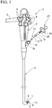
- FIG 1 an endoscope and a suture instrument used in this embodiment are shown.
- An endoscope 1 flexible endoscope
- the endoscope operation unit 2 is connected to a control device via a universal cable 3 and equipped with various switches 4 and angle knobs 5.
- an endoscope insertion part 6 that is flexible and long is extendedly formed.
- an endoscope observation device 7 which obtains an image of the internal body, a lighting unit 8, and a distal end opening of a channel 9 are provided.
- the observation device 7 an imaging device having a CCD (Charge Coupled Device), an optical fiber, and the like can be used.
- the lighting unit 8 has an optical fiber that conducts light from a light source.
- the channel 9 opens at a lateral part 2a of the endoscope operation unit 2 through the endoscope insertion part 6.
- a cap 10 is provided at an opening of the lateral part 2a.
- an insertion hole is formed, and a treatment tool such as a suture instrument 11 or an observation device is inserted into the channel 9 through this insertion hole.
- an inner sheath 13 which is a flexible base is passed through the inside of a flexible outer sheath 12 so as to be able to freely move forward or backward.
- a hollow needle 14 having a sharp tip is fixed.
- a slit 15 extends in the lengthwise direction of the needle 14 from the distal end thereof.
- a suture tool 16 is contained inside of the outer sheath 12 and the needle 14.
- Each of the lengths of the outer sheath 12 and the inner sheath 13 is longer than that of the channel 9 of the endoscope 1.
- an operation unit 17 is provided at the proximal end on a hand side of the inner sheath 13 (hereinbelow, the base end).
- the operation unit 17 has a handle 19 which can freely slide with respect to a main body 18 of the operation unit. To the handle 19, a base end of a pusher 20 is fixed. The pusher 20 extends through the inside of the inner sheath 13 to the inside of the needle 14. A distal end portion 21 of the pusher 20 is pressed against an anchor 27 of the suture tool 16.
- the suture tool 16 has a suture thread 25.
- the suture thread 25 is folded approximately in two and a knot 31 is formed in the vicinity of its turn-around point. Moreover, the suture thread 25 is bundled at both end portions thereof and passed through a stopper 26 that is substantially triangular.
- an anchor 27 is fixed to each end portion of the suture thread 25, an anchor 27 is fixed.
- the anchor 27 has a cylindrical shape and the suture thread 25 is fixed at the approximately center portion in a longitudinal direction of the anchor 27.
- the stopper 26 includes a long, thin plate member in which a hole 28 is formed at the center portion in a longitudinal direction thereof, through which the suture thread 25 is passed.
- Both end portions 29 in a longitudinal direction of the stopper 26 are diagonally folded back to hold the suture thread 25 therebetween. Both end portions 29 in a longitudinal direction of the stopper 26 are cut to form triangular sections 30. Both end portions 29 of the stopper 26 are diagonally folded back so that the sections 30 intersect with each other to hold the suture thread 25 therebetween. As a result, the suture thread 25 is prevented from passing through a space formed between end portions 29.
- both end portions 29 of the stopper 26 are slightly opened. Accordingly, the stopper 26 allows the suture thread 25 to move in this direction.
- the suture tool 16 sequentially houses two anchors 27 in an inner hole of the needle 14 that functions as an anchor holding instrument.
- the suture thread 25 is drawn out from the slit 15 of the needle 14.
- the stopper 26 is held at a more distal end portion than the needle 14 in the outer sheath 12.
- the number of the anchors 27 and the shape of the stopper 26 are not limited to the embodiment shown in the figures.
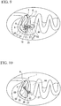
- FIGS. 5 to 12 are pattern diagrams illustrating procedure and show the stomach as an example of a hollow organ.
- the endoscope insertion part 6 is inserted from the mouth (including a natural opening of a living body, such as the anus, nose, or ear) of a patient 41 prepared with a mouthpiece 40.
- a perforation 42 can be checked by the observation device 7 from the inside of the stomach 43 (the inside of the hollow organ).
- an observation device (second observation device) 50 is passed through the channel 9 of the endoscope 1.
- the observation device 50 is, for example, a catheter having a camera at the tip thereof.
- the observation device 50 may be a long and narrow fiberscope.
- the distal end of the observation device 50 is inserted into an abdominal cavity 44 from the perforation 42, and the distal end of the observation device 50 is bent back by a wire or the like which is not shown in the figures.
- an area around the perforation 42 to be punctured with the needle 14 (referred also to as a puncture position or a position through which the needle 14 passes) is observed from an abdominal cavity 44 side (which is also the side at which the anchor 27 is placed), that is, from the outer side of the stomach 43 (referred also as a body cavity side of the hollow organ or the abdominal cavity side) to check that other tissues such as the small intestine, the liver, or the like do not exist at the position through which the needle 14 is passed in order to prevent these tissues from being punctured or sutured together.
- the suture instrument 11 is projected to puncture the tissue around the perforation 42 with the needle 14 while observing the stomach 43 from the abdominal cavity 44 side by the observation device 50.
- the needle 14 is projected from the outer sheath 12 as shown in FIG. 3 .
- the stopper 26 which is contained at the more distal end portion than the needle 14 is extruded from the outer sheath 12 into the stomach 43.
- the needle 14 punctures the tissue.
- the pusher 20 moves forward, and the first anchor 27 is pushed out from the tip of the needle 14 into the abdominal cavity 44, as shown in FIG 8 .
- the pusher 20 is stopped, and the needle 14 is drawn out from the tissue.
- the first anchor 27 remains on the abdominal cavity 44 side.
- the suture thread 25 penetrates through the tissue. Note that the stopper 26 exists inside of the stomach 43.
- the needle 14 is thrust again at an approximately symmetrical position with respect to the position at which the needle 14 is previously thrust centered about the perforation 42.
- the pusher 20 is moved forward.
- the second anchor 27 is pushed out into the abdominal cavity 44.
- the suture thread 25 penetrates through the tissue, and the second anchor 27 is released to the side of the abdominal cavity 44 so as to sandwich the perforation 42 therebetween.
- the suture thread 25 is pulled so that the anchor 27 and the stopper 26 tighten up the tissue, and thereby the perforation 42 is sutured.
- a forceps 60 shown in FIG. 11 is used.
- the forceps 60 is passed through the channel 9 in the place of the observation device 50.
- the forceps 60 has an outer sheath 61 having an external diameter larger than the anchor 27 and an inner sheath 62 passed through the outer sheath 61 so as to freely move forward or backward.
- a supporting member 63 is provided, and a pair of grip segments 64 is supported on the supporting member 63 so as to freely open or close.
- the outer sheath 61 is moved forward to press the tip of the outer sheath 61 against the stopper 26. As shown in FIG. 12 , when the outer sheath 61 moves further forward, the stopper 26 is pushed into the wall of the stomach 43. Since the stopper 26 is constructed to be able to move in this direction, the stopper 26 moves toward the wall. Since the position of the pair of the grip segments 64 does not change, the stopper 26 moves relatively forward with respect to the suture thread 25. As a result, the distance between the stopper 26 and the anchor 27 decreases.
- tissue When a hollow organ such as the small intestine large intestine or another organ such as the spleen or the liver (hereinafter, merely referred to as tissue) exists around the perforation 42 (the position through which the needle 14 is passed), the other tissue is excluded from the stomach 43 by inserting an excluding device.
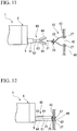
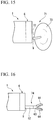
- the excluding device used in this case is exemplified in FIGS. 13 to 16 .
- An excluding device shown in FIG 13 is a rod 70 of which a tip portion can be bent. When the rod 70 is bent, the other hollow organ is excluded to form a space through which the needle 14 is passed.
- An excluding device shown in FIGS. 14 and 15 is a balloon catheter 71.
- an excluding device shown in FIG 16 is a forceps 74.
- an optical fiber or an observation device having a CCD may be provided. When the observation device is provided, it becomes possible to exclude other tissues while observing the state of the abdominal cavity 44.
- the perforation 42 is observed from the inside of the stomach 43 by the observation device 7 of the endoscope 1 at first, and the perforation 42 is then observed from the abdominal cavity 44 side by the observation device 50.
- the suture instrument 11 is made to penetrate through the tissue around the perforation 42 to mount the suture tool 16, and the perforation 42 is sutured by using this suture tool 16. Accordingly, it is possible to suture the perforation 42 after respectively checking from the inside (the side from which the needle 14 is thrust) and the outside (the side through which the needle 14 penetrates or at which the anchor 27 is placed) of the stomach 43 that another tissue does not exist around the perforation 42.
- FIGS. 17 to 22 Modified examples of this embodiment are shown in FIGS. 17 to 22 .
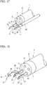
- FIG. 17 two external sheaths 80 are provided at the periphery of the endoscope insertion part 6.
- a suture instrument 11 is passed through each external sheath 80 so as to freely move forward or backward.
- the anchors 27 are individually contained in the respective needles 14. It is possible to thrust two needles 14 into the tissue at the same time or in an arbitrary order.
- one external sheath 80 may be used, and two anchors 27 may be contained in one needle 14.
- FIG. 18 shows an example in which the suture instruments 11 are individually passed through two channels 9 of the endoscope insertion part 6.
- the endoscope insertion part 6 is inserted into an overtube 81.
- a lumen 82 is provided, and the suture instrument 11 is passed through the lumen 82.
- two lumens 82 may be provided, and the suture instruments 11 may be individually passed through each of the lumens 82.
- a channel 84 may be provided at the periphery of the endoscope insertion part 6, and the observation device 50 may be passed through this channel 84. Moreover, the observation device 50 may be directly provided at the periphery of the endoscope insertion part 6 without using the channel 84.
- an external channel 85 may be provided parallel to the endoscope insertion part 6, and the suture instrument 11 may be passed through the channel 85.
- the tip portion of this channel 85 can be bent.
- the suture instrument 11 may be passed through the lumen 82 formed inside of the overtube 81.
- the area around the perforation 42 is observed from the abdominal cavity 44 side by using the observation device 7 of the endoscope insertion part 6.
- FIG. 5 the endoscope insertion part 6 is inserted into the vicinity of the perforation 42 to observe the perforation 42 from the inside of the stomach 43.
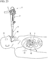
- FIG. 23 the endoscope insertion part 6 is moved from the perforation 42 into the abdominal cavity 44, and an area around the perforation 42 is then observed from the abdominal cavity 44 side by the observation device (first observation device) 7 of the endoscope insertion part 6.
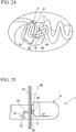
- the needle 14 of the suture instrument 11 is projected from the endoscope insertion part 6 as shown in FIG 24 , and the needle 14 is thrust from the abdominal cavity 44 side into the stomach 43.
- the inside of the stomach 43 may not be checked when thrusting the needle 14.
- the inside of the stomach 43 may be punctured while observing the inside of the stomach 43 (the side at which the anchor 27 is placed) by using another observation device. In this case, it is possible to puncture at the puncture position while observing from both the inner side of the stomach 43 and the abdominal cavity 44 side.
- the first anchor 27 is extruded into the stomach 43 from the tip of the needle 14.
- the suture instrument 11 is contained inside of the channel 9. After that, the endoscope 1 is drawn back to the inside of the stomach 43.
- the forceps 60 is passed through the channel 9 of the endoscope 1 drawn back to the inside of the stomach 43.
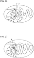
- the forceps 60 grasps the knot 31 of the suture thread 25 existing in the abdominal cavity 44 side, and draws the suture thread 25 and the stopper 26 into the inside of the stomach 43 through the perforation 42.
- FIG. 29 when the stopper 26 is pressed against the tissue by the outer sheath 61, the suture tool 16 tightens up the tissue, and thereby the perforation 42 is sutured.
- the endoscope 1 after observation of the inner side of the stomach 43 by using the endoscope 1, the endoscope 1 is moved to the outer side of the stomach 43 to check by the observation device 7 from the abdominal cavity 44 side that other tissues do not exist in the area around the perforation 42. After that, the needle 14 is thrust into the tissue from the outer side to mount the suture tool 16 and suture the perforation 42 while maintaining the endoscope 1 passing through the perforation 42. Accordingly, other tissues can be easily prevented from being sutured together when suturing by using the endoscope 1.
- FIG. 5 the endoscope insertion part 6 is inserted in the vicinity of the perforation 42 to observe the perforation 42 from the inside of the stomach 43.
- FIG. 23 the endoscope insertion part 6 is moved from the perforation 42 into the abdominal cavity 44, and an area around the perforation 42 is then observed from the abdominal cavity 44 side by the observation device (first observation device) 7 of the endoscope insertion part 6.
- the endoscope insertion part 6 is drawn back to the inside of the stomach 43.
- the suture instrument 11 which is passed through the channel 9 is projected. As shown in FIG 30 , the tip portion of the suture instrument 11 is moved from the perforation 42 to the abdominal cavity 44. The tip portion of the suture instrument 11 is then bent to face the outer side of the stomach 43 and an area around the perforation 42 in the abdominal cavity 44.
- the suture instrument 11 projects the needle 14 from the outer sheath 12, and the needle 14 penetrates the tissue around the perforation 42 from the abdominal cavity 44 side into the inside of the stomach 43. It is preferable that the stopper 26 be made to enter the inside of the stomach 43 when the needle 14 is projected from the outer sheath 12.
- the first anchor 27 is pushed out and ejected to the inner side of the stomach 43.
- FIG. 33 after placement of two anchors 27 inside the stomach 43 so as to sandwich the perforation 42 therebetween, the suture instrument 11 is drawn back to the inside of the stomach 43, and contained in the channel 9.
- the forceps 60 is then passed through the channel 9, and the tissue is tightened up by the suture tool 16 using the forceps 60 to suture the perforation 42.
- the suturing method is the same as in the second embodiment.
- the endoscope 1 is drawn back to the inside of the stomach 43, and the tissue is punctured with the needle 14 from the outer side of the stomach 43. Accordingly, other tissues can be easily prevented from being sutured together when suturing by using the endoscope 1.
- a channel 91 may be provided at the periphery of the endoscope insertion part 6, and the suture instrument 11 may be passed through this channel 91. Moreover, the suture instrument 11 may be directly provided parallel to the periphery of the endoscope insertion part 6. The tip portion of the suture instrument 11 is constructed so as to be able to be independently bent.
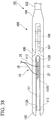
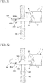
- a treatment portion 103 that is a tip position changing mechanism is fixed at the tip which is the remote end of a sheath 102 that is a flexible base in a suture instrument 101.
- the treatment portion 103 has a support member 104 that is fixed to the sheath 102, and a first forceps piece 105 integrally extends from the tip of the support member 104.
- a second forceps piece 106 (opening-closing member) is supported to the support member 104 so as to freely rotate by a pin 107. A portion of the second forceps piece 106 that is more to the base end side than the pin 107 is pulled into the support member 104 and connected to a link mechanism 108.
- the link mechanism 108 is connected to a forceps wire 109 that is passed through the sheath 102 so as to be able to freely move forward or backward.
- the forceps wire 109 is moved forward or backward, the second forceps piece 106 rotates with respect to the support member 104, and so it is possible to open and close the pair of forceps pieces 105, 106.
- the operation unit 17 that performs the opening-closing operation (refer to FIG. 1 ) is fixed to the base end of the sheath 102.
- the first forceps piece 105 may be constituted to perform the opening-closing operation.
- Slits 110, 111 are formed in the pair of forceps pieces 105, 106, respectively, along the lengthwise direction thereof.
- a hollow needle 112 is disposed in the slit 111 of the second forceps piece 106.
- a tip 112A on the distal end side of the needle 112 that functions as an anchor holding instrument is disposed at the distal end portion of the second forceps piece 106, and is supported to rotate freely at the second forceps piece 106 by a pin 113.
- the base end side of the needle 112 is disposed at the base end side of the slit 111 and is a sharp tip 112B.
- the entire needle 112 is housed in the slit 111 of the second forceps piece 106 in the closed state.
- the needle 112 is approximately parallel with the lengthwise direction of the sheath 102, and the sharp tip 112A faces the base end side, that is, the proximal end side, of the sheath 102.
- a slit 112C extends to a predetermined length in the needle 112 from the sharp tip 112B to the tip 112A, and the suture thread 25 is drawn out from this slit 112C.
- a pusher sheath 115 is connected to the side of the tip 112A of the needle 112.
- the pusher sheath 115 passes through the respective slits 110, 111 of the pair of forceps pieces 105, 106 and extends along the sheath 102 to be drawn out to the hand side.
- the pusher 20 that pushes out the anchors 27 of the suture tool 16 is passed in the pusher sheath 115 so as to be able to freely move forward or backward.
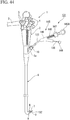
- a position operating device (operation unit 121) that operates the tip position changing mechanism is used by being pulled out from the endoscope 1.
- the operation unit 121 has an operation unit body 122 at which the base end portion of the sheath 102 is fixed.
- a ring 122A for placing a finger is provided on the operation unit body 122, and a slider 123 that is able to freely move forward or backward in the lengthwise direction of the sheath 102 is attached further to the distal end side than the ring 122A.
- the forceps wire 109 is fixed to the slider 123, and when the slider 123 is made to move forward or backward with respect to the operation unit body 122, the pair of forceps pieces 105, 106 can be opened and closed.
- a pusher sheath 115 is passed to be able to freely move forward or backward.
- the pusher sheath 115 is drawn out from a position that is separated from the slider 123 by the operation unit body 122 branching into two lines.
- a pusher sheath knob 124 is provided so as to be easily grasped by an operator at the end portion of the pusher sheath 115 that is drawn out from the operation unit body 122.
- the pusher 20 is further drawn out from the pusher sheath knob 124.
- a pusher knob 125 is provided so as to be easily grasped by an operator at the end portion of the pusher 20.
- the endoscope insertion part 6 When suturing a perforation, as shown in FIG 5 , the endoscope insertion part 6 is inserted until the vicinity of the perforation 42, and performs observation of the perforation 42 from within the stomach 43. Next, as shown in FIG 23 , the endoscope insertion part 6 is fed from the perforation 42 into the abdominal cavity 44, and observation of the perimeter of the perforation 42 is made from the abdominal cavity 44 side with an observation device (first observation device) 7 of the endoscope insertion part 6. After confirmation that other tissue is not in an area around the perforation 42 (the position through with the needle 112 passes, the puncture position, or the position where the anchor 27 is placed), the endoscope insertion part 6 is drawn back into the stomach 43.
- first observation device 7 observation device
- the treatment portion 103 is protruded through the perforation 42 to the outer side of the organ that is the suture object (for example, the stomach 43) with the pair of forceps pieces 105, 106 closed.
- the second forceps piece 106 opens with respect to the first forceps piece 105.
- the second forceps piece 106 that include the needle 112 moves in a direction intersecting with the axial line of the sheath 102.
- the pusher sheath knob 124 the pusher sheath 115 is pushed out.
- the needle 112 that is pushed by the pusher sheath 115 rotates about the pin 113 to come out from the slit 111 of the second forceps piece 106, and the sharp tip 112B of the needle 112 faces the proximal side of the sheath 102, that is, the outer surface of the tissue around the perforation 42, at a position that is offset with respect to the axial line of the sheath 102.
- the needle 112 penetrates the stomach 43 from the outer side to the inner side.
- the pusher knob 125 As shown in FIG 41 , to push in the pusher 20, a first anchor 27 is pushed out from the needle 112.
- the needle 112 is removed from the tissue.
- the suture thread 25 penetrates through the tissue, and the first anchor 27 remains in the stomach 43.
- the suture instrument 101 is rotated about its axial line, and the needle 112 is moved to the opposite side of the location where the suture thread 25 was passed centered about the perforation 42.
- the needle 112 penetrates the stomach 43 from the outer side to the inner side.
- the pusher 20 is pushed further in, and a second anchor 27 is pushed out from the needle 14.
- the pusher sheath knob 124 grasping the pusher sheath knob 124, the pusher sheath 115 is retracted, and the needle 112 is housed in the slit 111 of the second forceps piece 106.
- the pair of forceps pieces 105, 106 is closed.
- the needle 112 is passed from the outer side to the inner side of the tissue, it is possible to reliably pierce the needle 112. Since it is possible to place the suture tool 16 just by the opening-closing operation and the extending and retracting of the pusher sheath 115 and the pusher 20, the operation is simple. Note that the pair of forceps pieces 105, 106 can be used for holding tissue.
- a suture instrument 131 has a lumen 134 in a sheath 132 that is a flexible base.
- An attraction surface 132A is provided so as to close the distal end of the lumen 134.
- An attraction instrument 136 is passed in the lumen 134 so as to move freely forward or backward.
- the distal end portion 136A of the attraction instrument 136 is made from a magnetic material.
- a support portion 137 extends approximately along the lengthwise direction so as to avoid the opening of the lumen 134.
- a hollow needle 139 is supported so at to rotate freely by a pin 138.
- the needle 139 extends in an elongated manner from the end portion of the distal end side that is supported by the pin 138, and the other end portion at the base end side becomes a sharp tip 139A.
- the needle 139 is approximately parallel to the sheath 132, and the sharp tip 139A is aimed at the base end side of the sheath 132, that is, the proximal end side.
- An operation wire 140 that constitutes the tip position changing mechanism is fixed to the sharp tip 139A of the needle 139.
- the operation wire 140 passes through the distal end of the support portion 137 to be drawn out to the hand side.
- the needle 139 rotates about the pin 138, and rises as shown by the virtual lines.
- the operation wire 140 has a predetermined hardness, and so by pushing in the operation wire 140, the needle 139 is housed so as to approximately follow the support portion 137, that is, to become approximately parallel to the lengthwise direction of the sheath 132. Note that by providing a groove in the support portion 137, the operation wire 140 passes along the groove, and so dropping out of the operation wire 140 is prevented.
- Anchors 141 of the suture tool 16 are housed in the needle 139. In the suture tool 16, besides the two anchors 141 being manufactured from permanent magnets, it is the same as the suture tool 16.
- the anchors 141 are housed in the needle 139 so that the same magnetic poles face each other. In FIG 43 , the S-poles face each other.
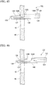
- an operation unit 145 that is a position operating device of the suture instrument 131 has an operation unit body 146 at which the sheath 132 is fixed.
- a ring 146A for placing a finger is provided on the operation unit body 146, and a slider 147 that is able to freely move forward or backward in the lengthwise direction of the sheath 132 is attached.
- the operation wire 140 is attached to the slider 147, and when the slider 147 is made to move forward or backward, the needle 136 can be housed and deployed.
- the operation unit body 146 branches into two lines, and the attraction instrument 136 is drawn out to a position that is separated from the slider 147.
- a knob 148 that can be easily grasped by the operator is formed at the end portion of the attraction instrument 136.
- the procedure when suturing the perforation 42 with this suture tool 131 involves sequentially observing the inner side and outer side of the stomach 43 similarly to the third embodiment.
- the treatment portion 133 is protruded from the perforation 42 to the outer side.
- the needle 139 deploys by inclining in the direction intersecting with the axial line of the sheath 132 centered on the pin 138.
- the sharp tip 139A of the needle 139 is directed toward the tissue, that is, the proximal end side of the sheath 132.
- the needle 139 penetrates the stomach 43 from the outer side to the inner side.
- the attraction instrument 136 By grasping the knob 148 that is pulled out from the operation unit 145 to push in the attraction instrument 136, as shown in FIG 46 , the attraction instrument 136 is moved toward the needle 139 from the inner side of the stomach 43.
- An attraction works between the distal end portion 136A of the attraction instrument 136 and the first anchor 141, whereby the anchor 141 is drawn toward the attraction surface 132A, and as shown in FIG 47 , the first anchor 141 is taken out from the needle 139.
- the first anchor 141 has been suctioned onto the attraction surface 132A, as shown in FIG. 48 , by moving the attraction instrument 136 backward in the lumen 134, it is possible to cause the first anchor 141 to separate from the attraction surface 132A.
- the needle 139 After removing the needle 139 from the tissue by moving the entire suture instrument 131 forward, it is rotated about its axial line, to move the needle 139 to the opposite side centered about the perforation 42. Similarly, by moving the suture instrument 131 backward, the needle 139 penetrates the stomach 43 from the outer side to the inner side. By bringing the attraction instrument 136 closer, the second anchor 141 is pulled out. By moving forward the entire suture tool 131, the needle 139 is removed from the tissue, and after the needle 139 is aligned with the support portion 137, the suture tool 131 is removed from the endoscope 1. Then, the perforation 42 is closed by tightening the suture tool 16 with the forceps 60 similarly to FIG. 28 and FIG 29 .
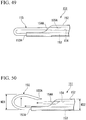
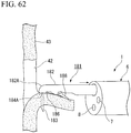
- two lumens 153, 154 are formed approximately parallel in the lengthwise direction in the sheath 152 that is a flexible base.
- the first lumen 153 has an opening 153A at the distal end, and a needle 155 is passed therethrough so as to move freely forward or backward.
- the second lumen 154 has a distal end opening 154A which is formed further to the base end side than the distal end opening 153A deg. of the first lumen 153.
- the needle 155 is hollow and long, and is made from a shape-memory alloy.
- a sharp tip 155A of the needle 155 protrudes from the distal end opening 153A of the first lumen 153, and after being elastically deformed in an approximate U-shape, is inserted from the distal end opening 154A to the second lumen 154 so as to be capable of being freely taken out and put in. That is, the sharp tip 155A is disposed approximately parallel with the sheath 152 and disposed facing the proximal end of the sheath 152.
- the needle 155 is an anchor housing tool in which two anchors 27 (not illustrated in FIG. 49 ) of the suture tool 16 are housed at the sharp end portion 155A.
- the anchors 27 can be pushed out by the pusher 20 that is passed through the needle 155.
- the needle 155 is curved in a loop shape and stores a shape so that the sharp tip portion 155A faces the base end side.
- the curved needle 155 deploys in the direction of intersecting the axial line of the sheath 152.
- An external width WD1 of the needle 155 at this time is greater than an external width WD2 of the sheath 152.
- the curved portion of the needle 155 is a tip position changing mechanism, and the end portion at the hand side of the needle 155 is a position operation device.
- the procedure when suturing the perforation 42 with this suture tool 151 involves sequentially observing the inner side and outer side of the stomach 43 similarly to the third embodiment.
- the suture instrument 151 is protruded to the outer side from the perforation 42 until the formation position of the distal end opening 154A of the second lumen 154.
- the needle 155 is pushed with respect to the sheath 152, the sharp tip 155A of the needle 155 comes out from the second lumen 154.
- the needle 155 deploys due to the self-restoring force, and the sharp tip 155A moves from a position that is approximately parallel to the sheath 152 to a position that is offset from the axial line of the sheath 152 to be directed at tissue around the perforation 42.
- the needle 155 penetrates the stomach 43 from the outer side to the inner side.
- the suture instrument 151 is moved forward to remove the needle 155 from the tissue, and then similarly passed through tissue on the opposite side of the perforation 42.
- a second anchor 27 is pushed out and released by the pusher 20
- the needle 155 is removed from the tissue and then the suture instrument 151 is withdrawn.
- the perforation 42 is closed by tightening the suture tool 16 with the forceps 60 similarly to FIG 28 and FIG 29 .
- the needle 155 that is made to have a shape memory is curved to be housed in the second lumen 154, whereby the suture instrument 151 can be readily passed through the endoscope 1 and the perforation 42.
- the needle 155 When deploying the needle 155, it only needs to be moved forward, so the operation is easy.
- a hollow needle 163 that is an anchor holding instrument is passed through a sheath 162 that is a flexible base.
- the needle 163 has flexibility, and after a curving portion 164 that is a deflection mechanism is provided at a portion protruding from the sheath 162, a sharp tip 163A that is to be passed through tissue is provided.
- the curving portion 164 has a constitution in which a plurality of curving pieces 165 is connected in the lengthwise direction.
- Each curving piece 165 consists of a hollow member, and each base end portion and distal end portion thereof is attached by a pin 167 to another adjacent curving piece 165 so as to rotate freely.
- each curving control member 168 that consists of a shape-memory alloy is extended between each curving piece 165.
- Each curving control member 168 is disposed at the same position in the circumferential direction viewed from the center line of the needle 163, and each is wound in a coil shape in the initial state. That is, in the initial state, the needle 163 is disposed approximately parallel with the axial line of the sheath 162, and the sharp tip 163A faces the remote end direction of the sheath 162.
- the curving control member 168 can be restored to an approximately straight shape by passing electricity, heat generation, or body temperature. For this reason, the position operation device of this suture instrument 161 is the curving control member 168 itself in the case of restoring to the original shape by a device that passes electricity through or generates heat in the curving control member 168, or by body heat.
- the procedure when suturing the perforation 42 with this suture instrument 161 involves sequentially observing the inner side and outer side of the stomach 43 similarly to the third embodiment.
- the needle 163 In the state of contracting the curving control members 168 into a coil shape, that is, in the state of the needle 163 being disposed so as to be approximately parallel to the sheath 162, the needle 163 is passed through the perforation 42.
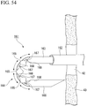
- the curving portion 164 is projected to the outer side from the perforation 42, electrical current is supplied to the curving control members 168 or the curving control members 168 are heated.
- each curving control members 168 is extended by reverting to the original shape, as shown in FIG 54 , the adjacent curving pieces 165 and the needle 163 are pushed in a certain direction.
- the curving portion 164 curves substantially in a U-shape, and the sharp tip 163A of the needle 163 is directed from the remote end direction of the sheath 162 to the proximal end side, that is, the tissue.
- the needle 163 By extending and retracting movement of the needle 163, the needle 163 penetrates the stomach 43 from the outer side to the inner side, and the first anchor 27 is pushed out from the needle 163 by the pusher 20.
- the suture thread 25 is passed through at two locations that sandwich the perforation 42 and the anchors 27 are pushed out and released into the inner side of the stomach 43, the suture instrument 161 is withdrawn from the endoscope 1. Then, the perforation 42 is closed by tightening the suture tool 16 with the forceps 60 similarly to FIG 28 and FIG. 29 .
- the curving control members 168 that consist of a shape-memory metal are not limited to a shape that winds a coil in a coil shape. Also, the curving control members 168 may be a plate-shaped member that curves by being supplied electrical current or the like. It is possible to use the plate-shaped curving control members 168 together with the curving pieces 165 or in place of the curving pieces 165.
- a preferred suture instrument for the suture method in the third embodiment is described.
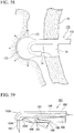
- a needle 14 is passed in a sheath 172 that is a flexible base so as to be able to move backward or forward.
- a balloon 173 that is a deflection mechanism is integrally formed at the distal end portion of the sheath 172.
- the balloon 173 is provided at only a portion of the outer circumferential surface, and does not continue over the entire circumference. Therefore, it is offset from the center line of the needle 14 that passes through the center of the sheath 172.
- a fluid supply device position operation device
- the balloon 173 swells as shown in FIG. 56 and FIG. 57
- the sheath 172 curves by being pressed by the balloon 173. Since the balloon 173 is disposed so that the sheath 172 curves in an approximate U-shape, the sharp tip of the needle 14 is directed from the distal direction of the sheath 172 toward the proximal end side, that is toward the tissue, and so it is possible to pierce through the tissue from the outer side to the inner side.
- an outside organ 175 that is in the area of the tissue that is the suture object is excluded by the swelling of the balloon 173.
- a preferred suture instrument for the suture method in the third embodiment is described.
- a needle 183 is passed in a sheath 182 that is a flexible base so as to be able to move backward or forward.
- Two lumens 184, 185 are formed approximately parallel in the sheath 182. Since a curving portion 182A that functions as a deflection mechanism is formed at the distal end that is a remote end of the sheath 182, a first lumen 184 forms an opening 184A at the side portion by being curved approximately 90 degrees.
- a hollow needle 183 that is an anchor holding instrument is passed through the first lumen 184 so as to freely move forward or backward. It is preferable to manufacture the needle 183 with a super-resilient alloy, so that even when passing through a lumen that is positioned at the curving portion 182A, a permanent deformation is not produced.
- the second lumen 185 is curved by approximately 90 degrees by the curving portion 182A, and at further to the base end side than the first lumen 185, an opening 185A is formed at the same side portion in the circumferential direction.
- An operation wire 186 is passed through the second lumen 185 so as to be able to freely move forward or backward.
- the operation wire 186 is fixed to the distal end portion of an erecting hook 188 that is supported in the sheath 182 so as to freely rotate by a pin 187 further to the base end side than the opening 185A.
- the erecting hook 188 can be housed in a recessed portion 189 that is formed in the sheath 182 so that the distal end portion thereof faces the hand side. Thereby, when the operation wire 186 is pulled, the erecting hook 188 deploys to the outer side as shown by the virtual lines.
- an operation unit 190 that is the position operation device of the suture instrument 181 is constituted to include a base end portion 182B of the sheath 182.
- the needle 183 and the operation wire 186 are separately pulled out from the base end portion 182B.
- An operation unit body 191 is fixed to the needle 183.
- a ring 191 A for placing a finger is provided on the operation unit body 191, and a slider 192 that is able to freely move forward and backward in the lengthwise direction is attached.
- a pusher 20 is fixed to the slider 192.
- a knob 193 that can be easily grasped by the operator is formed at the end portion of the operation wire 182.
- the needle 183 is pierced through the tissue after it has been drawn in with the erecting hook 188, it is possible to place the suture tool 16 with a simple operation. Moreover, by drawing in the tissue with the erecting hook 188, it is possible to observe with the endoscope 1 the position and piercing process when thrusting the needle 183 without curved deformation of the needle 183 by approximately 180 degrees as in other embodiments. Instead of hooking the tissue on the erecting hook 188, the tissue may also be sandwiched between the erecting hook 188 and the sheath 182.
- the curving portion 182A at the distal end of the sheath 182 may be an angle that allows the needle 183 to pierce through the tissue in cooperation with the erecting hook 188, and may be greater than 0 degrees and equal to or less than 90 degrees, compared to the case of curving by approximately 180 degrees, the operation of moving the pusher 20 forward and backward and pushing out of the anchors 27 can be reasonably performed with a light force.
- an inner sheath 13 that functions as an anchor holding instrument that is a flexible base is passed inside of a flexible outer sheath 12 so as to freely move forward and backward.
- a slit 15 that opens at the distal end is provided along the lengthwise direction of the side portion.
- two anchors 27 of the suture tool 16 are housed in line.
- the pusher 20 is made to abut the base end side anchor 27. Note that as the operation unit of this suture instrument 210, it is possible to use the same one as the operation unit 17 shown in FIG. 1 .
- FIG. 65 shows a high-frequency knife that is an example of a treatment instrument.
- the high-frequency knife 211 has a long sheath 212 having flexibility, and an operation unit 213 is provided at the base end of the sheath 212.
- a slider 215 that is able to move forward and backward with respect to the operation unit body 214 and a ring 214A for placing a finger are provided in the operation unit 23.
- the end portion of a long electrode 216 is fixed to the slider 215.
- the electrode 216 is electrically connected to an electrode cable 217 via a terminal 215A that is provided in the slider 215.
- the electrode cable 217 is connected to a high-frequency power supply not illustrated.
- the electrode 216 passes through the sheath 212 so as to be capable of freely moving forward and backward, and extends to the distal end of the sheath 212.
- the electrode 216 is housed in the sheath 212.
- the distal end portion of the electrode 216 protrudes from the sheath 212.
- the high-frequency knife 211 is passed through the channel 9 of the endoscope 1, and a small incision hole 220 is formed from the inner side to the outer side in tissue around the perforation 42.
- the slider 215 is moved forward to cause the electrode 216 to protrude from the sheath 212.
- the distal end of the electrode 216 is pressed against the predetermined position to form the small incision hole 220.
- the small incision hole 220 is formed at two locations sandwiching the perforation 42, the supply of high-frequency current is stopped. After housing the electrode 216 in the sheath 212, the high-frequency knife 211 is removed from the endoscope.
- the suture thread 25 is passed through the small incision hole 220 and then anchors 27 are placed one at a time.
- the suture instrument 201 is passed through the endoscope 1, and the inner sheath 13 is protruded from the outer sheath 12. At this time, the inner sheath 13 abuts the stopper 26 with a wide area, and pushes out the stopper 26 from the outer sheath 12 into the stomach 43.
- the outer sheath 12 of the suture instrument 201 is protruded into the abdominal cavity 44 through the perforation 42.
- the distal end portion of the outer sheath 12 is curved, and the outer sheath 13 is directed from a direction toward the remote end of the suture instrument 201 to a direction toward the proximal end, that is, to the tissue.
- the inner sheath 12 forward it passes through the small incision hole 220 from the outer side to the inner side. Since the inner sheath 13 protrudes from the abdominal cavity 44 into the stomach 43, when the pusher 20 is moved forward as shown in FIG. 69 , the first anchor 27 is pushed out and released in the stomach 43.
- the inner sheath 13 is drawn out from the small incision hole 220.
- the suture thread 25 passes through the small incision hole 220.
- the inner sheath 13 is similarly passed through the small incision hole 220 on the opposite side.
- this suture instrument 201 is of a constitution that does not have a needle, a wide contact surface with the stopper 26 is provided, and so the stopper 26 can easily and reliably be pushed out from the outer sheath 12.
- each suture instrument from the fourth embodiment to the eight embodiment it is possible to use an anchor holding instrument such as shown in the ninth embodiment in place of a needle, with the anchors being released after passing the anchor holding instrument through a small incision hole that is formed with another treatment tool.
- the endoscope 1 may be inserted from the anus into the large intestine which is an example of a hollow organ.
- a perforation formed in the large intestine is sutured.
- the procedure of the above-mentioned embodiment may be carried out after forming the perforation 42 by using the endoscope 1.
- the endoscope 1 is inserted from a natural opening into the inside of the stomach 43, and a predetermined incision portion is checked by the observation device 7 provided at the tip of the endoscope insertion part 6. After that, the predetermined incision portion is incised after passing a high-frequency knife or the like through the channel 9 of the endoscope 1 to form the perforation 42.
- suture tools 16 plurally lined up are preferably sequentially tightened up from one end thereof.
- a suture tool 16a, a suture tool 16b, a suture tool 16c, a suture tool 16d, and a suture tool 16e are tightened up in this order, for example. Since the perforation 42 is sutured from one end thereof, and the size of the perforation 42 can be gradually diminished, suturing can be easily carried out.
- the suture tool 16 at the center of the suture tools 16 lined up may be tightened up first, followed by tightening the suture tools 16 at the center positions between the suture tool 16 tightened up at the center position and the suture tools 16 at the ends thereof.
- the suture tool 16c is tightened up first, the suture tool 16b and the suture tool 16d are then tightened up, and the suture tool 16a and the suture tool 16e are finally tightened up. Since the center position of the opening is always sutured, the degree of slippage of suture positions can be diminished.
- the suture instrument according to this invention may be preferably utilized for medical applications.
Landscapes
- Health & Medical Sciences (AREA)
- Life Sciences & Earth Sciences (AREA)
- Surgery (AREA)
- Heart & Thoracic Surgery (AREA)
- Engineering & Computer Science (AREA)
- Biomedical Technology (AREA)
- Nuclear Medicine, Radiotherapy & Molecular Imaging (AREA)
- Medical Informatics (AREA)
- Molecular Biology (AREA)
- Animal Behavior & Ethology (AREA)
- General Health & Medical Sciences (AREA)
- Public Health (AREA)
- Veterinary Medicine (AREA)
- Cardiology (AREA)
- Surgical Instruments (AREA)
Claims (13)
- Instrument de suture (101, 131, 151) apte à être introduit dans un corps et à éjecter des ancrages allongés (27, 141) auxquels un fil de suture (25) est relié, comprenant :une base (13, 102, 152) qui s'étend d'une extrémité proximale sur un côté main à une extrémité éloignée qui est introduite dans un tissu, la base (13, 102, 152) étant capable d'être introduite dans une perforation et ayant une flexibilité ;un instrument de maintien d'ancrage (112, 139, 155) qui est capable de loger une pluralité d'ancrages (27, 141) à l'intérieur, l'instrument de maintien d'ancrage (112, 139, 155) étant disposé et logé dans l'extrémité éloignée de la base (13, 102, 152) le long d'un axe de la base (13, 102, 152) de telle sorte que l'extrémité distale de l'instrument de maintien d'ancrage (112, 139, 155) est approximativement dirigée dans une direction d'une extrémité proximale de la base (13, 102, 152) ;un mécanisme de changement de position de pointe (103, 140) apte à déplacer l'extrémité distale de l'instrument de maintien d'ancrage (112, 139, 155) dans une direction radiale coupant la ligne axiale de la base (13, 102, 152) d'une position dans laquelle l'instrument de maintien d'ancrage (112, 139, 155) est logé dans la base (13, 102, 152) à une position dans laquelle l'extrémité distale de l'instrument de maintien d'ancrage (112, 139, 155) est espacée d'une extrémité distale de la base (13, 102, 152) et est approximativement dirigée dans la direction de l'extrémité proximale de la base (13, 102, 152) ; etun dispositif d'actionnement de position (17, 121, 145, 190) qui actionne le mécanisme de changement de position de pointe (103, 140) sur le côté main et actionne une position de l'extrémité distale de l'instrument de maintien d'ancrage (112, 139, 155),caractérisé par le fait qu'une extrémité distale de l'instrument de maintien d'ancrage (112, 139, 155) est apte à être introduite dans le tissu et à éjecter les ancrages (27, 141).
- Instrument de suture (101, 131, 151) selon la revendication 1, dans lequel le mécanisme de changement de position de pointe (103, 140) change la position en amenant l'instrument de maintien d'ancrage (112, 139, 155) à se déplacer à une position qui est décalée par rapport à une ligne axiale dans une direction longitudinale de la base (13, 102, 152).
- Instrument de suture (101, 131, 151) selon la revendication 1, dans lequel le mécanisme de changement de position de pointe (103, 140) change la position en inclinant l'instrument de maintien d'ancrage (112, 139, 155) par rapport à une ligne axiale dans une direction longitudinale de la base (13, 102, 152).
- Instrument de suture (101, 131, 151) selon l'une quelconque des revendications 1 à 3, dans lequel l'instrument de maintien d'ancrage (112, 139, 155) est une aiguille (112, 139, 155) qui a à l'extrémité distale une pointe acérée.
- Instrument de suture (101, 131, 151) selon l'une quelconque des revendications 1 à 3, dans lequel l'extrémité distale de l'instrument de maintien d'ancrage (112, 139, 155) consiste en une aiguille creuse (112, 139, 155), et les ancrages (27, 141) sont disposés dans l'aiguille (112, 139, 155).
- Instrument de suture (101, 131, 151) selon l'une quelconque des revendications 1 à 5, comprenant en outre un instrument d'attraction (136) qui attire les ancrages (27, 141) avec une force magnétique, dans lequel :la base a une lumière (134) ;l'instrument d'attraction (136) est disposé le long de la lumière (134) de la base (13, 102, 152) de façon à avancer et se rétracter librement, et les ancrages (27, 141) ;et l'instrument d'attraction (136) sont tous les deux réalisés à partir d'un corps magnétique, et l'un d'eux est un aimant.
- Instrument de suture (161) apte à être introduit dans un corps et à éjecter des ancrages allongés (27, 141) auxquels un fil de suture (25) est relié, comprenant:une base (162) qui s'étend d'une extrémité proximale sur un côté main à une extrémité éloignée apte à être introduite dans un tissu, la base (162) étant capable d'être introduite dans une perforation et ayant une flexibilité ; etun instrument de maintien d'ancrage (163) qui est disposé à l'extrémité éloignée de la base (13, 102, 152, 162) et est capable de loger une pluralité d'ancrages (27, 141) à l'intérieur,une extrémité distale de l'instrument de maintien d'ancrage (163) est apte à être introduite dans le tissu et à éjecter les ancrages (27, 141), l'extrémité distale de l'instrument de maintien d'ancrage (163) étant disposée et logée dans le côté d'extrémité éloignée de la base (162), l'instrument de maintien d'ancrage (163) étant dirigé dans l'extrémité éloignée de la base (162) le long d'un axe de la base (162) ;l'instrument de suture (161) comprenant en outre :un mécanisme de déviation (164) qui est prévu pour dévier une position de l'extrémité distale de l'instrument de maintien d'ancrage (163) et amène l'extrémité distale de l'instrument de maintien d'ancrage (163) à dévier depuis l'extrémité éloignée de la base (162) vers une direction qui fait face à l'extrémité proximale ; etl'instrument de maintien d'ancrage (163) est capable de pénétrer dans un tissu dans un état dans lequel la position de l'extrémité distale de l'instrument de maintien d'ancrage (163) qui fait saillie à partir de la base (162) est déviée dans une direction allant de l'extrémité distale de la base (162) vers une extrémité proximale de la base (162) par le mécanisme de déviation (164) et est capable d'éjecter les ancrages (27, 141) à un côté proximal du tissu,caractérisé par le fait que le mécanisme de déviation (164) comprend une pluralité de pièces d'incurvation (165), une pluralité d'axes (167) reliant les pièces d'incurvation (165) à des pièces d'incurvation adjacentes de façon à tourner librement autour des axes (167), et un élément de commande d'incurvation (168) fait de matériau à mémoire de forme et disposé dans une ligne le long du mécanisme de déviation (164) sur le côté de l'élément de commande d'incurvation (168), le mécanisme de déviation (164) est configuré pour dévier la position de l'extrémité distale de l'instrument de maintien d'ancrage (163) par l'élément de commande d'incurvation (168) qui est ramené à une forme initiale.
- Instrument de suture (161) selon la revendication 7, dans lequel le mécanisme de déviation (164) change la position en inclinant l'instrument de maintien d'ancrage (163) par rapport à une ligne axiale dans la direction longitudinale de la base (162).
- Instrument de suture (161) selon la revendication 7 ou 8, dans lequel l'instrument de maintien d'ancrage (163) est une aiguille qui a à l'extrémité distale une pointe acérée.
- Instrument de suture (161) selon la revendication 7 ou 8, dans lequel l'extrémité distale de l'instrument de maintien d'ancrage (163) consiste en une aiguille creuse, et les ancrages (27, 141) sont disposés dans l'aiguille.
- Instrument de suture (161) selon l'une quelconque des revendications 7 à 10, comprenant en outre un instrument d'attraction (136) qui attire les ancrages (27, 141) avec une force magnétique, dans lequel :la base a une lumière (134), l'instrument d'attraction (136) est disposé le long de la lumière (134) de la base (162) de façon à avancer ou se rétracter librement, et les ancrages (27, 141) et l'instrument d'attraction (136) sont tous les deux réalisés à partir d'un corps magnétique, et l'un d'eux est un aimant.
- Instrument de suture (101, 131, 151) selon la revendication 1, dans lequel l'extrémité distale de l'instrument de maintien d'ancrage (112, 139, 155) est dirigée vers l'extrémité proximale de la base (13, 102, 152) de façon à être parallèle à la base (13, 102, 152).
- Instrument de suture (101, 131, 151) selon la revendication 1, dans lequel l'instrument de maintien d'ancrage (112, 139, 155) a une extrémité distale acérée (112A, 139A, 136A), et
l'instrument de maintien d'ancrage (112, 139, 155) est capable de pénétrer dans un tissu d'un côté distal à un côté proximal du tissu en déplaçant un instrument de suture entier (101, 131, 151) vers l'arrière dans un état dans lequel l'instrument de maintien d'ancrage (112, 139 155) est disposé à une position dans laquelle il est séparé de la base (13, 102, 152) par le mécanisme de changement de position de pointe (103, 140).
Applications Claiming Priority (3)
| Application Number | Priority Date | Filing Date | Title |
|---|---|---|---|
| US11/238,016 US8758375B2 (en) | 2005-09-28 | 2005-09-28 | Method for suturing perforation |
| US11/238,017 US7722631B2 (en) | 2005-09-28 | 2005-09-28 | Method for suturing perforation |
| PCT/JP2006/319335 WO2007037335A1 (fr) | 2005-09-28 | 2006-09-28 | Dispositif de suture |
Publications (3)
| Publication Number | Publication Date |
|---|---|
| EP1938761A1 EP1938761A1 (fr) | 2008-07-02 |
| EP1938761A4 EP1938761A4 (fr) | 2013-04-17 |
| EP1938761B1 true EP1938761B1 (fr) | 2017-03-15 |
Family
ID=39446221
Family Applications (2)
| Application Number | Title | Priority Date | Filing Date |
|---|---|---|---|
| EP06810746.5A Not-in-force EP1938760B1 (fr) | 2005-09-28 | 2006-09-28 | Dispositif de suture |
| EP06810782.0A Not-in-force EP1938761B1 (fr) | 2005-09-28 | 2006-09-28 | Dispositif de suture |
Family Applications Before (1)
| Application Number | Title | Priority Date | Filing Date |
|---|---|---|---|
| EP06810746.5A Not-in-force EP1938760B1 (fr) | 2005-09-28 | 2006-09-28 | Dispositif de suture |
Country Status (4)
| Country | Link |
|---|---|
| US (5) | US8758375B2 (fr) |
| EP (2) | EP1938760B1 (fr) |
| JP (1) | JP4885868B2 (fr) |
| WO (2) | WO2007037335A1 (fr) |
Families Citing this family (339)
| Publication number | Priority date | Publication date | Assignee | Title |
|---|---|---|---|---|
| US7662161B2 (en) | 1999-09-13 | 2010-02-16 | Rex Medical, L.P | Vascular hole closure device |
| US8758400B2 (en) | 2000-01-05 | 2014-06-24 | Integrated Vascular Systems, Inc. | Closure system and methods of use |
| US6391048B1 (en) | 2000-01-05 | 2002-05-21 | Integrated Vascular Systems, Inc. | Integrated vascular device with puncture site closure component and sealant and methods of use |
| US7842068B2 (en) | 2000-12-07 | 2010-11-30 | Integrated Vascular Systems, Inc. | Apparatus and methods for providing tactile feedback while delivering a closure device |
| US6461364B1 (en) | 2000-01-05 | 2002-10-08 | Integrated Vascular Systems, Inc. | Vascular sheath with bioabsorbable puncture site closure apparatus and methods of use |
| US9579091B2 (en) | 2000-01-05 | 2017-02-28 | Integrated Vascular Systems, Inc. | Closure system and methods of use |
| JP2004508092A (ja) | 2000-09-08 | 2004-03-18 | コールマン ジェイムス イー | 外科用ステープラ |
| US6626918B1 (en) | 2000-10-06 | 2003-09-30 | Medical Technology Group | Apparatus and methods for positioning a vascular sheath |
| US7211101B2 (en) | 2000-12-07 | 2007-05-01 | Abbott Vascular Devices | Methods for manufacturing a clip and clip |
| US7905900B2 (en) | 2003-01-30 | 2011-03-15 | Integrated Vascular Systems, Inc. | Clip applier and methods of use |
| US8690910B2 (en) | 2000-12-07 | 2014-04-08 | Integrated Vascular Systems, Inc. | Closure device and methods for making and using them |
| US7806904B2 (en) | 2000-12-07 | 2010-10-05 | Integrated Vascular Systems, Inc. | Closure device |
| US6623510B2 (en) | 2000-12-07 | 2003-09-23 | Integrated Vascular Systems, Inc. | Closure device and methods for making and using them |
| IES20010547A2 (en) | 2001-06-07 | 2002-12-11 | Christy Cummins | Surgical Staple |
| US6749621B2 (en) | 2002-02-21 | 2004-06-15 | Integrated Vascular Systems, Inc. | Sheath apparatus and methods for delivering a closure device |
| US8614768B2 (en) * | 2002-03-18 | 2013-12-24 | Raytheon Company | Miniaturized imaging device including GRIN lens optically coupled to SSID |
| CA2488688A1 (fr) | 2002-06-04 | 2003-12-11 | Christy Cummins | Clip de fermeture pour vaisseau sanguin et dispositif d'apport |
| US8905937B2 (en) | 2009-02-26 | 2014-12-09 | Integrated Vascular Systems, Inc. | Methods and apparatus for locating a surface of a body lumen |
| US8821534B2 (en) | 2010-12-06 | 2014-09-02 | Integrated Vascular Systems, Inc. | Clip applier having improved hemostasis and methods of use |
| US8398656B2 (en) | 2003-01-30 | 2013-03-19 | Integrated Vascular Systems, Inc. | Clip applier and methods of use |
| US7857828B2 (en) | 2003-01-30 | 2010-12-28 | Integrated Vascular Systems, Inc. | Clip applier and methods of use |
| US8202293B2 (en) | 2003-01-30 | 2012-06-19 | Integrated Vascular Systems, Inc. | Clip applier and methods of use |
| US8758398B2 (en) | 2006-09-08 | 2014-06-24 | Integrated Vascular Systems, Inc. | Apparatus and method for delivering a closure element |
| US20050113855A1 (en) * | 2003-08-11 | 2005-05-26 | Kennedy Kenneth C.Ii | Surgical implant |
| IES20040368A2 (en) | 2004-05-25 | 2005-11-30 | James E Coleman | Surgical stapler |
| US7905904B2 (en) * | 2006-02-03 | 2011-03-15 | Biomet Sports Medicine, Llc | Soft tissue repair device and associated methods |
| US9801708B2 (en) | 2004-11-05 | 2017-10-31 | Biomet Sports Medicine, Llc | Method and apparatus for coupling soft tissue to a bone |
| US8118836B2 (en) | 2004-11-05 | 2012-02-21 | Biomet Sports Medicine, Llc | Method and apparatus for coupling soft tissue to a bone |
| US8361113B2 (en) | 2006-02-03 | 2013-01-29 | Biomet Sports Medicine, Llc | Method and apparatus for coupling soft tissue to a bone |
| US8303604B2 (en) | 2004-11-05 | 2012-11-06 | Biomet Sports Medicine, Llc | Soft tissue repair device and method |
| US7909851B2 (en) | 2006-02-03 | 2011-03-22 | Biomet Sports Medicine, Llc | Soft tissue repair device and associated methods |
| US7749250B2 (en) | 2006-02-03 | 2010-07-06 | Biomet Sports Medicine, Llc | Soft tissue repair assembly and associated method |
| US8128658B2 (en) | 2004-11-05 | 2012-03-06 | Biomet Sports Medicine, Llc | Method and apparatus for coupling soft tissue to bone |
| US7601165B2 (en) | 2006-09-29 | 2009-10-13 | Biomet Sports Medicine, Llc | Method and apparatus for forming a self-locking adjustable suture loop |
| US8137382B2 (en) | 2004-11-05 | 2012-03-20 | Biomet Sports Medicine, Llc | Method and apparatus for coupling anatomical features |
| US9017381B2 (en) | 2007-04-10 | 2015-04-28 | Biomet Sports Medicine, Llc | Adjustable knotless loops |
| US8298262B2 (en) | 2006-02-03 | 2012-10-30 | Biomet Sports Medicine, Llc | Method for tissue fixation |
| US8088130B2 (en) | 2006-02-03 | 2012-01-03 | Biomet Sports Medicine, Llc | Method and apparatus for coupling soft tissue to a bone |
| US8834492B2 (en) * | 2005-05-20 | 2014-09-16 | Neotract, Inc. | Continuous indentation lateral lobe apparatus and method |
| US7850683B2 (en) | 2005-05-20 | 2010-12-14 | Myoscience, Inc. | Subdermal cryogenic remodeling of muscles, nerves, connective tissue, and/or adipose tissue (fat) |
| US8603106B2 (en) | 2005-05-20 | 2013-12-10 | Neotract, Inc. | Integrated handle assembly for anchor delivery system |
| US8628542B2 (en) | 2005-05-20 | 2014-01-14 | Neotract, Inc. | Median lobe destruction apparatus and method |
| US9549739B2 (en) | 2005-05-20 | 2017-01-24 | Neotract, Inc. | Devices, systems and methods for treating benign prostatic hyperplasia and other conditions |
| US8668705B2 (en) | 2005-05-20 | 2014-03-11 | Neotract, Inc. | Latching anchor device |
| US7713266B2 (en) | 2005-05-20 | 2010-05-11 | Myoscience, Inc. | Subdermal cryogenic remodeling of muscles, nerves, connective tissue, and/or adipose tissue (fat) |
| US10925587B2 (en) | 2005-05-20 | 2021-02-23 | Neotract, Inc. | Anchor delivery system |
| US10195014B2 (en) | 2005-05-20 | 2019-02-05 | Neotract, Inc. | Devices, systems and methods for treating benign prostatic hyperplasia and other conditions |
| US7645286B2 (en) | 2005-05-20 | 2010-01-12 | Neotract, Inc. | Devices, systems and methods for retracting, lifting, compressing, supporting or repositioning tissues or anatomical structures |
| US7758594B2 (en) | 2005-05-20 | 2010-07-20 | Neotract, Inc. | Devices, systems and methods for treating benign prostatic hyperplasia and other conditions |
| US8926633B2 (en) | 2005-06-24 | 2015-01-06 | Abbott Laboratories | Apparatus and method for delivering a closure element |
| US8313497B2 (en) | 2005-07-01 | 2012-11-20 | Abbott Laboratories | Clip applier and methods of use |
| US7588583B2 (en) | 2005-09-14 | 2009-09-15 | Rhaphis Medical, Inc. | Suturing device, system and method |
| US20070112362A1 (en) * | 2005-11-14 | 2007-05-17 | Olympus Medical Systems Corp. | Perforation suturing method |
| US9408599B2 (en) | 2006-02-03 | 2016-08-09 | Biomet Sports Medicine, Llc | Method and apparatus for coupling soft tissue to a bone |
| US8506597B2 (en) | 2011-10-25 | 2013-08-13 | Biomet Sports Medicine, Llc | Method and apparatus for interosseous membrane reconstruction |
| US8652171B2 (en) | 2006-02-03 | 2014-02-18 | Biomet Sports Medicine, Llc | Method and apparatus for soft tissue fixation |
| US9078644B2 (en) | 2006-09-29 | 2015-07-14 | Biomet Sports Medicine, Llc | Fracture fixation device |
| US11259792B2 (en) | 2006-02-03 | 2022-03-01 | Biomet Sports Medicine, Llc | Method and apparatus for coupling anatomical features |
| US8968364B2 (en) | 2006-02-03 | 2015-03-03 | Biomet Sports Medicine, Llc | Method and apparatus for fixation of an ACL graft |
| US11311287B2 (en) | 2006-02-03 | 2022-04-26 | Biomet Sports Medicine, Llc | Method for tissue fixation |
| US9538998B2 (en) | 2006-02-03 | 2017-01-10 | Biomet Sports Medicine, Llc | Method and apparatus for fracture fixation |
| US9271713B2 (en) | 2006-02-03 | 2016-03-01 | Biomet Sports Medicine, Llc | Method and apparatus for tensioning a suture |
| US8771352B2 (en) | 2011-05-17 | 2014-07-08 | Biomet Sports Medicine, Llc | Method and apparatus for tibial fixation of an ACL graft |
| US9149267B2 (en) | 2006-02-03 | 2015-10-06 | Biomet Sports Medicine, Llc | Method and apparatus for coupling soft tissue to a bone |
| US8801783B2 (en) | 2006-09-29 | 2014-08-12 | Biomet Sports Medicine, Llc | Prosthetic ligament system for knee joint |
| US8562645B2 (en) | 2006-09-29 | 2013-10-22 | Biomet Sports Medicine, Llc | Method and apparatus for forming a self-locking adjustable loop |
| US8652172B2 (en) | 2006-02-03 | 2014-02-18 | Biomet Sports Medicine, Llc | Flexible anchors for tissue fixation |
| US8562647B2 (en) | 2006-09-29 | 2013-10-22 | Biomet Sports Medicine, Llc | Method and apparatus for securing soft tissue to bone |
| US9468433B2 (en) | 2006-02-03 | 2016-10-18 | Biomet Sports Medicine, Llc | Method and apparatus for forming a self-locking adjustable loop |
| US10517587B2 (en) | 2006-02-03 | 2019-12-31 | Biomet Sports Medicine, Llc | Method and apparatus for forming a self-locking adjustable loop |
| US8597327B2 (en) | 2006-02-03 | 2013-12-03 | Biomet Manufacturing, Llc | Method and apparatus for sternal closure |
| US8808310B2 (en) | 2006-04-20 | 2014-08-19 | Integrated Vascular Systems, Inc. | Resettable clip applier and reset tools |
| ATE546095T1 (de) * | 2006-04-28 | 2012-03-15 | Covidien Ag | Organopexy-werkzeugsatz |
| AU2007268046B2 (en) * | 2006-05-22 | 2012-08-16 | Covidien Lp | Method and apparatus for meniscal repair |
| US8876842B2 (en) * | 2006-05-22 | 2014-11-04 | Covidien Lp | Meniscal repair device |
| CN104688327B (zh) * | 2006-06-13 | 2017-06-09 | 直观外科手术操作公司 | 微创手术系统 |
| US8556930B2 (en) | 2006-06-28 | 2013-10-15 | Abbott Laboratories | Vessel closure device |
| US8500818B2 (en) | 2006-09-29 | 2013-08-06 | Biomet Manufacturing, Llc | Knee prosthesis assembly with ligament link |
| US8672969B2 (en) | 2006-09-29 | 2014-03-18 | Biomet Sports Medicine, Llc | Fracture fixation device |
| US9918826B2 (en) | 2006-09-29 | 2018-03-20 | Biomet Sports Medicine, Llc | Scaffold for spring ligament repair |
| US11259794B2 (en) | 2006-09-29 | 2022-03-01 | Biomet Sports Medicine, Llc | Method for implanting soft tissue |
| US20080103441A1 (en) * | 2006-10-26 | 2008-05-01 | Cook Incorporated | Inside out t-fastener system |
| ATE514382T1 (de) * | 2006-11-30 | 2011-07-15 | Wilson Cook Medical Inc | Gewebeanker zum nahtverschluss von perforationen |
| US9254162B2 (en) | 2006-12-21 | 2016-02-09 | Myoscience, Inc. | Dermal and transdermal cryogenic microprobe systems |
| US12502169B2 (en) | 2007-01-16 | 2025-12-23 | Biomet Sports Medicine, Llc | Soft tissue repair device and associated methods |
| US7655004B2 (en) | 2007-02-15 | 2010-02-02 | Ethicon Endo-Surgery, Inc. | Electroporation ablation apparatus, system, and method |
| US8409185B2 (en) | 2007-02-16 | 2013-04-02 | Myoscience, Inc. | Replaceable and/or easily removable needle systems for dermal and transdermal cryogenic remodeling |
| US7780702B2 (en) * | 2007-02-27 | 2010-08-24 | Olympus Medical Systems Corp. | Suture tool |
| US8128657B2 (en) * | 2007-02-27 | 2012-03-06 | Olympus Medical Systems Corp. | Suture instrument |
| US8308766B2 (en) * | 2007-02-27 | 2012-11-13 | Olympus Medical Systems Corp. | Endoscopic treatment instrument |
| US20080228203A1 (en) * | 2007-03-15 | 2008-09-18 | Minos Medical | System and method for translumenal closure in natural orifice surgery |
| CN101677817B (zh) | 2007-03-15 | 2011-09-28 | 雷菲斯医药公司 | 用于不同针的可替换尖端缝合装置和系统 |
| US8075572B2 (en) | 2007-04-26 | 2011-12-13 | Ethicon Endo-Surgery, Inc. | Surgical suturing apparatus |
| US8100922B2 (en) | 2007-04-27 | 2012-01-24 | Ethicon Endo-Surgery, Inc. | Curved needle suturing tool |
| WO2008147871A1 (fr) * | 2007-05-25 | 2008-12-04 | Wilson-Cook Medical, Inc. | Dispositifs médicaux, systèmes et procédés de fermeture de perforations |
| EP2150183B1 (fr) | 2007-05-31 | 2013-03-20 | Cook Medical Technologies LLC | Arrêt de suture |
| US7835074B2 (en) | 2007-06-05 | 2010-11-16 | Sterling Lc | Mini-scope for multi-directional imaging |
| WO2008152617A2 (fr) | 2007-06-15 | 2008-12-18 | Zerusa Limited | Dispositif de fermeture |
| US8226681B2 (en) | 2007-06-25 | 2012-07-24 | Abbott Laboratories | Methods, devices, and apparatus for managing access through tissue |
| US8187176B2 (en) * | 2007-07-18 | 2012-05-29 | Ethicon Endo-Surgery, Inc. | Device for insufflating the interior of a gastric cavity of a patient |
| US20090024148A1 (en) * | 2007-07-18 | 2009-01-22 | Zeiner Mark S | Method for forming plications of the gastric cavity |
| US20090023997A1 (en) * | 2007-07-18 | 2009-01-22 | Stokes Michael J | device for insufflating the interior of a gastric cavity of a patient |
| EP2178446B1 (fr) * | 2007-08-17 | 2013-05-22 | Cook Medical Technologies LLC | Dispositif pour ouvrir et fermer une paroi corporelle |
| US8262655B2 (en) | 2007-11-21 | 2012-09-11 | Ethicon Endo-Surgery, Inc. | Bipolar forceps |
| US8568410B2 (en) | 2007-08-31 | 2013-10-29 | Ethicon Endo-Surgery, Inc. | Electrical ablation surgical instruments |
| US8579897B2 (en) | 2007-11-21 | 2013-11-12 | Ethicon Endo-Surgery, Inc. | Bipolar forceps |
| AU2008304583B2 (en) | 2007-09-25 | 2012-03-29 | Cook Medical Technologies Llc | Medical devices, systems, and methods for using tissue anchors |
| US7998150B2 (en) | 2007-09-28 | 2011-08-16 | Olympus Medical Systems Corp. | Suturing device |
| US8480657B2 (en) | 2007-10-31 | 2013-07-09 | Ethicon Endo-Surgery, Inc. | Detachable distal overtube section and methods for forming a sealable opening in the wall of an organ |
| US20090112059A1 (en) | 2007-10-31 | 2009-04-30 | Nobis Rudolph H | Apparatus and methods for closing a gastrotomy |
| WO2009065061A1 (fr) | 2007-11-14 | 2009-05-22 | Myoscience, Inc. | Gestion de la douleur à l'aide du remodelage cryogénique |
| US20090157101A1 (en) | 2007-12-17 | 2009-06-18 | Abbott Laboratories | Tissue closure system and methods of use |
| US8893947B2 (en) | 2007-12-17 | 2014-11-25 | Abbott Laboratories | Clip applier and methods of use |
| US7841502B2 (en) | 2007-12-18 | 2010-11-30 | Abbott Laboratories | Modular clip applier |
| WO2009082596A1 (fr) * | 2007-12-18 | 2009-07-02 | Wilson-Cook Medical, Inc. | Dispositif et procédé de placement de sutures dans des tissus |
| WO2009089101A2 (fr) * | 2008-01-03 | 2009-07-16 | Wilson-Cook Medical, Inc. | Systèmes médicaux, dispositifs et procédés de suture de perforations par voie endoscopique |
| US20090182192A1 (en) | 2008-01-14 | 2009-07-16 | Olympus Medical Systems Corp. | Treating tool for endoscope |
| US8070772B2 (en) | 2008-02-15 | 2011-12-06 | Rex Medical, L.P. | Vascular hole closure device |
| US20110029013A1 (en) | 2008-02-15 | 2011-02-03 | Mcguckin James F | Vascular Hole Closure Device |
| US8920463B2 (en) * | 2008-02-15 | 2014-12-30 | Rex Medical, L.P. | Vascular hole closure device |
| US9226738B2 (en) | 2008-02-15 | 2016-01-05 | Rex Medical, L.P. | Vascular hole closure delivery device |
| US8491629B2 (en) * | 2008-02-15 | 2013-07-23 | Rex Medical | Vascular hole closure delivery device |
| US8920462B2 (en) * | 2008-02-15 | 2014-12-30 | Rex Medical, L.P. | Vascular hole closure device |
| EP2098172B1 (fr) | 2008-03-04 | 2017-02-22 | Arthrex, Inc. | Système pour la réparation du ménisque à l'aide d'une construction de sangle d'implant de suture |
| US8262680B2 (en) | 2008-03-10 | 2012-09-11 | Ethicon Endo-Surgery, Inc. | Anastomotic device |
| US20090259232A1 (en) * | 2008-04-11 | 2009-10-15 | Junji Shiono | Suture device |
| US20090287048A1 (en) * | 2008-05-16 | 2009-11-19 | Sterling Lc | Method and apparatus for imaging within a living body |
| US9282965B2 (en) * | 2008-05-16 | 2016-03-15 | Abbott Laboratories | Apparatus and methods for engaging tissue |
| US8652150B2 (en) | 2008-05-30 | 2014-02-18 | Ethicon Endo-Surgery, Inc. | Multifunction surgical device |
| US8317806B2 (en) | 2008-05-30 | 2012-11-27 | Ethicon Endo-Surgery, Inc. | Endoscopic suturing tension controlling and indication devices |
| US8070759B2 (en) | 2008-05-30 | 2011-12-06 | Ethicon Endo-Surgery, Inc. | Surgical fastening device |
| US8679003B2 (en) | 2008-05-30 | 2014-03-25 | Ethicon Endo-Surgery, Inc. | Surgical device and endoscope including same |
| US8771260B2 (en) | 2008-05-30 | 2014-07-08 | Ethicon Endo-Surgery, Inc. | Actuating and articulating surgical device |
| US8114072B2 (en) | 2008-05-30 | 2012-02-14 | Ethicon Endo-Surgery, Inc. | Electrical ablation device |
| US8906035B2 (en) | 2008-06-04 | 2014-12-09 | Ethicon Endo-Surgery, Inc. | Endoscopic drop off bag |
| US8403926B2 (en) | 2008-06-05 | 2013-03-26 | Ethicon Endo-Surgery, Inc. | Manually articulating devices |
| US12108939B2 (en) | 2008-06-17 | 2024-10-08 | Boston Scientific Scimed, Inc. | Endoscopic tissue grasping systems and methods |
| US9486126B2 (en) * | 2008-06-17 | 2016-11-08 | Apollo Endosurgery, Inc. | Endoscopic helix tissue grasping device |
| JP5596027B2 (ja) * | 2008-06-18 | 2014-09-24 | レイセオン カンパニー | カテーテル |
| US8152835B2 (en) * | 2008-06-25 | 2012-04-10 | Tyco Healthcare Group Lp | Methods for the placement of sutures in tissue |
| US8361112B2 (en) | 2008-06-27 | 2013-01-29 | Ethicon Endo-Surgery, Inc. | Surgical suture arrangement |
| US8262563B2 (en) | 2008-07-14 | 2012-09-11 | Ethicon Endo-Surgery, Inc. | Endoscopic translumenal articulatable steerable overtube |
| US8888792B2 (en) | 2008-07-14 | 2014-11-18 | Ethicon Endo-Surgery, Inc. | Tissue apposition clip application devices and methods |
| WO2010014792A2 (fr) | 2008-07-30 | 2010-02-04 | Sterling Lc | Procédé et dispositif permettant une variation par incréments de la longueur d’ondes pour analyser un tissu |
| US8911454B2 (en) | 2008-07-31 | 2014-12-16 | Olympus Medical Systems Corp. | Suturing device |
| US8231640B2 (en) | 2008-07-31 | 2012-07-31 | Olympus Medical Systems Corp. | Suture instrument |
| US8863748B2 (en) * | 2008-07-31 | 2014-10-21 | Olympus Medical Systems Corp. | Endoscopic surgical operation method |
| US8211125B2 (en) | 2008-08-15 | 2012-07-03 | Ethicon Endo-Surgery, Inc. | Sterile appliance delivery device for endoscopic procedures |
| WO2010022060A1 (fr) | 2008-08-19 | 2010-02-25 | Wilson-Cook Medical Inc. | Appareil de retrait de nœuds lymphatiques ou d'ancrage de tissus durant une procédure transluminale |
| US12245759B2 (en) | 2008-08-22 | 2025-03-11 | Biomet Sports Medicine, Llc | Method and apparatus for coupling soft tissue to bone |
| US12419632B2 (en) | 2008-08-22 | 2025-09-23 | Biomet Sports Medicine, Llc | Method and apparatus for coupling anatomical features |
| US8529563B2 (en) | 2008-08-25 | 2013-09-10 | Ethicon Endo-Surgery, Inc. | Electrical ablation devices |
| US8241204B2 (en) | 2008-08-29 | 2012-08-14 | Ethicon Endo-Surgery, Inc. | Articulating end cap |
| US8480689B2 (en) | 2008-09-02 | 2013-07-09 | Ethicon Endo-Surgery, Inc. | Suturing device |
| US8409200B2 (en) | 2008-09-03 | 2013-04-02 | Ethicon Endo-Surgery, Inc. | Surgical grasping device |
| US8114119B2 (en) | 2008-09-09 | 2012-02-14 | Ethicon Endo-Surgery, Inc. | Surgical grasping device |
| US8192461B2 (en) | 2008-09-11 | 2012-06-05 | Cook Medical Technologies Llc | Methods for facilitating closure of a bodily opening using one or more tacking devices |
| EP2344045A1 (fr) * | 2008-09-16 | 2011-07-20 | Ventralfix, Inc. | Procédé et appareil d'administration, de déploiement en tension et de fixation mini-invasifs de dispositifs prothétiques en matériau secondaire dans un tissu corporel d'un patient, et notamment réparation de hernie à l'intérieur du site de la hernie chez le patient |
| US8480686B2 (en) | 2008-09-25 | 2013-07-09 | Ethicon Endo-Surgery, Inc. | Methods and devices for delivering and applying suture anchors |
| US9089320B2 (en) | 2008-09-25 | 2015-07-28 | Ethicon Endo-Surgery, Inc. | Methods and devices for delivering and applying multiple suture anchors |
| US8337394B2 (en) | 2008-10-01 | 2012-12-25 | Ethicon Endo-Surgery, Inc. | Overtube with expandable tip |
| WO2010042402A1 (fr) * | 2008-10-06 | 2010-04-15 | Wilson-Cook Medical, Inc. | Coiffe d’extrémité destinée à déployer de manière sûre des broches de fixation de tissus |
| US8262675B2 (en) | 2008-10-29 | 2012-09-11 | Ethicon Endo-Surgery, Inc. | Methods and devices for applying multiple suture anchors |
| US9241696B2 (en) | 2008-10-30 | 2016-01-26 | Abbott Vascular Inc. | Closure device |
| WO2010053916A2 (fr) * | 2008-11-04 | 2010-05-14 | Sterling Lc | Procédé et dispositif d'imagerie à décalage de longueur d'onde |
| US20100113873A1 (en) | 2008-11-06 | 2010-05-06 | Takayuki Suzuki | Suturing device and suturing system |
| US8157834B2 (en) | 2008-11-25 | 2012-04-17 | Ethicon Endo-Surgery, Inc. | Rotational coupling device for surgical instrument with flexible actuators |
| WO2010062851A1 (fr) | 2008-11-26 | 2010-06-03 | Smith & Nephew, Inc. | Dispositif de réparation de tissu |
| AU2009322353B2 (en) | 2008-12-05 | 2013-04-18 | Cook Medical Technologies Llc | Tissue anchors for purse-string closure of perforations |
| US8500760B2 (en) | 2008-12-09 | 2013-08-06 | Cook Medical Technologies Llc | Retractable tacking device |
| US8172772B2 (en) | 2008-12-11 | 2012-05-08 | Ethicon Endo-Surgery, Inc. | Specimen retrieval device |
| EP2389122B1 (fr) | 2008-12-19 | 2015-03-04 | Cook Medical Technologies LLC | Dispositifs de pince |
| US8323312B2 (en) | 2008-12-22 | 2012-12-04 | Abbott Laboratories | Closure device |
| US8858594B2 (en) | 2008-12-22 | 2014-10-14 | Abbott Laboratories | Curved closure device |
| WO2010075438A1 (fr) | 2008-12-22 | 2010-07-01 | Myoscience, Inc. | Système de cryochirurgie intégré avec fluide frigorigène et source d'énergie électrique |
| US9414820B2 (en) | 2009-01-09 | 2016-08-16 | Abbott Vascular Inc. | Closure devices, systems, and methods |
| US9486191B2 (en) | 2009-01-09 | 2016-11-08 | Abbott Vascular, Inc. | Closure devices |
| US20100179589A1 (en) | 2009-01-09 | 2010-07-15 | Abbott Vascular Inc. | Rapidly eroding anchor |
| US9089311B2 (en) | 2009-01-09 | 2015-07-28 | Abbott Vascular Inc. | Vessel closure devices and methods |
| US9173644B2 (en) | 2009-01-09 | 2015-11-03 | Abbott Vascular Inc. | Closure devices, systems, and methods |
| US8828031B2 (en) | 2009-01-12 | 2014-09-09 | Ethicon Endo-Surgery, Inc. | Apparatus for forming an anastomosis |
| US8361066B2 (en) | 2009-01-12 | 2013-01-29 | Ethicon Endo-Surgery, Inc. | Electrical ablation devices |
| US20100185234A1 (en) | 2009-01-16 | 2010-07-22 | Abbott Vascular Inc. | Closure devices, systems, and methods |
| WO2010083110A1 (fr) | 2009-01-16 | 2010-07-22 | Rhaphis Medical, Inc. | Verrou de suture chirurgicale |
| US9226772B2 (en) | 2009-01-30 | 2016-01-05 | Ethicon Endo-Surgery, Inc. | Surgical device |
| US8252057B2 (en) | 2009-01-30 | 2012-08-28 | Ethicon Endo-Surgery, Inc. | Surgical access device |
| US8037591B2 (en) | 2009-02-02 | 2011-10-18 | Ethicon Endo-Surgery, Inc. | Surgical scissors |
| US8382776B2 (en) | 2009-04-03 | 2013-02-26 | Cook Medical Technologies Llc | Medical devices, systems and methods for rapid deployment and fixation of tissue anchors |
| US8647368B2 (en) | 2009-04-03 | 2014-02-11 | Cook Medical Technologies Llc | Tissue anchors and medical devices for rapid deployment of tissue anchors |
| US8109943B2 (en) * | 2009-04-10 | 2012-02-07 | Gordian Surgical, LLC | Systems and methods for suture anchor deployment |
| EP2424460B1 (fr) * | 2009-04-30 | 2017-05-24 | Cook Medical Technologies LLC | Système pour le déploiement de repères d'alignement |
| US8343227B2 (en) | 2009-05-28 | 2013-01-01 | Biomet Manufacturing Corp. | Knee prosthesis assembly with ligament link |
| WO2010138579A1 (fr) | 2009-05-28 | 2010-12-02 | Wilson-Cook Medical Inc. | Dispositif d'agrafage et procédés de déploiement |
| US12096928B2 (en) | 2009-05-29 | 2024-09-24 | Biomet Sports Medicine, Llc | Method and apparatus for coupling soft tissue to a bone |
| US12551209B2 (en) | 2009-06-22 | 2026-02-17 | Biomet Sports Medicine, Llc | Method and apparatus for coupling soft tissue to a bone |
| EP2452631B1 (fr) * | 2009-07-10 | 2018-03-07 | Educational Foundation Jichi Medical University | Système chirurgical pour fermeture de stomie via un conduit biologique |
| EP2453811B1 (fr) | 2009-07-15 | 2021-09-01 | GT Metabolic Solutions, Inc. | Dispositifs de pontage gastrique sans incision |
| US8828053B2 (en) | 2009-07-24 | 2014-09-09 | Depuy Mitek, Llc | Methods and devices for repairing and anchoring damaged tissue |
| US8814903B2 (en) | 2009-07-24 | 2014-08-26 | Depuy Mitek, Llc | Methods and devices for repairing meniscal tissue |
| US20110054492A1 (en) | 2009-08-26 | 2011-03-03 | Abbott Laboratories | Medical device for repairing a fistula |
| WO2011037977A1 (fr) * | 2009-09-22 | 2011-03-31 | Synthes Usa, Llc | Système de réparation de tissu mou fondé sur une suture d'ancre à multiples points de suture |
| US12616462B2 (en) | 2009-09-30 | 2026-05-05 | Biomet Sports Medicine, Llc | Soft tissue repair device and method |
| WO2011041730A2 (fr) | 2009-10-01 | 2011-04-07 | Jacobsen Stephen C | Appareil de diffusion de la lumière |
| WO2011041728A2 (fr) | 2009-10-01 | 2011-04-07 | Jacobsen Stephen C | Dispositif d'imagerie acheminé par aiguille |
| WO2011041720A2 (fr) | 2009-10-01 | 2011-04-07 | Jacobsen Stephen C | Procédé et appareil de manoeuvre d'un micro-cathéter |
| US20110098704A1 (en) | 2009-10-28 | 2011-04-28 | Ethicon Endo-Surgery, Inc. | Electrical ablation devices |
| US8828028B2 (en) | 2009-11-03 | 2014-09-09 | Raytheon Company | Suture device and method for closing a planar opening |
| US8608652B2 (en) | 2009-11-05 | 2013-12-17 | Ethicon Endo-Surgery, Inc. | Vaginal entry surgical devices, kit, system, and method |
| US8496574B2 (en) | 2009-12-17 | 2013-07-30 | Ethicon Endo-Surgery, Inc. | Selectively positionable camera for surgical guide tube assembly |
| US9072542B2 (en) * | 2009-12-18 | 2015-07-07 | Cook Medical Technologies Llc | System and method for fiducial deployment |
| US9028483B2 (en) | 2009-12-18 | 2015-05-12 | Ethicon Endo-Surgery, Inc. | Surgical instrument comprising an electrode |
| US8506564B2 (en) | 2009-12-18 | 2013-08-13 | Ethicon Endo-Surgery, Inc. | Surgical instrument comprising an electrode |
| EP2512359B8 (fr) * | 2009-12-18 | 2015-09-02 | Cook Medical Technologies LLC | Système de déploiement de repères |
| US11357486B2 (en) | 2009-12-30 | 2022-06-14 | Vivasure Medical Limited | Closure system and uses thereof |
| US10058314B2 (en) | 2010-01-20 | 2018-08-28 | Micro Interventional Devices, Inc. | Tissue closure device and method |
| US9980708B2 (en) | 2010-01-20 | 2018-05-29 | Micro Interventional Devices, Inc. | Tissue closure device and method |
| US10959840B2 (en) | 2010-01-20 | 2021-03-30 | Micro Interventional Devices, Inc. | Systems and methods for affixing a prosthesis to tissue |
| EP2525723B1 (fr) * | 2010-01-20 | 2017-09-20 | Micro Interventional Devices, Inc. | Implant de réparation de tissu et dispositif de délivrance |
| US10743854B2 (en) | 2010-01-20 | 2020-08-18 | Micro Interventional Devices, Inc. | Tissue closure device and method |
| US9005198B2 (en) | 2010-01-29 | 2015-04-14 | Ethicon Endo-Surgery, Inc. | Surgical instrument comprising an electrode |
| US8303624B2 (en) | 2010-03-15 | 2012-11-06 | Abbott Cardiovascular Systems, Inc. | Bioabsorbable plug |
| US8764632B2 (en) | 2010-04-08 | 2014-07-01 | Eric James Kezirian | Endoscopic device and system |
| US9855031B2 (en) * | 2010-04-13 | 2018-01-02 | Neosurgical Limited | Suture delivery system |
| GB2486497B (en) * | 2010-12-17 | 2013-06-19 | Neosurgical Ltd | Laparoscopic trocar system |
| US9743919B2 (en) | 2010-04-27 | 2017-08-29 | DePuy Synthes Products, Inc. | Stitch lock for attaching two or more structures |
| US9451938B2 (en) | 2010-04-27 | 2016-09-27 | DePuy Synthes Products, Inc. | Insertion instrument for anchor assembly |
| US9597064B2 (en) | 2010-04-27 | 2017-03-21 | DePuy Synthes Products, Inc. | Methods for approximating a tissue defect using an anchor assembly |
| AU2011245417B2 (en) | 2010-04-27 | 2015-04-09 | Synthes Gmbh | Anchor assembly including expandable anchor |
| US20110306992A1 (en) | 2010-06-09 | 2011-12-15 | C.R. Bard, Inc. | Instruments for delivering transfascial sutures, transfascial suture assemblies, and methods of transfascial suturing |
| CN102958458B (zh) * | 2010-06-29 | 2015-05-13 | 斯恩蒂斯有限公司 | 用于锚固组件的插入仪器 |
| US20120143225A1 (en) * | 2010-07-06 | 2012-06-07 | Pavilion Medical Innovations | Endoscopic fascial closure devices and methods for using same |
| US8758399B2 (en) | 2010-08-02 | 2014-06-24 | Abbott Cardiovascular Systems, Inc. | Expandable bioabsorbable plug apparatus and method |
| US8603116B2 (en) | 2010-08-04 | 2013-12-10 | Abbott Cardiovascular Systems, Inc. | Closure device with long tines |
| JP5615112B2 (ja) * | 2010-09-21 | 2014-10-29 | 日本コヴィディエン株式会社 | 臓器固定具及び臓器固定具の導入具 |
| ES2399786B1 (es) | 2010-10-07 | 2014-04-02 | Fundacion Para La Investigación Biomédica Del Hospital Universitario La Paz | Dispositivo quirurgico de sutura discontinua |
| WO2012090069A2 (fr) * | 2010-12-30 | 2012-07-05 | Vivasure Medical Limited | Systèmes et procédés de fermeture chirurgicale |
| EP2663240B1 (fr) * | 2011-01-14 | 2017-03-22 | Synthes GmbH | Instrument d'introduction pour ensemble d'ancrage |
| US10092291B2 (en) | 2011-01-25 | 2018-10-09 | Ethicon Endo-Surgery, Inc. | Surgical instrument with selectively rigidizable features |
| US8795334B2 (en) | 2011-01-28 | 2014-08-05 | Smith & Nephew, Inc. | Tissue repair |
| US9233241B2 (en) | 2011-02-28 | 2016-01-12 | Ethicon Endo-Surgery, Inc. | Electrical ablation devices and methods |
| US9314620B2 (en) | 2011-02-28 | 2016-04-19 | Ethicon Endo-Surgery, Inc. | Electrical ablation devices and methods |
| US9254169B2 (en) | 2011-02-28 | 2016-02-09 | Ethicon Endo-Surgery, Inc. | Electrical ablation devices and methods |
| WO2012125785A1 (fr) | 2011-03-17 | 2012-09-20 | Ethicon Endo-Surgery, Inc. | Dispositif chirurgical portatif de manipulation d'un ensemble à aimants interne dans le corps d'un patient |
| US9149276B2 (en) | 2011-03-21 | 2015-10-06 | Abbott Cardiovascular Systems, Inc. | Clip and deployment apparatus for tissue closure |
| US12329373B2 (en) | 2011-05-02 | 2025-06-17 | Biomet Sports Medicine, Llc | Method and apparatus for soft tissue fixation |
| WO2012170692A1 (fr) | 2011-06-08 | 2012-12-13 | Suturenetics, Inc. | Dispositif de sutures à mâchoires décalées, système, et procédés |
| US8838208B2 (en) | 2011-06-28 | 2014-09-16 | Cook Medical Technologies Llc | Fiducial deployment needle system |
| US9357991B2 (en) | 2011-11-03 | 2016-06-07 | Biomet Sports Medicine, Llc | Method and apparatus for stitching tendons |
| US12582395B2 (en) | 2011-11-03 | 2026-03-24 | Biomet Sports Medicine, Llc | Method and apparatus for forming a self-locking adjustable loop |
| US9357992B2 (en) | 2011-11-10 | 2016-06-07 | Biomet Sports Medicine, Llc | Method for coupling soft tissue to a bone |
| US9381013B2 (en) | 2011-11-10 | 2016-07-05 | Biomet Sports Medicine, Llc | Method for coupling soft tissue to a bone |
| US9370350B2 (en) | 2011-11-10 | 2016-06-21 | Biomet Sports Medicine, Llc | Apparatus for coupling soft tissue to a bone |
| US9332976B2 (en) | 2011-11-30 | 2016-05-10 | Abbott Cardiovascular Systems, Inc. | Tissue closure device |
| US9055940B2 (en) | 2011-12-23 | 2015-06-16 | Pavilion Medical Innovations, Llc | Endoscopic fascial closure systems and methods for using same |
| CA2860893A1 (fr) | 2012-01-13 | 2013-07-18 | Myoscience, Inc. | Protection de la peau pour le remodelage sous-cutane cryogenique dans le cadre de soins cosmetiques et autres traitements |
| WO2013106860A1 (fr) | 2012-01-13 | 2013-07-18 | Myoscience, Inc. | Système de filtration de sonde cryogénique |
| WO2013106859A1 (fr) | 2012-01-13 | 2013-07-18 | Myoscience, Inc. | Aiguille cryogénique avec régulation de la zone de congélation |
| US9017318B2 (en) | 2012-01-20 | 2015-04-28 | Myoscience, Inc. | Cryogenic probe system and method |
| US9332886B2 (en) * | 2012-01-30 | 2016-05-10 | Cook Medical Technologies Llc | Fiducial placement system and splayed stylet |
| US8986199B2 (en) | 2012-02-17 | 2015-03-24 | Ethicon Endo-Surgery, Inc. | Apparatus and methods for cleaning the lens of an endoscope |
| US9572558B2 (en) | 2012-02-29 | 2017-02-21 | Vivasure Medical Limited | Devices and methods for delivering implants for percutaneous perforation closure |
| US9084597B2 (en) | 2012-03-09 | 2015-07-21 | Smith & Nephew, Inc. | Suture-based knotless repair |
| US10292801B2 (en) | 2012-03-29 | 2019-05-21 | Neotract, Inc. | System for delivering anchors for treating incontinence |
| US9427255B2 (en) | 2012-05-14 | 2016-08-30 | Ethicon Endo-Surgery, Inc. | Apparatus for introducing a steerable camera assembly into a patient |
| US10130353B2 (en) | 2012-06-29 | 2018-11-20 | Neotract, Inc. | Flexible system for delivering an anchor |
| US9078662B2 (en) | 2012-07-03 | 2015-07-14 | Ethicon Endo-Surgery, Inc. | Endoscopic cap electrode and method for using the same |
| US9545290B2 (en) | 2012-07-30 | 2017-01-17 | Ethicon Endo-Surgery, Inc. | Needle probe guide |
| US9572623B2 (en) | 2012-08-02 | 2017-02-21 | Ethicon Endo-Surgery, Inc. | Reusable electrode and disposable sheath |
| US10314649B2 (en) | 2012-08-02 | 2019-06-11 | Ethicon Endo-Surgery, Inc. | Flexible expandable electrode and method of intraluminal delivery of pulsed power |
| US9277957B2 (en) | 2012-08-15 | 2016-03-08 | Ethicon Endo-Surgery, Inc. | Electrosurgical devices and methods |
| JP5926461B2 (ja) * | 2012-09-21 | 2016-05-25 | ボストン サイエンティフィック ニューロモデュレイション コーポレイション | 組織固定具送出装置 |
| US8986327B2 (en) | 2012-10-18 | 2015-03-24 | Smith & Nephew, Inc. | Flexible anchor delivery system |
| US9364209B2 (en) | 2012-12-21 | 2016-06-14 | Abbott Cardiovascular Systems, Inc. | Articulating suturing device |
| JP5988885B2 (ja) * | 2013-01-30 | 2016-09-07 | オリンパス株式会社 | 治療用処置装置 |
| JP6115178B2 (ja) * | 2013-02-22 | 2017-04-19 | 住友ベークライト株式会社 | 連発式の臓器固定具 |
| KR101793801B1 (ko) * | 2013-02-22 | 2017-11-03 | 스미또모 베이크라이트 가부시키가이샤 | 연발식 장기 고정구 |
| EP2967642B1 (fr) | 2013-02-26 | 2017-02-01 | Cook Medical Technologies LLC | Poignée à cliquet coulissant et système pour le déploiement de repères |
| US10098527B2 (en) | 2013-02-27 | 2018-10-16 | Ethidcon Endo-Surgery, Inc. | System for performing a minimally invasive surgical procedure |
| US9757119B2 (en) | 2013-03-08 | 2017-09-12 | Biomet Sports Medicine, Llc | Visual aid for identifying suture limbs arthroscopically |
| US9918827B2 (en) | 2013-03-14 | 2018-03-20 | Biomet Sports Medicine, Llc | Scaffold for spring ligament repair |
| US9850013B2 (en) | 2013-03-15 | 2017-12-26 | Vivasure Medical Limited | Loading devices and methods for percutaneous perforation closure systems |
| US9610112B2 (en) | 2013-03-15 | 2017-04-04 | Myoscience, Inc. | Cryogenic enhancement of joint function, alleviation of joint stiffness and/or alleviation of pain associated with osteoarthritis |
| US10016229B2 (en) | 2013-03-15 | 2018-07-10 | Myoscience, Inc. | Methods and systems for treatment of occipital neuralgia |
| US9295512B2 (en) | 2013-03-15 | 2016-03-29 | Myoscience, Inc. | Methods and devices for pain management |
| EP2967706B1 (fr) | 2013-03-15 | 2021-09-08 | Pacira CryoTech, Inc. | Dispositifs cryogéniques émoussées de dissection |
| US9579098B2 (en) | 2013-03-15 | 2017-02-28 | King Saud University | Bendable suture needle with free varying angle and holder therefor |
| US10245021B2 (en) | 2013-10-08 | 2019-04-02 | Applied Medical Technology, Inc | Magnetic U-stitch device |
| WO2015069792A1 (fr) | 2013-11-05 | 2015-05-14 | Myoscience, Inc. | Système de traitement cryochirurgical sécurisé |
| EP3081168B1 (fr) * | 2013-12-12 | 2020-02-26 | Olympus Corporation | Aiguille de ponction pour endoscope ultrasonore |
| US10136886B2 (en) | 2013-12-20 | 2018-11-27 | Biomet Sports Medicine, Llc | Knotless soft tissue devices and techniques |
| US20150250470A1 (en) * | 2014-03-05 | 2015-09-10 | Coaxis Medical, Inc. | Suture anchoring system and delivery method |
| US9615822B2 (en) | 2014-05-30 | 2017-04-11 | Biomet Sports Medicine, Llc | Insertion tools and method for soft anchor |
| US9700291B2 (en) | 2014-06-03 | 2017-07-11 | Biomet Sports Medicine, Llc | Capsule retractor |
| CN106456213B (zh) * | 2014-06-09 | 2019-04-12 | 库克医药技术有限责任公司 | 用于基准物部署的螺钉驱动式手柄及系统 |
| US10363407B2 (en) | 2014-06-16 | 2019-07-30 | Cook Medical Technologies Llc | Plunger-driven collet handle and system for fiducial deployment |
| US10039543B2 (en) | 2014-08-22 | 2018-08-07 | Biomet Sports Medicine, Llc | Non-sliding soft anchor |
| WO2016054387A1 (fr) * | 2014-10-01 | 2016-04-07 | Boston Scientific Scimed, Inc. | Étiquettes en t à boucle et crochet et/ou magnétiques |
| WO2016089667A1 (fr) | 2014-12-03 | 2016-06-09 | Cook Medical Technologies Llc | Ensemble poignée de stylet à aiguille repère ultrasonore endoscopique |
| WO2016096930A1 (fr) | 2014-12-15 | 2016-06-23 | Vivasure Medical Limited | Élément pouvant être scellé implantable avec une couche à mailles |
| US10433826B2 (en) | 2014-12-15 | 2019-10-08 | Vivasure Medical Limited | Closure apparatus with flexible sealable member and flexible support member |
| US9955980B2 (en) | 2015-02-24 | 2018-05-01 | Biomet Sports Medicine, Llc | Anatomic soft tissue repair |
| US9974534B2 (en) | 2015-03-31 | 2018-05-22 | Biomet Sports Medicine, Llc | Suture anchor with soft anchor of electrospun fibers |
| WO2017022326A1 (fr) | 2015-08-04 | 2017-02-09 | オリンパス株式会社 | Dispositif de suture |
| CN108289681A (zh) | 2015-10-29 | 2018-07-17 | 阿克松根股份公司 | 具有预置滑轮系统的植入装置 |
| CN108697414B (zh) | 2015-12-15 | 2022-02-01 | 维瓦舒尔医疗设备有限公司 | 利用带狭槽鞋状物实现有利压力分布的动脉切开术封闭设备 |
| US10568617B2 (en) | 2016-04-20 | 2020-02-25 | Medos International Sarl | Meniscal repair devices, systems, and methods |
| EP4349396A3 (fr) | 2016-05-13 | 2024-05-01 | Pacira CryoTech, Inc. | Systèmes de localisation et de traitement par thérapie contre le froid |
| JP2019508204A (ja) * | 2016-05-16 | 2019-03-28 | ボストン サイエンティフィック サイムド,インコーポレイテッドBoston Scientific Scimed,Inc. | 内視鏡縫合および縫合不全引き締め修復装置 |
| US10448938B2 (en) | 2016-06-16 | 2019-10-22 | Phillips Medical, LLC | Methods and systems for sealing a puncture of a vessel |
| EP3537990A4 (fr) * | 2016-11-11 | 2020-08-05 | Tack Surgical, LLC | Articles de suture de fixation et de fermeture de tissu et dispositifs de placement de suture |
| AU2017357804B2 (en) | 2016-11-13 | 2023-06-01 | Anchora Medical Ltd. | Minimally-invasive tissue suturing device |
| US10463362B2 (en) | 2017-04-18 | 2019-11-05 | Durastat Llc | Devices and methods for suture placement |
| US10716551B2 (en) | 2017-05-12 | 2020-07-21 | Phillips Medical, LLC | Systems and methods for sealing a puncture of a vessel |
| US10624620B2 (en) | 2017-05-12 | 2020-04-21 | Phillips Medical, LLC | Systems and methods for sealing a puncture of a vessel |
| US11134998B2 (en) | 2017-11-15 | 2021-10-05 | Pacira Cryotech, Inc. | Integrated cold therapy and electrical stimulation systems for locating and treating nerves and associated methods |
| US20200383679A1 (en) * | 2017-11-27 | 2020-12-10 | T.A.G. Medical Devices - Agriculture Cooperative Ltd. | Multiple anchor delivery system and method |
| WO2019126718A1 (fr) | 2017-12-23 | 2019-06-27 | Neotract, Inc. | Appareil et procédé de mise en prise de tissu extensible |
| WO2019168593A1 (fr) * | 2018-03-01 | 2019-09-06 | Phillips Medical, LLC | Système et procédé d'obturation d'une ponction d'un vaisseau |
| WO2019176131A1 (fr) * | 2018-03-16 | 2019-09-19 | オリンパス株式会社 | Endoscope et système d'endoscope |
| WO2020096827A1 (fr) | 2018-11-07 | 2020-05-14 | Neotract, Inc. | Système d'administration d'un marqueur de repère |
| US11864751B2 (en) | 2018-12-05 | 2024-01-09 | Boston Scientific Scimed, Inc. | Endoscopic tissue approximation system and methods |
| US11504105B2 (en) | 2019-01-25 | 2022-11-22 | Rex Medical L.P. | Vascular hole closure device |
| CN119606453A (zh) * | 2019-05-16 | 2025-03-14 | 波士顿科学国际有限公司 | 组织牵引带和组织牵引的方法 |
| EP3965663A1 (fr) * | 2019-09-06 | 2022-03-16 | Boston Scientific Scimed Inc. | Dispositif de suture |
| US11793508B2 (en) | 2019-09-28 | 2023-10-24 | Tas Medical, Inc. | Systems, devices and methods for tissue fixation and approximating tissue defects |
| US11998205B2 (en) * | 2020-01-13 | 2024-06-04 | Brian Lim | Gastrointestinal tissue approximation clip (GI TAC) system |
| US12064114B2 (en) * | 2020-01-13 | 2024-08-20 | Brian Lim | Gastrointestinal tissue approximation clip (GI TAC) system |
| US12594068B2 (en) | 2020-01-26 | 2026-04-07 | Tas Medical Inc. | Medical systems, devices and methods adapted for tissue fixation and approximating tissue defects |
| US12167844B2 (en) | 2020-03-02 | 2024-12-17 | Boston Scientific Scimed, Inc. | Endoscopic tissue approximation system and methods |
| US12035904B2 (en) | 2020-03-03 | 2024-07-16 | Boston Scientific Scimed, Inc. | Endoscopic tissue approximation system and methods |
| US12178424B2 (en) | 2021-02-04 | 2024-12-31 | Aurora Medical Technologies Corp | Suturing breakaway anchor strip |
| US11819206B2 (en) * | 2021-03-01 | 2023-11-21 | Olympus Medical Systems Corp. | Method for closing wound |
| US11723655B2 (en) * | 2021-05-17 | 2023-08-15 | Applied Medical Technology, Inc. | Magnet-assisted suture graspers |
| KR20240156616A (ko) * | 2022-03-03 | 2024-10-30 | 카디오멕 에이에스 | 심장 복구를 위한 연질 조직 앵커 시스템 |
| USD1081998S1 (en) | 2022-03-17 | 2025-07-01 | Gt Metabolic Solutions, Inc. | Anastomosis formation device |
| JP7790243B2 (ja) * | 2022-03-31 | 2025-12-23 | 日本ゼオン株式会社 | 内視鏡用処置具 |
| US20260102154A1 (en) * | 2022-11-18 | 2026-04-16 | Applied Medical Technology, Inc. | Magnet-assisted suture grasper comprising a suture retrieval needle, a grasper magnet, and a spring |
| JP2025538446A (ja) * | 2022-11-18 | 2025-11-28 | アプライド・メディカル・テクノロジー・インコーポレーテッド | 縫合糸回収針と、把持器フェルールと、把持器磁石と、磁石ワイヤとを備える磁石支援式縫合糸把持器 |
| US20250040919A1 (en) * | 2023-08-01 | 2025-02-06 | Boston Scientific Scimed, Inc. | Drainage devices, systems, and methods |
Citations (4)
| Publication number | Priority date | Publication date | Assignee | Title |
|---|---|---|---|---|
| US5624380A (en) * | 1992-03-12 | 1997-04-29 | Olympus Optical Co., Ltd. | Multi-degree of freedom manipulator |
| US20030045778A1 (en) * | 2000-04-03 | 2003-03-06 | Ohline Robert M. | Tendon-driven endoscope and methods of insertion |
| US20040138525A1 (en) * | 2003-01-15 | 2004-07-15 | Usgi Medical Corp. | Endoluminal tool deployment system |
| US20040225305A1 (en) * | 1999-06-25 | 2004-11-11 | Usgi Medical | Apparatus and methods for forming and securing gastrointestinal tissue folds |
Family Cites Families (51)
| Publication number | Priority date | Publication date | Assignee | Title |
|---|---|---|---|---|
| US4235238A (en) * | 1978-05-11 | 1980-11-25 | Olympus Optical Co., Ltd. | Apparatus for suturing coeliac tissues |
| US5366459A (en) * | 1987-05-14 | 1994-11-22 | Inbae Yoon | Surgical clip and clip application procedures |
| US4947827A (en) * | 1988-12-30 | 1990-08-14 | Opielab, Inc. | Flexible endoscope |
| JPH0332847A (ja) | 1989-06-29 | 1991-02-13 | Nec Corp | 噴射ヘッドの製造方法 |
| US5053041A (en) * | 1990-03-12 | 1991-10-01 | Ansari Shapoor S | Vessel holder |
| DE59203043D1 (de) * | 1991-03-06 | 1995-08-31 | Sueddeutsche Feinmechanik | Kanüle zum ablegen eines elements. |
| JP3032847B2 (ja) | 1991-06-28 | 2000-04-17 | 未来工業株式会社 | 配線・配管材布設装置 |
| US5458131A (en) * | 1992-08-25 | 1995-10-17 | Wilk; Peter J. | Method for use in intra-abdominal surgery |
| US5297536A (en) * | 1992-08-25 | 1994-03-29 | Wilk Peter J | Method for use in intra-abdominal surgery |
| US5222508A (en) * | 1992-10-09 | 1993-06-29 | Osvaldo Contarini | Method for suturing punctures of the human body |
| US5336239A (en) * | 1993-01-15 | 1994-08-09 | Gimpelson Richard J | Surgical needle |
| US5391182A (en) * | 1993-08-03 | 1995-02-21 | Origin Medsystems, Inc. | Apparatus and method for closing puncture wounds |
| US5507754A (en) * | 1993-08-20 | 1996-04-16 | United States Surgical Corporation | Apparatus and method for applying and adjusting an anchoring device |
| US5601571A (en) * | 1994-05-17 | 1997-02-11 | Moss; Gerald | Surgical fastener implantation device |
| JP3375730B2 (ja) | 1994-06-07 | 2003-02-10 | マニー株式会社 | 医療用糸通し具 |
| CA2197066A1 (fr) * | 1995-06-07 | 1996-12-19 | Medtronic, Inc. | Systeme pour la fermeture de plaies |
| US5824009A (en) * | 1995-12-06 | 1998-10-20 | Kabushiki Kaisha Matsutani Seisakusho | Guide instrument for a medical needle with thread |
| US5855585A (en) * | 1996-06-11 | 1999-01-05 | X-Site, L.L.C. | Device and method for suturing blood vessels and the like |
| US5810848A (en) | 1996-08-21 | 1998-09-22 | Hayhurst; John O. | Suturing system |
| US5948002A (en) * | 1996-11-15 | 1999-09-07 | Bonutti; Peter M. | Apparatus and method for use in positioning a suture anchor |
| US6066090A (en) * | 1997-06-19 | 2000-05-23 | Yoon; Inbae | Branched endoscope system |
| US6071292A (en) | 1997-06-28 | 2000-06-06 | Transvascular, Inc. | Transluminal methods and devices for closing, forming attachments to, and/or forming anastomotic junctions in, luminal anatomical structures |
| US6066146A (en) | 1998-06-24 | 2000-05-23 | Carroll; Brendan J. | Laparascopic incision closure device |
| US6352503B1 (en) * | 1998-07-17 | 2002-03-05 | Olympus Optical Co., Ltd. | Endoscopic surgery apparatus |
| US6086596A (en) * | 1999-04-21 | 2000-07-11 | Durham; Alfred A. | Magnetically assisted surgical wiring and cabling passer devices |
| US6835200B2 (en) * | 1999-06-22 | 2004-12-28 | Ndo Surgical. Inc. | Method and devices for tissue reconfiguration |
| US6398796B2 (en) * | 1999-07-13 | 2002-06-04 | Scion Cardio-Vascular, Inc. | Suture with toggle and delivery system |
| US6203554B1 (en) * | 1999-11-23 | 2001-03-20 | William Roberts | Apparatus, kit and methods for puncture site closure |
| US7887551B2 (en) * | 1999-12-02 | 2011-02-15 | Smith & Nephew, Inc. | Soft tissue attachment and repair |
| US6450938B1 (en) * | 2000-03-21 | 2002-09-17 | Promex, Llc | Brachytherapy device |
| WO2001074260A1 (fr) * | 2000-03-24 | 2001-10-11 | Johns Hopkins University | Cavite peritoneale, procede et dispositif |
| MXPA02010751A (es) * | 2000-05-10 | 2003-03-10 | Canica Design Inc | Sistema y metodo para mover y estirar tejido plastico. |
| US6572626B1 (en) * | 2000-10-19 | 2003-06-03 | Ethicon Endo-Surgery, Inc. | Surgical instrument having a fastener delivery mechanism |
| US7033373B2 (en) * | 2000-11-03 | 2006-04-25 | Satiety, Inc. | Method and device for use in minimally invasive placement of space-occupying intragastric devices |
| US6500184B1 (en) * | 2001-01-31 | 2002-12-31 | Yung C. Chan | Suturing apparatus and method of suturing |
| US6535764B2 (en) * | 2001-05-01 | 2003-03-18 | Intrapace, Inc. | Gastric treatment and diagnosis device and method |
| US6719765B2 (en) * | 2001-12-03 | 2004-04-13 | Bonutti 2003 Trust-A | Magnetic suturing system and method |
| US7527590B2 (en) * | 2002-03-19 | 2009-05-05 | Olympus Corporation | Anastomosis system |
| US8105342B2 (en) * | 2002-05-08 | 2012-01-31 | Apollo Endosurgery, Inc. | Apparatus for ligating/suturing living tissues and system for resecting/suturing living tissues |
| EP1511430A1 (fr) | 2002-05-17 | 2005-03-09 | NDO Surgical, Inc. | Procede et dispositifs de restructuration de tissu |
| US6840899B2 (en) * | 2002-08-29 | 2005-01-11 | Kinamed, Inc. | Method and instrument for surgical delivery of biocompatible materials |
| US6966916B2 (en) * | 2002-09-26 | 2005-11-22 | Kumar Sarbjeet S | Device and method for surgical repair of abdominal wall hernias |
| US20090149871A9 (en) | 2002-11-01 | 2009-06-11 | Jonathan Kagan | Devices and methods for treating morbid obesity |
| JP4145200B2 (ja) | 2003-06-06 | 2008-09-03 | オリンパス株式会社 | 縫合器 |
| WO2005034763A1 (fr) * | 2003-09-11 | 2005-04-21 | Nmt Medical, Inc. | Dispositifs, systemes et methodes permettant de suturer un tissu |
| US20050251189A1 (en) * | 2004-05-07 | 2005-11-10 | Usgi Medical Inc. | Multi-position tissue manipulation assembly |
| EP1713402B1 (fr) | 2004-02-13 | 2018-07-04 | Ethicon Endo-Surgery, Inc. | Dispositif pour reduction du volume stomacal |
| US8128640B2 (en) * | 2005-02-07 | 2012-03-06 | Ivy Sports Medicine LLC | System and method for all-inside suture fixation for implant attachment and soft tissue repair |
| WO2006086275A2 (fr) * | 2005-02-07 | 2006-08-17 | Regen Biologics, Inc. | Systeme et procede de fixation integralement interne d'un fil de suture pour la fixation d'un implant et la reparation de tissus mous |
| ES2375738T3 (es) | 2005-07-07 | 2012-03-05 | Cordis Corporation | Dispositivo de cierre de una persistencia del agujero oval con un sistema orientable de administración. |
| US7846179B2 (en) * | 2005-09-01 | 2010-12-07 | Ovalis, Inc. | Suture-based systems and methods for treating septal defects |
-
2005
- 2005-09-28 US US11/238,016 patent/US8758375B2/en active Active
- 2005-09-28 US US11/238,017 patent/US7722631B2/en active Active
- 2005-09-28 US US11/238,019 patent/US7875041B2/en not_active Expired - Fee Related
-
2006
- 2006-09-28 WO PCT/JP2006/319335 patent/WO2007037335A1/fr not_active Ceased
- 2006-09-28 JP JP2007537676A patent/JP4885868B2/ja not_active Expired - Fee Related
- 2006-09-28 WO PCT/JP2006/319299 patent/WO2007037326A1/fr not_active Ceased
- 2006-09-28 EP EP06810746.5A patent/EP1938760B1/fr not_active Not-in-force
- 2006-09-28 EP EP06810782.0A patent/EP1938761B1/fr not_active Not-in-force
-
2008
- 2008-03-28 US US12/057,604 patent/US20080243148A1/en not_active Abandoned
- 2008-03-28 US US12/057,971 patent/US20090125039A1/en not_active Abandoned
Patent Citations (4)
| Publication number | Priority date | Publication date | Assignee | Title |
|---|---|---|---|---|
| US5624380A (en) * | 1992-03-12 | 1997-04-29 | Olympus Optical Co., Ltd. | Multi-degree of freedom manipulator |
| US20040225305A1 (en) * | 1999-06-25 | 2004-11-11 | Usgi Medical | Apparatus and methods for forming and securing gastrointestinal tissue folds |
| US20030045778A1 (en) * | 2000-04-03 | 2003-03-06 | Ohline Robert M. | Tendon-driven endoscope and methods of insertion |
| US20040138525A1 (en) * | 2003-01-15 | 2004-07-15 | Usgi Medical Corp. | Endoluminal tool deployment system |
Also Published As
| Publication number | Publication date |
|---|---|
| US20070073320A1 (en) | 2007-03-29 |
| JPWO2007037326A1 (ja) | 2009-04-09 |
| EP1938760A4 (fr) | 2013-07-24 |
| EP1938761A1 (fr) | 2008-07-02 |
| EP1938760B1 (fr) | 2014-11-12 |
| US20070073321A1 (en) | 2007-03-29 |
| US20080243148A1 (en) | 2008-10-02 |
| US7722631B2 (en) | 2010-05-25 |
| EP1938760A1 (fr) | 2008-07-02 |
| WO2007037335A1 (fr) | 2007-04-05 |
| US20070073322A1 (en) | 2007-03-29 |
| US7875041B2 (en) | 2011-01-25 |
| WO2007037326A1 (fr) | 2007-04-05 |
| JP4885868B2 (ja) | 2012-02-29 |
| US20090125039A1 (en) | 2009-05-14 |
| US8758375B2 (en) | 2014-06-24 |
| EP1938761A4 (fr) | 2013-04-17 |
Similar Documents
| Publication | Publication Date | Title |
|---|---|---|
| EP1938761A1 (fr) | Dispositif de suture | |
| EP1769749B1 (fr) | Instrument chirurgical de suture | |
| US8721657B2 (en) | Medical instrument | |
| JP4675241B2 (ja) | 内視鏡システム | |
| US8337395B2 (en) | Anastomosis system | |
| JP4624485B2 (ja) | 縫合器及び縫合システム | |
| US20070219411A1 (en) | Overtube and endoscopic treatment system | |
| US20080255422A1 (en) | Medical device | |
| US8353920B2 (en) | Suture instrument | |
| EP1702569B1 (fr) | Dispositif d'anastomose et procede pour exciser une partie de paroi d'un organe luminal in vivo | |
| US20030139752A1 (en) | System comprising endoscope and endoscopic instruments | |
| CN104955405A (zh) | 缝合装置 | |
| JP2002336262A (ja) | 組織穿刺装置 | |
| JP2007185495A (ja) | オーバーチューブ | |
| JP2007296351A (ja) | 三重に曲がる括約筋切開器 | |
| JP2007296348A (ja) | 二重に曲がる括約筋切開器 | |
| US8728121B2 (en) | Puncture needle and medical procedure using puncture needle that is performed via natural orifice | |
| JP2012024607A (ja) | 縫合器 | |
| CN108882931B (zh) | 缝合装置 | |
| US20070167676A1 (en) | Overtube and medical procedure via natural orifice using the same | |
| US8857441B2 (en) | Biological tissue transfer method and biological tissue treatment method | |
| US20240285273A1 (en) | Devices and methods for closure of openings in tissue | |
| CN121463906A (zh) | 用于相关于组织执行手术的装置、系统和方法 | |
| WO1999065399A1 (fr) | Instrument de suture avec dispositif d'imagerie solidaire et procede d'utilisation correspondant |
Legal Events
| Date | Code | Title | Description |
|---|---|---|---|
| PUAI | Public reference made under article 153(3) epc to a published international application that has entered the european phase |
Free format text: ORIGINAL CODE: 0009012 |
|
| 17P | Request for examination filed |
Effective date: 20080410 |
|
| AK | Designated contracting states |
Kind code of ref document: A1 Designated state(s): DE FR GB IE |
|
| DAX | Request for extension of the european patent (deleted) | ||
| RBV | Designated contracting states (corrected) |
Designated state(s): DE FR GB IE |
|
| A4 | Supplementary search report drawn up and despatched |
Effective date: 20130314 |
|
| RIC1 | Information provided on ipc code assigned before grant |
Ipc: A61B 17/04 20060101AFI20130308BHEP |
|
| 17Q | First examination report despatched |
Effective date: 20131105 |
|
| RAP1 | Party data changed (applicant data changed or rights of an application transferred) |
Owner name: OLYMPUS CORPORATION |
|
| RAP1 | Party data changed (applicant data changed or rights of an application transferred) |
Owner name: OLYMPUS CORPORATION |
|
| REG | Reference to a national code |
Ref country code: DE Ref legal event code: R079 Ref document number: 602006051987 Country of ref document: DE Free format text: PREVIOUS MAIN CLASS: A61B0017040000 Ipc: A61B0017000000 |
|
| RAP1 | Party data changed (applicant data changed or rights of an application transferred) |
Owner name: OLYMPUS CORPORATION |
|
| GRAP | Despatch of communication of intention to grant a patent |
Free format text: ORIGINAL CODE: EPIDOSNIGR1 |
|
| RIC1 | Information provided on ipc code assigned before grant |
Ipc: A61B 17/00 20060101AFI20160928BHEP Ipc: A61B 17/06 20060101ALN20160928BHEP Ipc: A61B 17/02 20060101ALN20160928BHEP Ipc: A61B 17/04 20060101ALI20160928BHEP |
|
| INTG | Intention to grant announced |
Effective date: 20161026 |
|
| RAP1 | Party data changed (applicant data changed or rights of an application transferred) |
Owner name: OLYMPUS CORPORATION |
|
| RIN1 | Information on inventor provided before grant (corrected) |
Inventor name: SATO, MASATOSHI Inventor name: IWASAKA, MASAYUKI Inventor name: MIKKAICHI, TAKAYASU Inventor name: SUZUKI, TAKAYUKI Inventor name: HAYASHI, KENSUKE Inventor name: SHIONO, JUNJI Inventor name: KAJI, KUNIHIDE |
|
| GRAS | Grant fee paid |
Free format text: ORIGINAL CODE: EPIDOSNIGR3 |
|
| GRAA | (expected) grant |
Free format text: ORIGINAL CODE: 0009210 |
|
| AK | Designated contracting states |
Kind code of ref document: B1 Designated state(s): DE FR GB IE |
|
| REG | Reference to a national code |
Ref country code: GB Ref legal event code: FG4D |
|
| REG | Reference to a national code |
Ref country code: DE Ref legal event code: R082 Ref document number: 602006051987 Country of ref document: DE Representative=s name: WUESTHOFF & WUESTHOFF, PATENTANWAELTE PARTG MB, DE |
|
| REG | Reference to a national code |
Ref country code: IE Ref legal event code: FG4D |
|
| REG | Reference to a national code |
Ref country code: DE Ref legal event code: R096 Ref document number: 602006051987 Country of ref document: DE |
|
| REG | Reference to a national code |
Ref country code: DE Ref legal event code: R097 Ref document number: 602006051987 Country of ref document: DE |
|
| PLBE | No opposition filed within time limit |
Free format text: ORIGINAL CODE: 0009261 |
|
| STAA | Information on the status of an ep patent application or granted ep patent |
Free format text: STATUS: NO OPPOSITION FILED WITHIN TIME LIMIT |
|
| 26N | No opposition filed |
Effective date: 20171218 |
|
| GBPC | Gb: european patent ceased through non-payment of renewal fee |
Effective date: 20170928 |
|
| REG | Reference to a national code |
Ref country code: IE Ref legal event code: MM4A |
|
| REG | Reference to a national code |
Ref country code: FR Ref legal event code: ST Effective date: 20180531 |
|
| PG25 | Lapsed in a contracting state [announced via postgrant information from national office to epo] |
Ref country code: IE Free format text: LAPSE BECAUSE OF NON-PAYMENT OF DUE FEES Effective date: 20170928 Ref country code: GB Free format text: LAPSE BECAUSE OF NON-PAYMENT OF DUE FEES Effective date: 20170928 |
|
| PG25 | Lapsed in a contracting state [announced via postgrant information from national office to epo] |
Ref country code: FR Free format text: LAPSE BECAUSE OF NON-PAYMENT OF DUE FEES Effective date: 20171002 |
|
| PGFP | Annual fee paid to national office [announced via postgrant information from national office to epo] |
Ref country code: DE Payment date: 20210920 Year of fee payment: 16 |
|
| REG | Reference to a national code |
Ref country code: DE Ref legal event code: R119 Ref document number: 602006051987 Country of ref document: DE |
|
| PG25 | Lapsed in a contracting state [announced via postgrant information from national office to epo] |
Ref country code: DE Free format text: LAPSE BECAUSE OF NON-PAYMENT OF DUE FEES Effective date: 20230401 |