EP1940156A2 - Fernsehsystem mit installierter Telefonfunktion und darauf gerichtete Fernsteuerungsvorrichtung - Google Patents
Fernsehsystem mit installierter Telefonfunktion und darauf gerichtete Fernsteuerungsvorrichtung Download PDFInfo
- Publication number
- EP1940156A2 EP1940156A2 EP07024834A EP07024834A EP1940156A2 EP 1940156 A2 EP1940156 A2 EP 1940156A2 EP 07024834 A EP07024834 A EP 07024834A EP 07024834 A EP07024834 A EP 07024834A EP 1940156 A2 EP1940156 A2 EP 1940156A2
- Authority
- EP
- European Patent Office
- Prior art keywords
- transmission
- audio signal
- reception unit
- remote controller
- audio
- Prior art date
- Legal status (The legal status is an assumption and is not a legal conclusion. Google has not performed a legal analysis and makes no representation as to the accuracy of the status listed.)
- Ceased
Links
- 230000005236 sound signal Effects 0.000 claims abstract description 113
- 230000005540 biological transmission Effects 0.000 claims description 90
- 230000004044 response Effects 0.000 claims description 11
- 230000006870 function Effects 0.000 description 29
- 238000000034 method Methods 0.000 description 13
- 230000008569 process Effects 0.000 description 10
- 230000005855 radiation Effects 0.000 description 9
- 230000003287 optical effect Effects 0.000 description 4
- 238000004891 communication Methods 0.000 description 3
- 238000010586 diagram Methods 0.000 description 3
- 230000002349 favourable effect Effects 0.000 description 3
- 238000013459 approach Methods 0.000 description 2
- 238000005516 engineering process Methods 0.000 description 2
- 238000012545 processing Methods 0.000 description 2
- 240000008042 Zea mays Species 0.000 description 1
- 235000005824 Zea mays ssp. parviglumis Nutrition 0.000 description 1
- 235000002017 Zea mays subsp mays Nutrition 0.000 description 1
- 230000002457 bidirectional effect Effects 0.000 description 1
- 230000004397 blinking Effects 0.000 description 1
- 238000012790 confirmation Methods 0.000 description 1
- 235000005822 corn Nutrition 0.000 description 1
- 230000000994 depressogenic effect Effects 0.000 description 1
- 238000013461 design Methods 0.000 description 1
- 238000011161 development Methods 0.000 description 1
- 239000000284 extract Substances 0.000 description 1
- 239000004973 liquid crystal related substance Substances 0.000 description 1
- 239000000203 mixture Substances 0.000 description 1
- 230000009467 reduction Effects 0.000 description 1
- 230000000007 visual effect Effects 0.000 description 1
Images


Classifications
-
- H—ELECTRICITY
- H04—ELECTRIC COMMUNICATION TECHNIQUE
- H04N—PICTORIAL COMMUNICATION, e.g. TELEVISION
- H04N7/00—Television systems
- H04N7/16—Analogue secrecy systems; Analogue subscription systems
- H04N7/173—Analogue secrecy systems; Analogue subscription systems with two-way working, e.g. subscriber sending a programme selection signal
-
- H—ELECTRICITY
- H04—ELECTRIC COMMUNICATION TECHNIQUE
- H04M—TELEPHONIC COMMUNICATION
- H04M1/00—Substation equipment, e.g. for use by subscribers
- H04M1/253—Telephone sets using digital voice transmission
- H04M1/2535—Telephone sets using digital voice transmission adapted for voice communication over an Internet Protocol [IP] network
-
- H—ELECTRICITY
- H04—ELECTRIC COMMUNICATION TECHNIQUE
- H04N—PICTORIAL COMMUNICATION, e.g. TELEVISION
- H04N21/00—Selective content distribution, e.g. interactive television or video on demand [VOD]
- H04N21/40—Client devices specifically adapted for the reception of or interaction with content, e.g. set-top-box [STB]; Operations thereof
- H04N21/41—Structure of client; Structure of client peripherals
- H04N21/4104—Peripherals receiving signals from specially adapted client devices
- H04N21/4126—The peripheral being portable, e.g. PDAs or mobile phones
- H04N21/41265—The peripheral being portable, e.g. PDAs or mobile phones having a remote control device for bidirectional communication between the remote control device and client device
-
- H—ELECTRICITY
- H04—ELECTRIC COMMUNICATION TECHNIQUE
- H04N—PICTORIAL COMMUNICATION, e.g. TELEVISION
- H04N21/00—Selective content distribution, e.g. interactive television or video on demand [VOD]
- H04N21/40—Client devices specifically adapted for the reception of or interaction with content, e.g. set-top-box [STB]; Operations thereof
- H04N21/41—Structure of client; Structure of client peripherals
- H04N21/422—Input-only peripherals, i.e. input devices connected to specially adapted client devices, e.g. global positioning system [GPS]
- H04N21/42204—User interfaces specially adapted for controlling a client device through a remote control device; Remote control devices therefor
-
- H—ELECTRICITY
- H04—ELECTRIC COMMUNICATION TECHNIQUE
- H04N—PICTORIAL COMMUNICATION, e.g. TELEVISION
- H04N21/00—Selective content distribution, e.g. interactive television or video on demand [VOD]
- H04N21/40—Client devices specifically adapted for the reception of or interaction with content, e.g. set-top-box [STB]; Operations thereof
- H04N21/41—Structure of client; Structure of client peripherals
- H04N21/422—Input-only peripherals, i.e. input devices connected to specially adapted client devices, e.g. global positioning system [GPS]
- H04N21/42204—User interfaces specially adapted for controlling a client device through a remote control device; Remote control devices therefor
- H04N21/42206—User interfaces specially adapted for controlling a client device through a remote control device; Remote control devices therefor characterized by hardware details
- H04N21/42222—Additional components integrated in the remote control device, e.g. timer, speaker, sensors for detecting position, direction or movement of the remote control, microphone or battery charging device
-
- H—ELECTRICITY
- H04—ELECTRIC COMMUNICATION TECHNIQUE
- H04N—PICTORIAL COMMUNICATION, e.g. TELEVISION
- H04N21/00—Selective content distribution, e.g. interactive television or video on demand [VOD]
- H04N21/40—Client devices specifically adapted for the reception of or interaction with content, e.g. set-top-box [STB]; Operations thereof
- H04N21/47—End-user applications
- H04N21/478—Supplemental services, e.g. displaying phone caller identification, shopping application
- H04N21/4788—Supplemental services, e.g. displaying phone caller identification, shopping application communicating with other users, e.g. chatting
-
- H—ELECTRICITY
- H04—ELECTRIC COMMUNICATION TECHNIQUE
- H04M—TELEPHONIC COMMUNICATION
- H04M1/00—Substation equipment, e.g. for use by subscribers
- H04M1/60—Substation equipment, e.g. for use by subscribers including speech amplifiers
- H04M1/6033—Substation equipment, e.g. for use by subscribers including speech amplifiers for providing handsfree use or a loudspeaker mode in telephone sets
- H04M1/6041—Portable telephones adapted for handsfree use
- H04M1/6058—Portable telephones adapted for handsfree use involving the use of a headset accessory device connected to the portable telephone
-
- H—ELECTRICITY
- H04—ELECTRIC COMMUNICATION TECHNIQUE
- H04M—TELEPHONIC COMMUNICATION
- H04M1/00—Substation equipment, e.g. for use by subscribers
- H04M1/72—Mobile telephones; Cordless telephones, i.e. devices for establishing wireless links to base stations without route selection
- H04M1/724—User interfaces specially adapted for cordless or mobile telephones
- H04M1/72448—User interfaces specially adapted for cordless or mobile telephones with means for adapting the functionality of the device according to specific conditions
- H04M1/7246—User interfaces specially adapted for cordless or mobile telephones with means for adapting the functionality of the device according to specific conditions by connection of exchangeable housing parts
Definitions
- the present invention relates to a television system and a remote controller device, particularly to technology directed to a television device with an internal telephone function.
- a remote controller device is generally configured to transmit a command corresponding to an operation made by the user by means of a radio signal through infrared radiation and the like.
- a general remote controller device is often based on mono-directional transmission that allows a one-way transmission of a command to a device.
- approaches are now made to employ bidirectional transmission to allow transmission and reception of more information.
- Japanese Patent Laying-Open No. 10-108275 discloses a configuration in which an audio reception output unit and a headphone jack are provided to output sound at a remote controller device directed to remotely controlling the main unit of a device.
- the user can listen at an arbitrary position, independent of the distance from the main unit of the device.
- Japanese Patent Laying-Open Nos. 2002-158888 and 05-076082 disclose a remote controller device having a similar configuration.
- Japanese Patent Laying-Open No. 2005-080022 discloses a portable telephone with a TV remote control function to allow the sound of the TV to be output from the portable telephone while displaying the TV picture at the television side.
- a television device corresponding to such a networked environment can obtain and display various information via an external network by incorporating a browser function.
- a telephone function employing, for example, VoIP (Voice over Internet Protocol) technique can be incorporated in such a networked television device.
- the aforementioned television devices with a telephone function must incorporate the component to allow conversation with the other party, i.e. a device involved in the output of the incoming voice and sound from the other party, input of the outgoing voice and sound towards the other party, and the like, which required the user to use the telephone within a predetermined distance from the television device.
- the inventions disclosed in the aforementioned publications do not take into consideration a television device with a telephone function. Thus, there was a problem that the usability in a telephone mode is poor by just incorporating a telephone function to a television device.
- an object of the present invention is to provide a television system of favorable usability, and a remote controller device directed to such a television system.
- a television system includes a television device, and a remote controller device for remotely operating the television device via a first radio signal.
- the television device includes a first transmission and reception unit to transmit and receive an audio signal with respect to the remote controller device using a second radio signal, and a telephone function unit to engage in a conversation with a conversation party.
- the remote controller device includes a second transmission and reception unit to transmit and receive an audio signal with respect to the first transmission and reception unit, a jack connectable with an audio input/output device having a first speaker unit to output sound according to an input audio signal and a first microphone to generate an audio signal according to an input sound, and a first audio processor electrically connected to the jack.
- the telephone function unit is configured to apply a first audio signal from a conversation party to the first transmission and reception unit.
- the first audio processor is configured to output the first audio signal, received by the second transmission and reception unit from the first transmission and reception unit, outside the device via the jack, and to provide a second audio signal input via the jack to the second transmission and reception unit.
- the telephone function unit is configured to send the second audio signal from the second transmission and reception unit, received by the first transmission and reception unit, to the conversation party.
- the television device further includes a broadcast receiver for receiving an externally applied broadcast signal to output a video signal and a third audio signal.
- the broadcast receiver is configured to provide the third audio signal to the first transmission and reception unit.
- the first audio processor is configured to output the third audio signal, received by the second transmission and reception unit from the first transmission and reception unit, outside the device via the jack.
- the television device further includes a selector to select one of a watching mode and a telephone mode in response to at least one of a user's operation and an incoming call at the telephone function unit, a first switching unit in response to selection of the watching mode to disable transmission of the first audio signal from the first transmission and reception unit to the second transmission and reception unit, and a second switching unit in response to selection of the telephone mode to disable transmission of the third audio signal from the first transmission and reception unit to the second transmission and reception unit.
- a selector to select one of a watching mode and a telephone mode in response to at least one of a user's operation and an incoming call at the telephone function unit
- a first switching unit in response to selection of the watching mode to disable transmission of the first audio signal from the first transmission and reception unit to the second transmission and reception unit
- a second switching unit in response to selection of the telephone mode to disable transmission of the third audio signal from the first transmission and reception unit to the second transmission and reception unit.
- the remote controller device further includes a second microphone connected to the first audio processor to generate an audio signal according to the input sound.
- the first audio processor is configured to determine a connection state of the audio input/output device, and when determination is made that the audio input/output device is not connected, provide the audio signal output from the second microphone to the second transmission and reception unit as the second audio signal.
- the television device further includes a second speaker to output sound according to an input audio signal, and a second audio processor to output the first audio signal to the second speaker when the first audio processor determines that the audio input/output device takes a non-connection state.
- the television device further includes an input reflection unit to visually display an input state of an identification number of a conversation party in response to an operation on the remote controller device made by the user.
- the power consumption of the first audio signal is lower than the power consumption of the second radio signal.
- the telephone function unit is configured to engage in a conversation with a conversation party using an internet protocol.
- a remote controller device to remotely operate a television device via a first radio signal.
- the television device includes a first transmission and reception unit to transmit and receive an audio signal with respect to the remote controller device using a second radio signal, and a telephone function unit to engage in a conversation with a conversation party.
- the telephone function unit is configured to provide the first audio signal from the conversation party to the first transmission and reception unit, and to send the second audio signal received by the first transmission and reception unit to the conversation party.
- the remote controller device includes a second transmission and reception unit to transmit and receive an audio signal with respect to the first transmission and reception unit, a jack connectable with an audio input/output device having a first speaker to output sound according to an input audio signal and a first microphone to generate an audio signal according to an input sound, and an audio processor provided between the jack and the second transmission and reception unit.
- the audio processor is configured to output the first audio signal, received by the second transmission and reception unit from the first transmission and reception unit, outside the device via the jack, and to provide the second audio signal input via the jack to the second transmission and reception unit.
- a television system of favorable usability and a remote controller device directed to the television system, can be implemented.
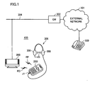
- FIG. 1 An entire configuration including a television system 100 according to an embodiment of the present invention will be described with reference to Fig. 1 .
- Television system 100 includes a television device 200 and a remote controller device 250.
- TV device 200 is connected to a home network 304, and is configured to allow connection onto an external network 301 via a gateway (GW) 302.
- Home network 304 is a wired network for interconnection of respective devices to implement data transmission according to, for example, the Ethernet standard.
- Television device 200 generates a video signal and a broadcast audio signal from a broadcast signal received via an antenna (not shown) or the like to display images according to the video signal on a screen thereof, and to output the broadcast audio signal from its own speaker or to transmit the broadcast audio signal to remote controller device 250 by means of a radio wave RD.
- the broadcast signal may be transmitted via home network 304.
- Transmission of an audio signal between television device 200 and remote controller device 250 is realized according to a predetermined transmission standard.
- a wireless LAN Local Area Network
- IEEE Institute of Electrical and Electronics Engineers, Inc.
- 802.11a/b/g/n/j for example
- Wi-Fi wireless LAN
- Bluetooth trademark
- IEEE802.15.1 trademark
- UMB defined as IEEE802.15.3a
- a radio wave in the range of 2.4 GHz, 5.2 GHz, or the like is employed for such audio transmission.
- Television device 200 receives a operation command according to an operation made by the user, transmitted from remote controller device 250 via infrared radiation RF to execute channel selection, volume adjustment, and the like according to the operation command.
- Television device 200 particularly includes a telephone function to engage in a conversation with a conversation party.
- television device 200 establishes communication with a conversation party by means of the VoIP (Voice over Internet Protocol) technique utilizing an Internet protocol.
- VoIP Voice over Internet Protocol
- sound associated with conversation is transmitted in the form of a packet.
- television device 200 has a telephone function based on the Internet protocol, the telephone set of the conversation party is not restricted to an IP telephone set. In other words, only an external network 301 is required between television device 200 and telephone set 320, and connection with a conventional telephone is allowed by providing a telephone exchange or the like on the path.
- television device 200 transmits the incoming voice from a conversation party to remote controller device 250, and sends an outgoing voice received from remote controller device 250 to the conversation party. Details will be described afterwards.
- Remote controller device 250 generates an operation command according to an operation made by the user to transmit the command to television device 200 via infrared radiation RF. Transmission of an operation command by infrared radiation RF is mono-directional transmission from remote controller device 250 to television device 200.
- Remote controller device 250 has a jack J1 to which a headset 306 can be connected.
- Jack J1 includes at least an external output path from remote controller device 250, and an input path to remote controller device 250.
- Remote controller device 250 outputs an audio signal received from television device 200 outside the device via jack J1, and transmits an audio signal input via jack J1 to television device 200.
- Headset 306 is an example of an audio input/output device, and includes a speaker to output sound according to an input audio signal, and a microphone 310 to generate an audio signal according to input sound. Headset 306 is fitted on the user's head. Sound corresponding to the audio signal output from jack J1 is emitted from speaker 308 located near the user's ear or in the neighborhood thereof. Microphone 310 located near the user's mouth or in the neighborhood thereof generates an audio signal from the user's voice to provide the generated audio signal to jack J1.
- the user can listen to the broadcast sound at a location remote from television device 200 by means of remote controller device 250 and headset 306 connected thereto, and have a conversation with another party using the telephone function of television device 200.
- the broadcast audio signal generated at television device 200 is transmitted to remote controller device 250 to be output from speaker 308 of headset 306 via jack J1.
- the incoming audio signal from the conversation party is transmitted from television device 200 to remote controller device 250, and output from speaker 308 of headset 306 via jack J1.
- the user's voice is converted into an outgoing audio signal at microphone 310 of headset 306 to be transmitted from remote controller device 250 to television device 200, and then to the conversation party.
- a configuration of television device 200 and remote controller device 250 to realize the operation set forth above will be described in further detail hereinafter.
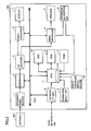
- television device 200 includes a broadcast signal receiver 1, a descrambler 2, an AV (Audio Visual) decoder 3, an audio processor 4, a speaker 5, a video processor 6, a display 7, a network interface (IF) unit, an operation input unit 9, remote controller optical receiver 10, a CPU (Central Processing Unit) 11, a RAM (Random Access Memory) 12, a ROM (Read Only Memory) 13, a transmission and reception unit 14, and an OSD (On Screen Display) unit 16.
- Broadcast signal receiver 1 extracts a signal corresponding to a selected channel from the broadcast signal received via antenna ANT, and provides to descrambler 2 a signal (for example, intermediate frequency signal) having the carrier wave removed from the extracted signal.
- a signal for example, intermediate frequency signal
- Descrambler 2 applies a descrambling process and/or decoding process on the scrambled digital signal from broadcast signal receiver 1.
- the processed signal is provided to AV decoder 3.
- descrambler 2 can directly provide the signal to AV decoder 3 without any processing thereon.
- AV decoder 3 generates a video signal and a broadcast audio signal based on the signal output from descrambler 2. AV decoder 3 outputs the generated video signal to video processor 6, and the generated broadcast audio signal to audio processor 4.
- Audio processor 4 receives the broadcast audio signal from AV decoder 3, and obtains an incoming audio signal from a conversation party via CPU 11 that will be described afterwards. Audio processor 4 responds to a command from CPU 11 to selectively amplify at least one of the broadcast audio signal and incoming audio signal for output to speaker 5.
- Speaker 5 is arranged, for example, at both side surfaces of television device 200 to generate sound according to the amplified signal from audio processor 4.
- speaker 5 is formed including a diaphragm (for example, paper corn) that vibrates according to an audio signal applied from audio processor 4, and generates sound by aerial vibration caused by vibration of the diaphragm.
- a diaphragm for example, paper corn
- Video processor 6 drives display 7 such that video according to the video signal from AV decoder 3 is displayed. Specifically, video processor 6 sequentially outputs color information of each pixel in synchronization with a predetermined scanning clock.
- Display 7 is a unit to display video, and is formed of a liquid crystal display (LCD), plasma display, or project type display.
- LCD liquid crystal display
- plasma display plasma display
- project type display project type display
- Network interface unit 8 is connected to home network 304 to receive and provide to CPU 11 or a bus BUS a data packet on home network 304, and to send the data applied from CPU 11 or bus BUS to home network 304.
- Operation input unit 9 is formed of a key button and the like, provided at the surface of the main body of television device 200 to provide a command according to an operation made by the user to CPU 11.
- Remote controller optical receiver 10 receives infrared radiation RF transmitted from remote controller device 250, which is decoded into an operation command for output to CPU 11.
- CPU 11 is a control device responsive to a command from operation input unit 9 or remote controller optical receiver 10 to control respective elements constituting television device 200.
- CPU 11 implements an IP telephone function unit 11A by execution of a program prestored in ROM 13 and the like.
- IP telephone function unit 11A executes a calling process to a conversation party according to an operation made by the user, or an incoming call process from a conversation party to establish line connection with the conversation party. IP telephone function unit 11A transmits an incoming audio signal received from the conversation party to audio processor 4 via bus BUS, and sends an outgoing audio signal from transmission and reception unit 14 to the conversation party.
- RAM 12 is connected to CPU 11, and functions as a work memory to store temporary data and the like that is generated during a process executed by CPU 11.
- ROM 13 has a program that is to be executed by CPU 11 stored in advance, and is read out by CPU 11 when television device 200 is activated.
- Transmission and reception unit 14 functions to transmit and receive an audio signal to/from remote controller device 250 ( Fig. 1 ).
- Transmission and reception unit 14 transmits a radio wave that is modulated from the audio signal received from audio processor 4, and demodulates the radio wave received from remote controller device 250 to an audio signal for transmission to CPU 11.
- Transmission and reception unit 14 may be incorporated in television device 200, or configured to allow a unit corresponding to transmission and reception unit 14 to be externally provided, as necessary.
- OSD unit 16 responds to a control command from CPU 11 to generate video data to display a user interface screen on display 7.
- the video data is provided to video processor 6 via CPU 11.
- CPU 11 responds to a user operation applied through operation input unit 9 or remote controller optical receiver 10, or responds to occurrence of an incoming call process by IP telephone function unit 11A to select either "watching mode” or "telephone mode".
- CPU 11 When in a "watching mode" selected state, CPU 11 cuts off the output of a incoming audio signal from IP telephone function unit 11A to audio processor 4 to disable transmission from television device 200 to remote controller device 250. In a "watching mode", only the broadcast audio signal from audio processor 4 is output.
- CPU 11 When in a "telephone mode" selected state, CPU 11 provides a control command to audio processor 4 to cut off the output of a broadcast audio signal from audio processor 4 to disable transmission from television device 200 to remote controller device 250. In a telephone mode, only an incoming audio signal from audio processor 4 is output.
- mixture of broadcast audio into the incoming sound during conversation can be prevented.
- a conversation can be made appropriately even if a telephone call is received when the user is watching television.
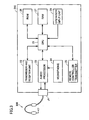
- remote controller device 250 includes a CPU 21, a transmission and reception unit 22, an audio processor 23, a microphone 24, a remote controller transmitter 25, a ROM 26, a RAM 27, an operation input unit 28, and a jack J1.
- CPU 21 is a control device to control respective elements constituting remote controller device 250.
- Transmission and reception unit 22 serves to transmit/receive an audio signal to/from television device 200 ( Fig. 1 ), and transmits a radio wave that is modulated from an audio signal received from audio processor 4 via CPU 21, and demodulate a radio wave received from television device 200 to an audio signal for transmission to audio processor 23 via CPU 21.
- Audio processor 23 is connected to jack J1 and CPU 21, and responds to a control command from CPU 21 to convert a digitized audio signal received at transmission and reception unit 22 to an analog audio signal for output via jack J1. Audio processor 23 also digitizes an analog audio signal input from headset 306 via jack J1 for output to transmission and reception unit 22. Alternatively, audio processor 23 may digitize an analog audio signal applied from microphone 24 of remote controller device 250 for output to transmission and reception unit 22.
- Audio processor 23 determines whether headset 306 is connected to jack J1 or not based on an output audio signal towards jack J1 or an input audio signal from jack J1. For example, audio processor 23 determines whether headset 306 is in a connection state or non-connection state based on the level of the current value (or impedance value) of the output audio signal.
- Microphone 24 is disposed at the surface area or the like of remote controller device 250 to collect the user's voice or sound to generate an audio signal according to the collected sound. Microphone 24 provides the generated audio signal to audio processor 23.
- remote controller transmitter 25 In response to receiving an operation command via CPU 21 from operation input unit 28 caused by an operation made by the user, remote controller transmitter 25 emits modulated infrared radiation RF according to the operation command.
- Infrared radiation RF has low power consumption as compared to a radio wave corresponding to transmission/reception of an audio signal, and is emitted only when an operation is made by the user.
- a program or the like executed at CPU 21 is prestored in ROM 26, and read out by CPU 22 when remote controller device 250 is activated.
- RAM 27 is connected to CPU 21, and functions as a work memory in which temporary data generated during the process executed at CPU 21 is stored.
- Operation input unit 28 functions as a user interface that accepts an operation made by the user, and is provided at the surface region of the body of remote controller device 250.
- operation input unit 28 is formed of a key button and the like.
- a usage manner of television system 100 according to an embodiment of the present invention will be described in detail hereinafter.
- Fig. 4A represents the state where headset 306 is connected to remote controller device 250.
- Fig. 4B represents the state where headset 306 is not connected to remote controller device 250.
- audio processor 23 ( Fig. 3 ) of remote controller device 250 determines that headset 306 is connected, and provides the determination result to CPU 21 ( Fig. 3 ).
- CPU 21 provides the incoming audio signal, received at transmission and reception unit 22 ( Fig. 3 ) from television device 200, to audio processor 23.
- Audio processor 23 provides the incoming audio signal to headset 306 via jack J1. Then, the incoming sound is output from speaker 308.
- the voice of the user is converted into an incoming audio signal at microphone 301 of headset 306 to be provided to remote controller device 250 via jack J1.
- the relevant incoming audio signal is provided from audio processor 23 to transmission and reception unit 22 ( Fig. 3 ) via CPU 21 to be transmitted to television device 200.
- Radio wave RD includes the incoming audio signal transmitted from television device 200 to remote controller device 250, and the outgoing audio signal transmitted from remote controller device 250 to television device 200.
- audio processor 23 ( Fig. 3 ) of remote controller device 250 determines that headset 306 is not connected, and provides this determination result to CPU 21 ( Fig. 3 ).
- CPU 21 transmits a notification of a non-connection state to television device 200 via transmission and reception unit 22 ( Fig. 3 ).
- CPU 11 ( Fig. 2 ) of television device 200 provides a control command to audio processor 4 ( Fig. 2 ) to cause the incoming sound to be output from speaker 5 of television device 200.
- the voice of the user is converted into an incoming audio signal at microphone 310 of headset 306 to be provided to remote controller device 250 via jack J1.
- the relevant incoming audio signal is provided to transmission and reception unit 22 ( Fig. 3 ) via CPU 21 from audio processor 23 of remote controller device 250 to be transmitted to television device 200.
- Radio wave RD includes the outgoing audio signal transmitted from remote controller device 250 to television device 200.
- television device 200 when the user operates remote controller device 250 to select the watching mode, television device 200 responds to this selection signal to generate a video signal and broadcast audio signal from the broadcast signal corresponding to the selected channel.
- Television device 200 displays video corresponding to the generated video signal on its screen, and transmits the broadcast audio signal to remote controller device 250 by means of radio wave RD.
- Audio processor 23 ( Fig. 3 ) of remote controller device 250 provides the broadcast audio signal to headset 306 via jack J1. Then, the broadcast sound is output from speaker 308.
- Radio wave RD includes the broadcast audio signal transmitted from television device 200 to remote controller device 250.
- Fig. 6A represents an example of the user interface display during a dialing operation.
- Fig. 6B represents an example of the user interface display when in a conversation mode.
- CPU 11 ( Fig. 2 ) of television device 200 provides a control command to OSD unit 16 ( Fig. 2 ).
- OSD unit 16 provides to video processor 6 ( Fig. 2 ) the video data to display a picture of remote controller device 250.
- video processor 6 provides the video data from OSD unit 16 in an overlapping manner on the image received in the watching mode for display 7.
- a screen display R1 indicating a dial input acceptance state from remote controller device 250 is displayed, overlapping on the picture of the displayed channel.
- a display to allow confirmation of the operation made by the user can be provided at screen display R1.
- a dynamic display of a corresponding button being depressed or changing the display color of the corresponding button can be provided at screen display R1.
- a text display R2 such as "IP telephone" indicating that a telephone mode has been selected may be displayed.
- an input number display R3 representing the entered number in time series is provided.
- the calling button not shown
- the number train displayed at input number display R3 will appear in a blinking manner to notify the user that a calling process is being executed.
- an icon R4 indicating that a conversation mode is currently effected is displayed, as shown in Fig. 6B .
- icon R4 disappears, and the screen returns to a picture display of a watching mode.
- CPU 11 corresponds to "control unit”
- broadcast signal reception unit 1 corresponds to “broadcast reception unit”
- IP telephone function unit 11A corresponds to "IP telephone function unit”
- transmission and reception unit 14 corresponds to "first transmission and reception unit”
- headset 102 correspond to "audio input/output device”
- transmission and reception unit 22 corresponds to "second transmission and reception unit”
- audio processor 23 corresponds to "audio processor”.
- the incoming sound received at television device 200 is transmitted to remote controller device 250 via a radio wave, and sound is output towards the user from speaker 308 of headset 306 connected to remote controller device 250.
- the outgoing voice issued by the user is transmitted to television device 200 from remote controller device 250 via a radio signal and is sent to the conversation party. Therefore, the user can use the telephone at an arbitrary position within a range of distance that allows radio wave reception between television device 200 and remote controller device 250.
- the user can select a channel of television device 200 by means of remote controller device 250, and also listen to the broadcast sound from television device 200 by the same headset 306.
- remote controller device 250 By carrying remote controller device 250, the user can watch a television broadcast and have a telephone conversation at an arbitrary position. Therefore, a television system of favorable usability can be implemented.
- an arbitrary headset can be attached to remote controller device 250. Therefore, the user can select and use an optimum headset from the standpoints of sound quality, weight, design, fitting, and the like, corresponding to the manner of usage. Thus, the versatility is high.
- an operation command is transmitted from remote controller device 250 via infrared radiation RF while an audio signal is transmitted via radio wave RD. Therefore, infrared radiation RF that is lower in power consumption is emitted when the remote controller device is used based on only the conventional function, i.e. when headset 306 connected to remote controller device 250 is not used. Therefore, power consumption at remote controller device 250 can be suppressed. Accordingly, the number of batteries or the like to be loaded in remote controller device 250 can be reduced to allow reduction in size and weight.
Landscapes
- Engineering & Computer Science (AREA)
- Signal Processing (AREA)
- Multimedia (AREA)
- Human Computer Interaction (AREA)
- General Engineering & Computer Science (AREA)
- Telephonic Communication Services (AREA)
- Details Of Television Systems (AREA)
- Selective Calling Equipment (AREA)
Applications Claiming Priority (1)
| Application Number | Priority Date | Filing Date | Title |
|---|---|---|---|
| JP2006352309A JP2008166980A (ja) | 2006-12-27 | 2006-12-27 | テレビジョンシステムおよびリモコン装置 |
Publications (2)
| Publication Number | Publication Date |
|---|---|
| EP1940156A2 true EP1940156A2 (de) | 2008-07-02 |
| EP1940156A3 EP1940156A3 (de) | 2009-08-05 |
Family
ID=39247237
Family Applications (1)
| Application Number | Title | Priority Date | Filing Date |
|---|---|---|---|
| EP07024834A Ceased EP1940156A3 (de) | 2006-12-27 | 2007-12-20 | Fernsehsystem mit installierter Telefonfunktion und darauf gerichtete Fernsteuerungsvorrichtung |
Country Status (4)
| Country | Link |
|---|---|
| US (1) | US20080157998A1 (de) |
| EP (1) | EP1940156A3 (de) |
| JP (1) | JP2008166980A (de) |
| CN (1) | CN101212556A (de) |
Cited By (8)
| Publication number | Priority date | Publication date | Assignee | Title |
|---|---|---|---|---|
| WO2010026190A1 (en) * | 2008-09-05 | 2010-03-11 | Skype Limited | Communication system and method |
| US8407749B2 (en) | 2008-09-05 | 2013-03-26 | Skype | Communication system and method |
| US8413199B2 (en) | 2008-09-05 | 2013-04-02 | Skype | Communication system and method |
| US8421839B2 (en) | 2008-09-05 | 2013-04-16 | Skype | Peripheral device for communication over a communications system |
| US8473994B2 (en) | 2008-09-05 | 2013-06-25 | Skype | Communication system and method |
| US8489691B2 (en) | 2008-09-05 | 2013-07-16 | Microsoft Corporation | Communication system and method |
| US8520050B2 (en) | 2008-09-05 | 2013-08-27 | Skype | Communication system and method |
| EP2579606A3 (de) * | 2011-10-07 | 2013-10-16 | Samsung Electronics Co., Ltd | Fernsteuerungsvorrichtung, Fernsteuerungsverfahren und Anzeigevorrichtung |
Families Citing this family (32)
| Publication number | Priority date | Publication date | Assignee | Title |
|---|---|---|---|---|
| US20040003136A1 (en) * | 2002-06-27 | 2004-01-01 | Vocollect, Inc. | Terminal and method for efficient use and identification of peripherals |
| US8572251B2 (en) | 2008-11-26 | 2013-10-29 | Microsoft Corporation | Hardware acceleration for remote desktop protocol |
| US9122317B2 (en) | 2009-08-06 | 2015-09-01 | Kyocera Corporation | Electronic device and screen display method |
| JP5528058B2 (ja) * | 2009-10-28 | 2014-06-25 | 京セラ株式会社 | 電子機器 |
| GB2475237B (en) * | 2009-11-09 | 2016-01-06 | Skype | Apparatus and method for controlling communication signalling and media |
| GB2479180B (en) | 2010-03-31 | 2016-06-01 | Skype | System of user devices |
| GB201005465D0 (en) * | 2010-03-31 | 2010-05-19 | Skype Ltd | Television set |
| GB201005458D0 (en) | 2010-03-31 | 2010-05-19 | Skype Ltd | Media appliance |
| US8508575B2 (en) | 2010-03-31 | 2013-08-13 | Sony Corporation | Television system, television set and method for operating a television system |
| GB201005454D0 (en) | 2010-03-31 | 2010-05-19 | Skype Ltd | Television apparatus |
| US8848934B2 (en) * | 2010-12-08 | 2014-09-30 | Skype | Controlling audio signals |
| US8963982B2 (en) | 2010-12-31 | 2015-02-24 | Skype | Communication system and method |
| US10404762B2 (en) | 2010-12-31 | 2019-09-03 | Skype | Communication system and method |
| US10291660B2 (en) | 2010-12-31 | 2019-05-14 | Skype | Communication system and method |
| US9717090B2 (en) | 2010-12-31 | 2017-07-25 | Microsoft Technology Licensing, Llc | Providing notifications of call-related services |
| JP5672034B2 (ja) | 2011-02-03 | 2015-02-18 | ソニー株式会社 | 制御装置、制御装置の音声切替え方法およびプログラム |
| CN102281296A (zh) * | 2011-08-09 | 2011-12-14 | 上海交通大学 | 一种面向老年人的电视可视电话系统 |
| US9019336B2 (en) | 2011-12-30 | 2015-04-28 | Skype | Making calls using an additional terminal |
| CN102739864B (zh) * | 2012-06-15 | 2015-08-19 | 惠州Tcl移动通信有限公司 | 实现电视无线耳机功能的方法及无线通讯设备 |
| CN103716664A (zh) * | 2012-09-28 | 2014-04-09 | 珠海扬智电子科技有限公司 | 多媒体系统及其控制方法 |
| GB201301452D0 (en) | 2013-01-28 | 2013-03-13 | Microsoft Corp | Providing notifications of call-related services |
| US9100743B2 (en) | 2013-03-15 | 2015-08-04 | Vocollect, Inc. | Method and system for power delivery to a headset |
| JP5914945B2 (ja) * | 2013-12-10 | 2016-05-11 | パナソニックIpマネジメント株式会社 | 電話装置、電話システム、及び制御方法 |
| US9641925B2 (en) * | 2014-01-02 | 2017-05-02 | Zippy Technology Corp. | Headphone wireless expansion device capable of switching among multiple targets and voice control method thereof |
| US20150295783A1 (en) * | 2014-04-10 | 2015-10-15 | Screenovate Technologies Ltd. | Method for real-time multimedia interface management sensor data |
| KR102386309B1 (ko) * | 2015-06-04 | 2022-04-14 | 삼성전자주식회사 | 전자 장치 및 전자 장치에서의 입출력 제어 방법 |
| CN104918087B (zh) * | 2015-07-03 | 2019-03-26 | 成都怡云科技有限公司 | 一种用于智能酒店机顶盒的遥控器 |
| CN104918089B (zh) * | 2015-07-03 | 2018-10-19 | 成都怡云科技有限公司 | 具有语音控制功能的基于云服务器的智慧酒店服务系统 |
| CN105792016A (zh) * | 2016-04-22 | 2016-07-20 | 合肥惠科金扬科技有限公司 | 一种具备门禁功能的电视系统 |
| CN106488281A (zh) * | 2016-10-26 | 2017-03-08 | Tcl集团股份有限公司 | 一种电视音频的播放方法及控制系统、电视、通信系统 |
| CN109361890A (zh) * | 2018-12-12 | 2019-02-19 | 达州市志向科技外包服务有限公司 | 一种视频通话系统 |
| CN112017693B (zh) * | 2019-05-30 | 2023-11-24 | 腾讯科技(深圳)有限公司 | 一种音频质量评估方法及装置 |
Citations (5)
| Publication number | Priority date | Publication date | Assignee | Title |
|---|---|---|---|---|
| US6359636B1 (en) | 1995-07-17 | 2002-03-19 | Gateway, Inc. | Graphical user interface for control of a home entertainment system |
| US20020102949A1 (en) * | 2001-01-17 | 2002-08-01 | Sherman Langer | Remote control having an audio port |
| US20020149705A1 (en) * | 2001-04-12 | 2002-10-17 | Allen Paul G. | Contact list for a hybrid communicator/remote control |
| US20030041331A1 (en) * | 2001-08-21 | 2003-02-27 | Allen Paul G. | System and method for mitigating interruptions during television viewing |
| US20060040638A1 (en) | 2004-08-17 | 2006-02-23 | Mcquaide Arnold Jr | Hand-held remote personal communicator & controller |
Family Cites Families (6)
| Publication number | Priority date | Publication date | Assignee | Title |
|---|---|---|---|---|
| US6151490A (en) * | 1996-12-02 | 2000-11-21 | Douglas G. Brown | Methods and systems for providing audio and video telephone communications using a personal computer and a television |
| US6628964B1 (en) * | 2000-07-20 | 2003-09-30 | International Business Machines Corporation | Combination cordless telephone and remote control for entertainment equipment |
| AU2001261268A1 (en) * | 2000-09-29 | 2002-04-15 | Digeo, Inc. | Systems, methods, and devices for audio capture and telecommunication |
| JP2005039540A (ja) * | 2003-07-15 | 2005-02-10 | Sony Corp | テレビジョン受像機 |
| JP2006109094A (ja) * | 2004-10-05 | 2006-04-20 | Nec Software Kyushu Ltd | 遠隔制御装置、遠隔制御システム、及び、遠隔制御方法 |
| EP1813090A2 (de) * | 2004-10-25 | 2007-08-01 | Nokia Corporation | Verbesserungen in bezug auf elektronische einrichtungen für audio-/video-plugs |
-
2006
- 2006-12-27 JP JP2006352309A patent/JP2008166980A/ja active Pending
-
2007
- 2007-12-13 US US11/956,206 patent/US20080157998A1/en not_active Abandoned
- 2007-12-20 EP EP07024834A patent/EP1940156A3/de not_active Ceased
- 2007-12-27 CN CNA2007103061702A patent/CN101212556A/zh active Pending
Patent Citations (5)
| Publication number | Priority date | Publication date | Assignee | Title |
|---|---|---|---|---|
| US6359636B1 (en) | 1995-07-17 | 2002-03-19 | Gateway, Inc. | Graphical user interface for control of a home entertainment system |
| US20020102949A1 (en) * | 2001-01-17 | 2002-08-01 | Sherman Langer | Remote control having an audio port |
| US20020149705A1 (en) * | 2001-04-12 | 2002-10-17 | Allen Paul G. | Contact list for a hybrid communicator/remote control |
| US20030041331A1 (en) * | 2001-08-21 | 2003-02-27 | Allen Paul G. | System and method for mitigating interruptions during television viewing |
| US20060040638A1 (en) | 2004-08-17 | 2006-02-23 | Mcquaide Arnold Jr | Hand-held remote personal communicator & controller |
Cited By (12)
| Publication number | Priority date | Publication date | Assignee | Title |
|---|---|---|---|---|
| WO2010026190A1 (en) * | 2008-09-05 | 2010-03-11 | Skype Limited | Communication system and method |
| GB2463108B (en) * | 2008-09-05 | 2012-08-29 | Skype | Communication system and method |
| US8407749B2 (en) | 2008-09-05 | 2013-03-26 | Skype | Communication system and method |
| US8413199B2 (en) | 2008-09-05 | 2013-04-02 | Skype | Communication system and method |
| US8421839B2 (en) | 2008-09-05 | 2013-04-16 | Skype | Peripheral device for communication over a communications system |
| US8473994B2 (en) | 2008-09-05 | 2013-06-25 | Skype | Communication system and method |
| US8489691B2 (en) | 2008-09-05 | 2013-07-16 | Microsoft Corporation | Communication system and method |
| US8520050B2 (en) | 2008-09-05 | 2013-08-27 | Skype | Communication system and method |
| US8866628B2 (en) | 2008-09-05 | 2014-10-21 | Skype | Communication system and method |
| US9128592B2 (en) | 2008-09-05 | 2015-09-08 | Skype | Displaying graphical representations of contacts |
| US9654726B2 (en) | 2008-09-05 | 2017-05-16 | Skype | Peripheral device for communication over a communications system |
| EP2579606A3 (de) * | 2011-10-07 | 2013-10-16 | Samsung Electronics Co., Ltd | Fernsteuerungsvorrichtung, Fernsteuerungsverfahren und Anzeigevorrichtung |
Also Published As
| Publication number | Publication date |
|---|---|
| JP2008166980A (ja) | 2008-07-17 |
| EP1940156A3 (de) | 2009-08-05 |
| CN101212556A (zh) | 2008-07-02 |
| US20080157998A1 (en) | 2008-07-03 |
Similar Documents
| Publication | Publication Date | Title |
|---|---|---|
| US20080157998A1 (en) | Television system with installed telephone function, and remote controller device directed thereto | |
| US20080129888A1 (en) | Television device with telephone function, and television system including such television device | |
| EP2432203B1 (de) | Empfangs- und Sendeverfahren eines mobilen TV-Telefons und mobiles TV-Telefonendgerät | |
| US8639298B2 (en) | Mobile phone and incoming alerting system | |
| JP2007150473A (ja) | テレビ放送受信装置及びドアホン装置及びインターホンシステム | |
| JP2006523411A (ja) | 遠隔電子装置からの情報を表示するための方法、装置及びシステム | |
| KR100939914B1 (ko) | Ip셋톱박스와 음성 송수신 리모콘을 이용한 멀티미디어 시스템 | |
| US7266834B1 (en) | Sharing functions between a television-based information appliance and remote control devices | |
| JP2004080289A (ja) | 通信装置 | |
| US20070120962A1 (en) | Cordless IP video phone system | |
| JP3781744B2 (ja) | 無線通信端末装置の音声出力方法、無線通信端末装置 | |
| KR100928253B1 (ko) | 이동통신 단말기의 vod 데이터 전송방법 및 이러한 방법을 구현하는 이동통신 단말기 | |
| KR20040038003A (ko) | 이동통신 단말기의 착신정보를 알려주기 위한 전자기기와그를 이용한 착신정보 알림 방법 | |
| KR101051382B1 (ko) | 티브이를 이용한 이동통신 서비스 제공 장치 및 그 방법 | |
| KR101044064B1 (ko) | 리모컨 겸용 인터넷 전화기를 일체로 구비한 셋탑박스장치 및 서비스 방법 | |
| KR100630101B1 (ko) | 휴대단말기에서 다기능을 구비한 휴대용 홈 씨어터 제어방법 | |
| JP3179430B2 (ja) | 携帯電話機 | |
| KR20020028437A (ko) | 화상전화기의 영상표시 텔레비젼 장치 및 영상표시방법 | |
| JP2006148524A (ja) | 携帯無線装置 | |
| KR100282060B1 (ko) | 텔레비전을 사용한 전화기의 자동 응답 전환 방법 | |
| KR200178713Y1 (ko) | 인터넷 텔레비젼 셋탑박스 | |
| KR200233492Y1 (ko) | 전화기능이 구비된 디지털 위성방송수신기 | |
| KR19990043044A (ko) | 인터넷 텔레비전수상기에서 지정수신자 표시방법 및 그 장치 | |
| JP2003101713A (ja) | ファクシミリ電話装置 | |
| JPH065267U (ja) | 携帯用無線電話機 |
Legal Events
| Date | Code | Title | Description |
|---|---|---|---|
| PUAI | Public reference made under article 153(3) epc to a published international application that has entered the european phase |
Free format text: ORIGINAL CODE: 0009012 |
|
| AK | Designated contracting states |
Kind code of ref document: A2 Designated state(s): AT BE BG CH CY CZ DE DK EE ES FI FR GB GR HU IE IS IT LI LT LU LV MC MT NL PL PT RO SE SI SK TR |
|
| AX | Request for extension of the european patent |
Extension state: AL BA HR MK RS |
|
| PUAL | Search report despatched |
Free format text: ORIGINAL CODE: 0009013 |
|
| AK | Designated contracting states |
Kind code of ref document: A3 Designated state(s): AT BE BG CH CY CZ DE DK EE ES FI FR GB GR HU IE IS IT LI LT LU LV MC MT NL PL PT RO SE SI SK TR |
|
| AX | Request for extension of the european patent |
Extension state: AL BA HR MK RS |
|
| RIC1 | Information provided on ipc code assigned before grant |
Ipc: H04M 1/725 20060101ALI20090630BHEP Ipc: H04N 7/14 20060101ALI20090630BHEP Ipc: H04N 5/445 20060101AFI20080409BHEP |
|
| 17P | Request for examination filed |
Effective date: 20100204 |
|
| AKX | Designation fees paid |
Designated state(s): AT BE BG CH CY CZ DE DK EE ES FI FR GB GR HU IE IS IT LI LT LU LV MC MT NL PL PT RO SE SI SK TR |
|
| 17Q | First examination report despatched |
Effective date: 20100406 |
|
| STAA | Information on the status of an ep patent application or granted ep patent |
Free format text: STATUS: THE APPLICATION HAS BEEN REFUSED |
|
| 18R | Application refused |
Effective date: 20111217 |