EP1942020B1 - Aufhängungssystem für fahrzeug - Google Patents
Aufhängungssystem für fahrzeug Download PDFInfo
- Publication number
- EP1942020B1 EP1942020B1 EP06822204A EP06822204A EP1942020B1 EP 1942020 B1 EP1942020 B1 EP 1942020B1 EP 06822204 A EP06822204 A EP 06822204A EP 06822204 A EP06822204 A EP 06822204A EP 1942020 B1 EP1942020 B1 EP 1942020B1
- Authority
- EP
- European Patent Office
- Prior art keywords
- coils
- electromagnetic
- coil
- vehicle
- vibration
- Prior art date
- Legal status (The legal status is an assumption and is not a legal conclusion. Google has not performed a legal analysis and makes no representation as to the accuracy of the status listed.)
- Not-in-force
Links
Images


Classifications
-
- F—MECHANICAL ENGINEERING; LIGHTING; HEATING; WEAPONS; BLASTING
- F16—ENGINEERING ELEMENTS AND UNITS; GENERAL MEASURES FOR PRODUCING AND MAINTAINING EFFECTIVE FUNCTIONING OF MACHINES OR INSTALLATIONS; THERMAL INSULATION IN GENERAL
- F16F—SPRINGS; SHOCK-ABSORBERS; MEANS FOR DAMPING VIBRATION
- F16F15/00—Suppression of vibrations in systems; Means or arrangements for avoiding or reducing out-of-balance forces, e.g. due to motion
- F16F15/02—Suppression of vibrations of non-rotating, e.g. reciprocating systems; Suppression of vibrations of rotating systems by use of members not moving with the rotating systems
- F16F15/03—Suppression of vibrations of non-rotating, e.g. reciprocating systems; Suppression of vibrations of rotating systems by use of members not moving with the rotating systems using magnetic or electromagnetic means
-
- B—PERFORMING OPERATIONS; TRANSPORTING
- B60—VEHICLES IN GENERAL
- B60G—VEHICLE SUSPENSION ARRANGEMENTS
- B60G17/00—Resilient suspensions having means for adjusting the spring or vibration-damper characteristics, for regulating the distance between a supporting surface and a sprung part of vehicle or for locking suspension during use to meet varying vehicular or surface conditions, e.g. due to speed or load
- B60G17/06—Characteristics of dampers, e.g. mechanical dampers
-
- B—PERFORMING OPERATIONS; TRANSPORTING
- B60—VEHICLES IN GENERAL
- B60G—VEHICLE SUSPENSION ARRANGEMENTS
- B60G2202/00—Indexing codes relating to the type of spring, damper or actuator
- B60G2202/40—Type of actuator
- B60G2202/42—Electric actuator
-
- B—PERFORMING OPERATIONS; TRANSPORTING
- B60—VEHICLES IN GENERAL
- B60G—VEHICLE SUSPENSION ARRANGEMENTS
- B60G2400/00—Indexing codes relating to detected, measured or calculated conditions or factors
- B60G2400/10—Acceleration; Deceleration
- B60G2400/102—Acceleration; Deceleration vertical
-
- B—PERFORMING OPERATIONS; TRANSPORTING
- B60—VEHICLES IN GENERAL
- B60G—VEHICLE SUSPENSION ARRANGEMENTS
- B60G2400/00—Indexing codes relating to detected, measured or calculated conditions or factors
- B60G2400/10—Acceleration; Deceleration
- B60G2400/104—Acceleration; Deceleration lateral or transversal with regard to vehicle
-
- B—PERFORMING OPERATIONS; TRANSPORTING
- B60—VEHICLES IN GENERAL
- B60G—VEHICLE SUSPENSION ARRANGEMENTS
- B60G2400/00—Indexing codes relating to detected, measured or calculated conditions or factors
- B60G2400/10—Acceleration; Deceleration
- B60G2400/106—Acceleration; Deceleration longitudinal with regard to vehicle, e.g. braking
-
- B—PERFORMING OPERATIONS; TRANSPORTING
- B60—VEHICLES IN GENERAL
- B60G—VEHICLE SUSPENSION ARRANGEMENTS
- B60G2400/00—Indexing codes relating to detected, measured or calculated conditions or factors
- B60G2400/20—Speed
- B60G2400/204—Vehicle speed
-
- B—PERFORMING OPERATIONS; TRANSPORTING
- B60—VEHICLES IN GENERAL
- B60G—VEHICLE SUSPENSION ARRANGEMENTS
- B60G2400/00—Indexing codes relating to detected, measured or calculated conditions or factors
- B60G2400/25—Stroke; Height; Displacement
- B60G2400/252—Stroke; Height; Displacement vertical
-
- B—PERFORMING OPERATIONS; TRANSPORTING
- B60—VEHICLES IN GENERAL
- B60G—VEHICLE SUSPENSION ARRANGEMENTS
- B60G2400/00—Indexing codes relating to detected, measured or calculated conditions or factors
- B60G2400/40—Steering conditions
- B60G2400/41—Steering angle
-
- B—PERFORMING OPERATIONS; TRANSPORTING
- B60—VEHICLES IN GENERAL
- B60G—VEHICLE SUSPENSION ARRANGEMENTS
- B60G2500/00—Indexing codes relating to the regulated action or device
- B60G2500/10—Damping action or damper
-
- B—PERFORMING OPERATIONS; TRANSPORTING
- B60—VEHICLES IN GENERAL
- B60G—VEHICLE SUSPENSION ARRANGEMENTS
- B60G2800/00—Indexing codes relating to the type of movement or to the condition of the vehicle and to the end result to be achieved by the control action
- B60G2800/01—Attitude or posture control
- B60G2800/012—Rolling condition
-
- B—PERFORMING OPERATIONS; TRANSPORTING
- B60—VEHICLES IN GENERAL
- B60G—VEHICLE SUSPENSION ARRANGEMENTS
- B60G2800/00—Indexing codes relating to the type of movement or to the condition of the vehicle and to the end result to be achieved by the control action
- B60G2800/01—Attitude or posture control
- B60G2800/014—Pitch; Nose dive
Definitions
- the above-described electromagnetic absorber is operable to generate the damping force by shortcircuiting a coil of the motor, in other words, by electrically connecting terminals of the motor outside the motor.
- Japanese Patent Application Publication JP-A-2003-223220 describes an electromagnetic suspension apparatus in which a damping forte is generated by shortcircuiting the coil of the motor when the electromagnetic suspension apparatus is out of control.
- Japanese Patent application Publication JP-A-2001-310736 which is considered as closest prior art forming the basis for the preamble of claim 1, discloses a technique of controlling the damping force in relation to a control for an electromagnetic suspension apparatus.
- the above-described problems are just a part of problems experienced in the system having the electromagnetic suspension apparatus, namely, the electromagnetic suspension system. Since the electromagnetic suspension system is still under development, the system suffers from various other problems including those described above. Accordingly, it is possible to improve the utility of the system by coping with any of the problems. In other words, there is much room for improvement in the electromagnetic suspension system.
- the present invention has been developed in the light of the situations. It is therefore an object of the invention to provide a suspension system for a vehicle having high utility.
- a suspension system for a vehicle to which the present invention is applied comprises four electromagnetic absorbers provided for respective four wheels of the vehicle, more specifically, four shock absorbers each of which includes a coil and a magnet and is operable to generate a damping force that depends on an electromotive force generated by a relative movement of the coil and the magnet.
- the vehicle suspension system according to the invention is defined in the appended claims.
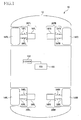
- Fig. 1 is a schematic view showing a vehicle equipped with a suspension system according to a first embodiment of the claimable invention.
- Fig. 2 is a view showing in more detail a structure of an electromagnetic absorber of the vehicle suspension system of the first embodiment.
- the electromagnetic absorber 30 When the wheel 14 and the vehicle body 12 move relative to each other in the vertical direction by an external force due to roughness or unevenness of the rod surface, the outer tube 50 and the inner tube 42 move relative to each other in the vertical direction, so that the coil spring 54 extends and contracts.
- the threaded rod 44 and the nut 46 move relative to each other in the axis direction, whereby the threaded rod 44 rotates, and the output shaft 36 of the motor 16 rotates.
- the rotor and the stator namely, the magnet and the coil, move relative to each other, so that an electromotive force is generated in the coil.
- the motor 16 functions as a generator.
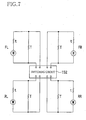
- the switching circuit 152 is configured such that all of the coils are normally placed in the connected state and such that, when it is judged that the vibration in any one of the vibration modes is being generated, the connection of the coils corresponding to the judged vibration mode is maintained while the other connections of the coils are cut off. More specifically described, where it is judged that the vibration in the first-diagonal-vibration mode is being generated, for instance, the switching circuit 152 in the modified suspension system is configured to cut off the connection associated with the coils FR and the connection associated with the coils RL and to maintain only the connection of the coils FL and RR, thereby increasing the current that passes through those two coils FL and RR.
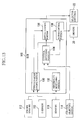
- the ECU 100 judges the state of the vehicle 10, specifically, the state of the vibration being generated in the vehicle, on the basis of the signals detected by various sensors such as the stroke sensors 112, and determines a force to be generated by each of the electromagnetic absorbers 30 provided for the respective four wheels, so as to suppress the vibration of the vehicle, changes in the vehicle posture, and unstable behavior of the vehicle and so as to stabilize the vehicle with respect to a steering operation, an accelerating operation, a braking operation and the like, by the vehicle operator. (An amount of the telescopic movement of each cylinder device 18 may be determined instead of the force to be generated by each electromagnetic absorber 30.) Further, the ECU 100 sends drive signals for driving the motors 16 to the respective drivers 20.
- An abnormality monitoring portion 132 monitors an occurrence of any abnormality that would hinder execution of the active control or the passive control, on the basis of the signals from various sensors 118.
- the electromagnetic absorber 30 having the damping-force generating device that employs the motor 16 of a rotary type.
- the present invention is applicable to an electromagnetic absorber having a damping-force generating device that employs a motor of a linear type.
- the electromagnetic absorber may be constructed as follows, for instance. A plurality of coils are disposed on an inner surface of the outer tube so as to arrange in the axial direction of the outer tube over a suitable axial length, and a plurality of permanent magnets are disposed on an outer surface of the inner tube so as to arrange in the axial direction of the inner tube over a suitable axial length.
- the outer tube and the inner tube are supported such that the outer and inner tubes are movable relative to each other in the vertical direction without contacting each other.
Landscapes
- Engineering & Computer Science (AREA)
- Mechanical Engineering (AREA)
- Physics & Mathematics (AREA)
- General Engineering & Computer Science (AREA)
- Electromagnetism (AREA)
- Acoustics & Sound (AREA)
- Aviation & Aerospace Engineering (AREA)
- Vehicle Body Suspensions (AREA)
Claims (3)
- Aufhängungssystem für ein Fahrzeug (10) mit:vier elektromagnetischen Stoßdämpfern (30FL, 30FR, 30RL, 30RR), die jeweils zu vier Rädern (14FL, 14FR, 14RL, 14RR) des Fahrzeugs gehören und von denen jeder Folgendes aufweist: (A) ein Teil (42) auf der gefederten Seite, das mit einem gefederten Abschnitt gekoppelt ist; (B) ein Teil (50) auf der ungefederten Seite, das mit einem ungefederten Abschnitt gekoppelt und dazu fähig ist, sich in Verbindung mit einer Relativbewegung des gefederten Abschnitts zu dem ungefederten Abschnitt relativ zu dem Teil auf der gefederten Seite zu bewegen; und (C) eine Vorrichtung (16FL, 16FR, 16RL, 16RR) zur Erzeugung einer Dämpfungskraft, die eine Spule und einen Magneten aufweist, die sich in Verbindung mit einer Relativbewegung des Teils auf der gefederten Seite zu dem Teil auf der ungefederten Seite relativ zueinander bewegen und dazu fähig sind, eine Dämpfungskraft bezüglich der Relativbewegung des Teils auf der gefederten Seite zu dem Teil auf der ungefederten Seite abhängig von einer elektromagnetischen Kraft zu erzeugen, die durch eine Relativbewegung der Spule und des Magneten erzeugt wird; undeiner Spulenverbindungsvorrichtung (88), die dazu aufgebaut ist, elektrisch Spulen der Vorrichtungen zur Erzeugung der Dämpfungskraft der jeweiligen vier elektromagnetischen Stoßdämpfer so zu verbinden, dass zwei geschlossene Schleifen gebildet werden, die jeweils zu zwei Radpaaren gehören, welche jeweils aus zwei diagonal zueinander angeordneten der vier Räder bestehen und jeweils zwei Spulen der entsprechenden Vorrichtungen zur Erzeugung der Dämpfungskraft von zwei der vier elektromagnetischen Stoßdämpfer umfassen, wobei die zwei elektromagnetischen Stoßdämpfer für das zugehörige unter den zwei Radpaaren vorgesehen sind,dadurch gekennzeichnet, dassdie Spulenverbindungsvorrichtung Folgendes aufweist: zwei erste Verbindungswege (90, 94), die erste Enden der jeweiligen zwei Spulen in jeder der jeweiligen zwei geschlossenen Schleifen verbinden und die miteinander verknüpft sind; und zwei zweite Verbindungswege (92, 96), welche zweite Enden der jeweiligen zwei Spulen in jeder der jeweiligen zwei geschlossenen Schleifen verbinden und die miteinander verknüpft sind, wobei jedes der zweiten Enden einem entsprechenden der ersten Enden gegenüberliegt.
- Aufhängungssystem nach Anspruch 1, wobei die Spulenverbindungsvorrichtung (88) so aufgebaut ist, dass sie die zwei Spulen, welche eine der beiden geschlossenen Schleifen bilden, so verbindet, dass Stromflüsse in zueinander unterschiedlichen Richtungen in der einen der beiden geschlossenen Schleifen abhängig von den elektromagnetischen Kräften verursacht werden, die in den jeweiligen Vorrichtungen (16FL, 16FR, 16RL, 16RR) zur Erzeugung einer Dämpfungskraft von zugehörigen zwei der vier elektromagnetischen Stoßdämpfer (30FL, 30FR, 30RL, 30RR) erzeugt werden, wenn eine Richtung der Relativbewegung des gefederten Abschnitts zu dem ungefederten Abschnitt, an welchem einer der zwei elektromagnetischen Stoßdämpfer (30FL, 30RR) angeordnet ist, der jeweils zu den zwei Spulen gehört, die die eine der zwei geschlossenen Schleifen bilden, dieselbe wie eine Richtung der Relativbewegung des gefederten Abschnitts zu dem ungefederten Abschnitt ist, an dem der andere der beiden elektromagnetischen Stoßdämpfer (30FR, 30RL) angeordnet ist.
- Aufhängungssystem nach Anspruch 1 oder 2, wobei die Spulenverbindungsvorrichtung (88) weiterhin einen Widerstand aufweist, der so angeordnet ist, dass er mindestens einen der beiden ersten Verbindungspfade und mindestens einen der beiden zweiten Verbindungspfade miteinander verbindet.
Priority Applications (1)
| Application Number | Priority Date | Filing Date | Title |
|---|---|---|---|
| EP09177204A EP2151337B1 (de) | 2005-10-26 | 2006-10-25 | Aufhängungssystem für Fahrzeug |
Applications Claiming Priority (2)
| Application Number | Priority Date | Filing Date | Title |
|---|---|---|---|
| JP2005311953 | 2005-10-26 | ||
| PCT/JP2006/321227 WO2007049633A1 (ja) | 2005-10-26 | 2006-10-25 | 車両用サスペンションシステム |
Related Child Applications (2)
| Application Number | Title | Priority Date | Filing Date |
|---|---|---|---|
| EP09177204A Division EP2151337B1 (de) | 2005-10-26 | 2006-10-25 | Aufhängungssystem für Fahrzeug |
| EP09177204.6 Division-Into | 2009-11-26 |
Publications (3)
| Publication Number | Publication Date |
|---|---|
| EP1942020A1 EP1942020A1 (de) | 2008-07-09 |
| EP1942020A4 EP1942020A4 (de) | 2009-08-05 |
| EP1942020B1 true EP1942020B1 (de) | 2011-06-08 |
Family
ID=37967743
Family Applications (2)
| Application Number | Title | Priority Date | Filing Date |
|---|---|---|---|
| EP06822204A Not-in-force EP1942020B1 (de) | 2005-10-26 | 2006-10-25 | Aufhängungssystem für fahrzeug |
| EP09177204A Not-in-force EP2151337B1 (de) | 2005-10-26 | 2006-10-25 | Aufhängungssystem für Fahrzeug |
Family Applications After (1)
| Application Number | Title | Priority Date | Filing Date |
|---|---|---|---|
| EP09177204A Not-in-force EP2151337B1 (de) | 2005-10-26 | 2006-10-25 | Aufhängungssystem für Fahrzeug |
Country Status (5)
| Country | Link |
|---|---|
| US (1) | US8103408B2 (de) |
| EP (2) | EP1942020B1 (de) |
| JP (1) | JP4846727B2 (de) |
| CN (2) | CN101693439B (de) |
| WO (1) | WO2007049633A1 (de) |
Families Citing this family (59)
| Publication number | Priority date | Publication date | Assignee | Title |
|---|---|---|---|---|
| JP4743276B2 (ja) * | 2006-03-22 | 2011-08-10 | トヨタ自動車株式会社 | 車両用サスペンションシステム |
| JP4127298B2 (ja) * | 2006-06-14 | 2008-07-30 | トヨタ自動車株式会社 | 車輪車体間距離調整装置および車輪車体間距離調整システム |
| JP2009023624A (ja) * | 2007-07-24 | 2009-02-05 | Toyota Motor Corp | 車両用サスペンションシステム |
| JP4585575B2 (ja) | 2008-03-04 | 2010-11-24 | 本田技研工業株式会社 | 電動ダンパ装置 |
| JP4920006B2 (ja) * | 2008-05-15 | 2012-04-18 | トヨタ自動車株式会社 | 車両用サスペンションシステム |
| CN102421614B (zh) * | 2009-07-08 | 2014-06-11 | 丰田自动车株式会社 | 车辆用减振器系统 |
| JP5261316B2 (ja) * | 2009-08-05 | 2013-08-14 | カヤバ工業株式会社 | サスペンション装置 |
| DE112010005559B4 (de) * | 2010-05-11 | 2018-10-31 | Toyota Jidosha Kabushiki Kaisha | Aufhängungsvorrichtung |
| DE112010005576B4 (de) * | 2010-05-19 | 2016-07-21 | Toyota Jidosha Kabushiki Kaisha | Fahrzeugaufhängungsvorrichtung |
| DE102010035088A1 (de) * | 2010-08-21 | 2012-03-08 | Audi Ag | Radaufhängung für ein Kraftfahrzeug |
| JP5326056B2 (ja) * | 2011-05-19 | 2013-10-30 | 東海ゴム工業株式会社 | 能動型消音装置 |
| US9139063B2 (en) * | 2012-02-23 | 2015-09-22 | Toyota Jidosha Kabushiki Kaisha | Vehicle suspension device |
| US8641053B2 (en) | 2012-02-27 | 2014-02-04 | Bose Corporation | Actuator assembly |
| CN103009950B (zh) * | 2012-12-31 | 2015-09-02 | 江苏大学 | 一种带有振动能量回收的馈能悬架装置 |
| CN103742589B (zh) * | 2013-01-09 | 2016-04-27 | 摩尔动力(北京)技术股份有限公司 | 电阻尼减震器 |
| JP2014167320A (ja) * | 2013-02-28 | 2014-09-11 | Hitachi Automotive Systems Ltd | 電磁サスペンション装置 |
| US9587704B2 (en) * | 2013-08-05 | 2017-03-07 | GM Global Technology Operations LLC | System and method for managing noise and vibration in a vehicle using electro-dynamic regenerative force and vehicle having same |
| DE102014206142A1 (de) * | 2013-08-14 | 2015-02-19 | Schaeffler Technologies Gmbh & Co. Kg | Vorrichtung zur Höhenverstellung eines Fahrzeugaufbaus |
| WO2015021952A1 (de) * | 2013-08-14 | 2015-02-19 | Schaeffler Technologies Gmbh & Co. Kg | Vorrichtung zur höhenverstellung eines fahrzeugaufbaus |
| CN103625237B (zh) * | 2013-11-18 | 2015-09-30 | 江苏大学 | 确定电磁馈能型半主动悬架馈能阻尼力发生器参数的方法 |
| US9133900B2 (en) * | 2013-12-16 | 2015-09-15 | GM Global Technology Operations LLC | Method and apparatus for suspension damping including negative stiffness employing a permanent magnet |
| US20150231942A1 (en) * | 2014-02-15 | 2015-08-20 | GM Global Technology Operations LLC | Method and apparatus for suspension damping |
| WO2015154763A1 (de) * | 2014-04-10 | 2015-10-15 | Schaeffler Technologies AG & Co. KG | Vorrichtung zur höhenverstellung eines fahrzeugaufbaus |
| JP6239453B2 (ja) * | 2014-07-03 | 2017-11-29 | 本田技研工業株式会社 | 電磁ダンパ |
| JP6304147B2 (ja) * | 2015-01-23 | 2018-04-04 | トヨタ自動車株式会社 | 車両の減衰力発生装置 |
| CN104723820B (zh) * | 2015-03-16 | 2016-10-05 | 华南理工大学 | 一种可产生能量的馈能减振装置及其能量捕获方法 |
| CN104723819B (zh) * | 2015-03-16 | 2016-10-05 | 华南理工大学 | 可产生电能、主动控制馈能减振装置及其能量捕获方法 |
| US10300760B1 (en) | 2015-03-18 | 2019-05-28 | Apple Inc. | Fully-actuated suspension system |
| CN105818634B (zh) * | 2016-03-31 | 2019-02-19 | 广州汽车集团股份有限公司 | 一种闭环连续阻尼控制装置及其控制方法 |
| CN108202587B (zh) * | 2016-12-16 | 2020-02-21 | 比亚迪股份有限公司 | 悬置系统、悬置结构和电动汽车及其减震控制方法 |
| US10814690B1 (en) | 2017-04-18 | 2020-10-27 | Apple Inc. | Active suspension system with energy storage device |
| WO2018208510A1 (en) | 2017-05-08 | 2018-11-15 | Segame Technologies Llc | Active suspension system |
| US10899340B1 (en) | 2017-06-21 | 2021-01-26 | Apple Inc. | Vehicle with automated subsystems |
| US11173766B1 (en) | 2017-09-07 | 2021-11-16 | Apple Inc. | Suspension system with locking structure |
| US11065931B1 (en) | 2017-09-15 | 2021-07-20 | Apple Inc. | Active suspension system |
| US11124035B1 (en) | 2017-09-25 | 2021-09-21 | Apple Inc. | Multi-stage active suspension actuator |
| US10960723B1 (en) | 2017-09-26 | 2021-03-30 | Apple Inc. | Wheel-mounted suspension actuators |
| CN108248324A (zh) * | 2018-03-20 | 2018-07-06 | 常州万安汽车部件科技有限公司 | 电磁悬架及其控制方法以及机动车 |
| KR102497032B1 (ko) * | 2018-04-12 | 2023-02-08 | 현대자동차주식회사 | 차고 조절 장치 |
| CN108448813B (zh) * | 2018-05-23 | 2024-03-19 | 眉山中车制动科技股份有限公司 | 一种铁路货车振动发电装置 |
| CN109760481A (zh) * | 2018-07-31 | 2019-05-17 | 中国人民解放军陆军装甲兵学院 | 一种无线电能回收式电磁作动器 |
| US11285773B1 (en) | 2018-09-12 | 2022-03-29 | Apple Inc. | Control system |
| US11634167B1 (en) * | 2018-09-14 | 2023-04-25 | Apple Inc. | Transmitting axial and rotational movement to a hub |
| JP7193991B2 (ja) * | 2018-11-26 | 2022-12-21 | Kyb株式会社 | 車高調整装置 |
| US11345209B1 (en) | 2019-06-03 | 2022-05-31 | Apple Inc. | Suspension systems |
| RU193812U1 (ru) * | 2019-06-14 | 2019-11-15 | Публичное акционерное общество "КАМАЗ" | Система подвески транспортного средства с эффектом рекуперации |
| US11179991B1 (en) | 2019-09-23 | 2021-11-23 | Apple Inc. | Suspension systems |
| US11938922B1 (en) | 2019-09-23 | 2024-03-26 | Apple Inc. | Motion control system |
| US11707961B1 (en) | 2020-04-28 | 2023-07-25 | Apple Inc. | Actuator with reinforcing structure for torsion resistance |
| US11828339B1 (en) | 2020-07-07 | 2023-11-28 | Apple Inc. | Vibration control system |
| KR102764282B1 (ko) * | 2020-07-30 | 2025-02-07 | 현대자동차주식회사 | 차량 서스펜션 제어 장치 및 방법 |
| CN112943850B (zh) * | 2021-03-10 | 2023-06-27 | 恒大恒驰新能源汽车研究院(上海)有限公司 | 零部件防振动失效装置及汽车 |
| US12017498B2 (en) | 2021-06-07 | 2024-06-25 | Apple Inc. | Mass damper system |
| WO2023164107A1 (en) | 2022-02-28 | 2023-08-31 | Illumina, Inc. | Apparatus and method for capturing vibration in system |
| JP2023148037A (ja) * | 2022-03-30 | 2023-10-13 | 本田技研工業株式会社 | 車両用防振装置 |
| US12251973B2 (en) | 2022-06-10 | 2025-03-18 | Apple Inc. | Vibration absorber |
| CN115056619B (zh) * | 2022-06-30 | 2025-03-18 | 重庆宙达机器人科技有限公司 | 一种可调节的电磁悬挂台车 |
| US12168375B1 (en) | 2023-01-26 | 2024-12-17 | Apple Inc. | Motion control system |
| EP4723470A1 (de) * | 2024-10-07 | 2026-04-08 | Volvo Construction Equipment AB | Alternatives aufhängungssystem für ein fahrzeug |
Family Cites Families (20)
| Publication number | Priority date | Publication date | Assignee | Title |
|---|---|---|---|---|
| DE2048323A1 (de) * | 1970-10-01 | 1972-04-06 | Daimler Benz Ag, 7000 Stuttgart | Vorrichtung zur Stabilisierung des Fahrzeugoberbaus gegen Kurvenneigung |
| JPS61150806A (ja) * | 1984-12-25 | 1986-07-09 | Toyota Motor Corp | サスペンシヨン制御装置 |
| US4647068A (en) * | 1985-01-16 | 1987-03-03 | Toyota Jidosha Kabushiki Kaisha | Rear suspension controller |
| JPS63263123A (ja) * | 1987-04-20 | 1988-10-31 | Mazda Motor Corp | 車両のサスペンシヨン装置 |
| JPH04129815A (ja) * | 1990-09-21 | 1992-04-30 | Mazda Motor Corp | 自動車の磁力式サスペンション装置 |
| ES2110509T3 (es) * | 1991-07-16 | 1998-02-16 | Kinetic Ltd | Sistema de suspension para vehiculo. |
| US5601307A (en) * | 1993-10-26 | 1997-02-11 | Kinetic Limited | Vehicle suspension system |
| BR9506869A (pt) * | 1994-02-25 | 1997-09-09 | Kinetic Ltd | Sistema de suspens o para veículo e sistema de supens o para corpo de veículo |
| ES2159243B1 (es) * | 1999-07-30 | 2002-05-01 | Buj Josep Fontdecaba | Sistema de antibalanceo y de anticabeceo para un vehiculo automovil y dispositivo para su realizacion. |
| JP4418998B2 (ja) * | 2000-04-28 | 2010-02-24 | 日立オートモティブシステムズ株式会社 | 電磁サスペンション制御装置 |
| ES2223205B1 (es) * | 2001-09-07 | 2007-01-01 | Creuat S.L. | Sistema de suspension para un vehiculo a motor y dispositivos para su realizacion. |
| JP2003223220A (ja) | 2002-01-31 | 2003-08-08 | Tokico Ltd | 電磁サスペンション装置 |
| JP4116796B2 (ja) * | 2002-02-04 | 2008-07-09 | 財団法人生産技術研究奨励会 | 電磁ダンパ制御装置 |
| US7357229B2 (en) * | 2002-05-29 | 2008-04-15 | Kayaba Industry Co., Ltd. | Electromagnetic shock absorber |
| JP4129815B2 (ja) | 2003-02-21 | 2008-08-06 | 戸田建設株式会社 | 柱材建起し装置、並びに建起し装置 |
| JP4239804B2 (ja) * | 2003-12-03 | 2009-03-18 | トヨタ自動車株式会社 | 車両安定化制御装置 |
| JP4389069B2 (ja) | 2003-12-15 | 2009-12-24 | 株式会社東京大学Tlo | 連接車輌 |
| JP2005233347A (ja) * | 2004-02-20 | 2005-09-02 | Tamagawa Seiki Co Ltd | サスペンション装置 |
| CN2708034Y (zh) * | 2004-07-07 | 2005-07-06 | 重庆大学 | 车辆悬架减振器 |
| JP5031563B2 (ja) * | 2004-07-30 | 2012-09-19 | キネティック ピーティーワイ リミテッド | 油圧式車両サスペンションシステム |
-
2006
- 2006-10-25 CN CN2009102060909A patent/CN101693439B/zh not_active Expired - Fee Related
- 2006-10-25 US US12/091,385 patent/US8103408B2/en not_active Expired - Fee Related
- 2006-10-25 JP JP2007542614A patent/JP4846727B2/ja not_active Expired - Fee Related
- 2006-10-25 EP EP06822204A patent/EP1942020B1/de not_active Not-in-force
- 2006-10-25 WO PCT/JP2006/321227 patent/WO2007049633A1/ja not_active Ceased
- 2006-10-25 CN CN200680040222XA patent/CN101296811B/zh not_active Expired - Fee Related
- 2006-10-25 EP EP09177204A patent/EP2151337B1/de not_active Not-in-force
Also Published As
| Publication number | Publication date |
|---|---|
| EP2151337A1 (de) | 2010-02-10 |
| US20090273147A1 (en) | 2009-11-05 |
| JPWO2007049633A1 (ja) | 2009-04-30 |
| CN101693439A (zh) | 2010-04-14 |
| EP1942020A4 (de) | 2009-08-05 |
| CN101693439B (zh) | 2012-02-15 |
| WO2007049633A1 (ja) | 2007-05-03 |
| EP2151337B1 (de) | 2011-05-18 |
| CN101296811B (zh) | 2010-05-19 |
| CN101296811A (zh) | 2008-10-29 |
| US8103408B2 (en) | 2012-01-24 |
| JP4846727B2 (ja) | 2011-12-28 |
| EP1942020A1 (de) | 2008-07-09 |
Similar Documents
| Publication | Publication Date | Title |
|---|---|---|
| EP1942020B1 (de) | Aufhängungssystem für fahrzeug | |
| JP4953281B2 (ja) | サスペンションシステム | |
| EP2070739B1 (de) | Fahrzeugaufhängungssystem | |
| US7900938B2 (en) | Suspension system for vehicle | |
| EP1932693B1 (de) | Elektromagnetische stossdämpfung für fahrzeug | |
| US20060273530A1 (en) | Wheel guidance | |
| US20100207343A1 (en) | Suspension system for vehicle | |
| EP2279088A1 (de) | Aufhängungssystem für ein fahrzeug | |
| WO2009128412A1 (en) | Suspension system for a vehicle including an electromagnetic actuator | |
| WO2006135088A1 (en) | Vehicle stabilizer system | |
| JP5187252B2 (ja) | 車両用サスペンションシステム | |
| JP2007118714A (ja) | 車両制振装置 | |
| CN102892599B (zh) | 车辆用悬架装置 | |
| JP2009274575A (ja) | 車両用サスペンションシステム | |
| JP4858292B2 (ja) | 車両用サスペンションシステム | |
| JP5272799B2 (ja) | 車両用サスペンションシステム | |
| JP4693055B2 (ja) | 車両用サスペンションシステム | |
| JP2008222023A (ja) | 車両用電磁式アブソーバシステム | |
| JP2008155756A (ja) | 車両用サスペンションシステム |
Legal Events
| Date | Code | Title | Description |
|---|---|---|---|
| PUAI | Public reference made under article 153(3) epc to a published international application that has entered the european phase |
Free format text: ORIGINAL CODE: 0009012 |
|
| 17P | Request for examination filed |
Effective date: 20080429 |
|
| AK | Designated contracting states |
Kind code of ref document: A1 Designated state(s): DE FR GB |
|
| DAX | Request for extension of the european patent (deleted) | ||
| RBV | Designated contracting states (corrected) |
Designated state(s): DE FR GB |
|
| A4 | Supplementary search report drawn up and despatched |
Effective date: 20090702 |
|
| 17Q | First examination report despatched |
Effective date: 20091023 |
|
| GRAP | Despatch of communication of intention to grant a patent |
Free format text: ORIGINAL CODE: EPIDOSNIGR1 |
|
| GRAS | Grant fee paid |
Free format text: ORIGINAL CODE: EPIDOSNIGR3 |
|
| GRAA | (expected) grant |
Free format text: ORIGINAL CODE: 0009210 |
|
| AK | Designated contracting states |
Kind code of ref document: B1 Designated state(s): DE FR GB |
|
| REG | Reference to a national code |
Ref country code: GB Ref legal event code: FG4D |
|
| REG | Reference to a national code |
Ref country code: DE Ref legal event code: R096 Ref document number: 602006022427 Country of ref document: DE Effective date: 20110721 |
|
| PLBE | No opposition filed within time limit |
Free format text: ORIGINAL CODE: 0009261 |
|
| STAA | Information on the status of an ep patent application or granted ep patent |
Free format text: STATUS: NO OPPOSITION FILED WITHIN TIME LIMIT |
|
| 26N | No opposition filed |
Effective date: 20120309 |
|
| REG | Reference to a national code |
Ref country code: DE Ref legal event code: R097 Ref document number: 602006022427 Country of ref document: DE Effective date: 20120309 |
|
| REG | Reference to a national code |
Ref country code: FR Ref legal event code: PLFP Year of fee payment: 10 |
|
| REG | Reference to a national code |
Ref country code: DE Ref legal event code: R082 Ref document number: 602006022427 Country of ref document: DE Representative=s name: WINTER, BRANDL - PARTNERSCHAFT MBB, PATENTANWA, DE Ref country code: DE Ref legal event code: R082 Ref document number: 602006022427 Country of ref document: DE Representative=s name: WINTER, BRANDL, FUERNISS, HUEBNER, ROESS, KAIS, DE Ref country code: DE Ref legal event code: R081 Ref document number: 602006022427 Country of ref document: DE Owner name: KYB CORPORATION, JP Free format text: FORMER OWNERS: KAYABA INDUSTRY CO., LTD., TOKYO, JP; THE UNIVERSITY OF TOKYO, TOKIO/TOKYO, JP; TOYOTA JIDOSHA KABUSHIKI KAISHA, TOYOTA-SHI, AICHI-KEN, JP Ref country code: DE Ref legal event code: R081 Ref document number: 602006022427 Country of ref document: DE Owner name: THE UNIVERSITY OF TOKYO, JP Free format text: FORMER OWNERS: KAYABA INDUSTRY CO., LTD., TOKYO, JP; THE UNIVERSITY OF TOKYO, TOKIO/TOKYO, JP; TOYOTA JIDOSHA KABUSHIKI KAISHA, TOYOTA-SHI, AICHI-KEN, JP Ref country code: DE Ref legal event code: R081 Ref document number: 602006022427 Country of ref document: DE Owner name: TOYOTA JIDOSHA KABUSHIKI KAISHA, TOYOTA-SHI, JP Free format text: FORMER OWNERS: KAYABA INDUSTRY CO., LTD., TOKYO, JP; THE UNIVERSITY OF TOKYO, TOKIO/TOKYO, JP; TOYOTA JIDOSHA KABUSHIKI KAISHA, TOYOTA-SHI, AICHI-KEN, JP |
|
| REG | Reference to a national code |
Ref country code: FR Ref legal event code: CD Owner name: KYB CORPORATION, JP Effective date: 20160321 Ref country code: FR Ref legal event code: CD Owner name: TOYOTA JIDOSHA KABUSHIKI KAISHA, JP Effective date: 20160321 Ref country code: FR Ref legal event code: CD Owner name: THE UNIVERSITY OF TOKYO, JP Effective date: 20160321 Ref country code: FR Ref legal event code: CA Effective date: 20160321 |
|
| REG | Reference to a national code |
Ref country code: FR Ref legal event code: PLFP Year of fee payment: 11 |
|
| REG | Reference to a national code |
Ref country code: FR Ref legal event code: PLFP Year of fee payment: 12 |
|
| REG | Reference to a national code |
Ref country code: FR Ref legal event code: PLFP Year of fee payment: 13 |
|
| PGFP | Annual fee paid to national office [announced via postgrant information from national office to epo] |
Ref country code: FR Payment date: 20190913 Year of fee payment: 14 |
|
| PGFP | Annual fee paid to national office [announced via postgrant information from national office to epo] |
Ref country code: DE Payment date: 20191015 Year of fee payment: 14 |
|
| PGFP | Annual fee paid to national office [announced via postgrant information from national office to epo] |
Ref country code: GB Payment date: 20191025 Year of fee payment: 14 |
|
| REG | Reference to a national code |
Ref country code: DE Ref legal event code: R119 Ref document number: 602006022427 Country of ref document: DE |
|
| GBPC | Gb: european patent ceased through non-payment of renewal fee |
Effective date: 20201025 |
|
| PG25 | Lapsed in a contracting state [announced via postgrant information from national office to epo] |
Ref country code: FR Free format text: LAPSE BECAUSE OF NON-PAYMENT OF DUE FEES Effective date: 20201031 Ref country code: DE Free format text: LAPSE BECAUSE OF NON-PAYMENT OF DUE FEES Effective date: 20210501 |
|
| PG25 | Lapsed in a contracting state [announced via postgrant information from national office to epo] |
Ref country code: GB Free format text: LAPSE BECAUSE OF NON-PAYMENT OF DUE FEES Effective date: 20201025 |