EP1943012B1 - Dynamischer mischer - Google Patents
Dynamischer mischer Download PDFInfo
- Publication number
- EP1943012B1 EP1943012B1 EP06790929A EP06790929A EP1943012B1 EP 1943012 B1 EP1943012 B1 EP 1943012B1 EP 06790929 A EP06790929 A EP 06790929A EP 06790929 A EP06790929 A EP 06790929A EP 1943012 B1 EP1943012 B1 EP 1943012B1
- Authority
- EP
- European Patent Office
- Prior art keywords
- mixing
- rotor
- components
- inlet
- mixer according
- Prior art date
- Legal status (The legal status is an assumption and is not a legal conclusion. Google has not performed a legal analysis and makes no representation as to the accuracy of the status listed.)
- Active
Links
Images


Classifications
-
- B—PERFORMING OPERATIONS; TRANSPORTING
- B01—PHYSICAL OR CHEMICAL PROCESSES OR APPARATUS IN GENERAL
- B01F—MIXING, e.g. DISSOLVING, EMULSIFYING OR DISPERSING
- B01F27/00—Mixers with rotary stirring devices in fixed receptacles; Kneaders
- B01F27/05—Stirrers
- B01F27/11—Stirrers characterised by the configuration of the stirrers
- B01F27/19—Stirrers with two or more mixing elements mounted in sequence on the same axis
- B01F27/192—Stirrers with two or more mixing elements mounted in sequence on the same axis with dissimilar elements
-
- B—PERFORMING OPERATIONS; TRANSPORTING
- B05—SPRAYING OR ATOMISING IN GENERAL; APPLYING FLUENT MATERIALS TO SURFACES, IN GENERAL
- B05C—APPARATUS FOR APPLYING FLUENT MATERIALS TO SURFACES, IN GENERAL
- B05C17/00—Hand tools or apparatus using hand held tools, for applying liquids or other fluent materials to, for spreading applied liquids or other fluent materials on, or for partially removing applied liquids or other fluent materials from, surfaces
- B05C17/005—Hand tools or apparatus using hand held tools, for applying liquids or other fluent materials to, for spreading applied liquids or other fluent materials on, or for partially removing applied liquids or other fluent materials from, surfaces for discharging material from a reservoir or container located in or on the hand tool through an outlet orifice by pressure without using surface contacting members like pads or brushes
- B05C17/00503—Details of the outlet element
- B05C17/00516—Shape or geometry of the outlet orifice or the outlet element
-
- B—PERFORMING OPERATIONS; TRANSPORTING
- B01—PHYSICAL OR CHEMICAL PROCESSES OR APPARATUS IN GENERAL
- B01F—MIXING, e.g. DISSOLVING, EMULSIFYING OR DISPERSING
- B01F33/00—Other mixers; Mixing plants; Combinations of mixers
-
- A—HUMAN NECESSITIES
- A61—MEDICAL OR VETERINARY SCIENCE; HYGIENE
- A61C—DENTISTRY; APPARATUS OR METHODS FOR ORAL OR DENTAL HYGIENE
- A61C5/00—Filling or capping teeth
- A61C5/60—Devices specially adapted for pressing or mixing capping or filling materials, e.g. amalgam presses
- A61C5/62—Applicators, e.g. syringes or guns
- A61C5/64—Applicators, e.g. syringes or guns for multi-component compositions
-
- B—PERFORMING OPERATIONS; TRANSPORTING
- B01—PHYSICAL OR CHEMICAL PROCESSES OR APPARATUS IN GENERAL
- B01F—MIXING, e.g. DISSOLVING, EMULSIFYING OR DISPERSING
- B01F25/00—Flow mixers; Mixers for falling materials, e.g. solid particles
- B01F25/40—Static mixers
-
- B—PERFORMING OPERATIONS; TRANSPORTING
- B01—PHYSICAL OR CHEMICAL PROCESSES OR APPARATUS IN GENERAL
- B01F—MIXING, e.g. DISSOLVING, EMULSIFYING OR DISPERSING
- B01F27/00—Mixers with rotary stirring devices in fixed receptacles; Kneaders
- B01F27/05—Stirrers
- B01F27/07—Stirrers characterised by their mounting on the shaft
- B01F27/072—Stirrers characterised by their mounting on the shaft characterised by the disposition of the stirrers with respect to the rotating axis
- B01F27/0722—Stirrers characterised by their mounting on the shaft characterised by the disposition of the stirrers with respect to the rotating axis perpendicular with respect to the rotating axis
-
- B—PERFORMING OPERATIONS; TRANSPORTING
- B01—PHYSICAL OR CHEMICAL PROCESSES OR APPARATUS IN GENERAL
- B01F—MIXING, e.g. DISSOLVING, EMULSIFYING OR DISPERSING
- B01F27/00—Mixers with rotary stirring devices in fixed receptacles; Kneaders
- B01F27/05—Stirrers
- B01F27/07—Stirrers characterised by their mounting on the shaft
- B01F27/072—Stirrers characterised by their mounting on the shaft characterised by the disposition of the stirrers with respect to the rotating axis
- B01F27/0724—Stirrers characterised by their mounting on the shaft characterised by the disposition of the stirrers with respect to the rotating axis directly mounted on the rotating axis
-
- B—PERFORMING OPERATIONS; TRANSPORTING
- B01—PHYSICAL OR CHEMICAL PROCESSES OR APPARATUS IN GENERAL
- B01F—MIXING, e.g. DISSOLVING, EMULSIFYING OR DISPERSING
- B01F27/00—Mixers with rotary stirring devices in fixed receptacles; Kneaders
- B01F27/80—Mixers with rotary stirring devices in fixed receptacles; Kneaders with stirrers rotating about a substantially vertical axis
- B01F27/90—Mixers with rotary stirring devices in fixed receptacles; Kneaders with stirrers rotating about a substantially vertical axis with paddles or arms
-
- B—PERFORMING OPERATIONS; TRANSPORTING
- B01—PHYSICAL OR CHEMICAL PROCESSES OR APPARATUS IN GENERAL
- B01F—MIXING, e.g. DISSOLVING, EMULSIFYING OR DISPERSING
- B01F33/00—Other mixers; Mixing plants; Combinations of mixers
- B01F33/50—Movable or transportable mixing devices or plants
- B01F33/501—Movable mixing devices, i.e. readily shifted or displaced from one place to another, e.g. portable during use
- B01F33/5011—Movable mixing devices, i.e. readily shifted or displaced from one place to another, e.g. portable during use portable during use, e.g. hand-held
-
- B—PERFORMING OPERATIONS; TRANSPORTING
- B05—SPRAYING OR ATOMISING IN GENERAL; APPLYING FLUENT MATERIALS TO SURFACES, IN GENERAL
- B05C—APPARATUS FOR APPLYING FLUENT MATERIALS TO SURFACES, IN GENERAL
- B05C17/00—Hand tools or apparatus using hand held tools, for applying liquids or other fluent materials to, for spreading applied liquids or other fluent materials on, or for partially removing applied liquids or other fluent materials from, surfaces
-
- B—PERFORMING OPERATIONS; TRANSPORTING
- B05—SPRAYING OR ATOMISING IN GENERAL; APPLYING FLUENT MATERIALS TO SURFACES, IN GENERAL
- B05C—APPARATUS FOR APPLYING FLUENT MATERIALS TO SURFACES, IN GENERAL
- B05C17/00—Hand tools or apparatus using hand held tools, for applying liquids or other fluent materials to, for spreading applied liquids or other fluent materials on, or for partially removing applied liquids or other fluent materials from, surfaces
- B05C17/005—Hand tools or apparatus using hand held tools, for applying liquids or other fluent materials to, for spreading applied liquids or other fluent materials on, or for partially removing applied liquids or other fluent materials from, surfaces for discharging material from a reservoir or container located in or on the hand tool through an outlet orifice by pressure without using surface contacting members like pads or brushes
- B05C17/00553—Hand tools or apparatus using hand held tools, for applying liquids or other fluent materials to, for spreading applied liquids or other fluent materials on, or for partially removing applied liquids or other fluent materials from, surfaces for discharging material from a reservoir or container located in or on the hand tool through an outlet orifice by pressure without using surface contacting members like pads or brushes with means allowing the stock of material to consist of at least two different components
- B05C17/00566—Hand tools or apparatus using hand held tools, for applying liquids or other fluent materials to, for spreading applied liquids or other fluent materials on, or for partially removing applied liquids or other fluent materials from, surfaces for discharging material from a reservoir or container located in or on the hand tool through an outlet orifice by pressure without using surface contacting members like pads or brushes with means allowing the stock of material to consist of at least two different components with a dynamic mixer in the nozzle
-
- B—PERFORMING OPERATIONS; TRANSPORTING
- B01—PHYSICAL OR CHEMICAL PROCESSES OR APPARATUS IN GENERAL
- B01F—MIXING, e.g. DISSOLVING, EMULSIFYING OR DISPERSING
- B01F2101/00—Mixing characterised by the nature of the mixed materials or by the application field
- B01F2101/19—Mixing dentistry compositions
-
- B—PERFORMING OPERATIONS; TRANSPORTING
- B01—PHYSICAL OR CHEMICAL PROCESSES OR APPARATUS IN GENERAL
- B01F—MIXING, e.g. DISSOLVING, EMULSIFYING OR DISPERSING
- B01F2101/00—Mixing characterised by the nature of the mixed materials or by the application field
- B01F2101/2305—Mixers of the two-component package type, i.e. where at least two components are separately stored, and are mixed in the moment of application
-
- B—PERFORMING OPERATIONS; TRANSPORTING
- B05—SPRAYING OR ATOMISING IN GENERAL; APPLYING FLUENT MATERIALS TO SURFACES, IN GENERAL
- B05C—APPARATUS FOR APPLYING FLUENT MATERIALS TO SURFACES, IN GENERAL
- B05C17/00—Hand tools or apparatus using hand held tools, for applying liquids or other fluent materials to, for spreading applied liquids or other fluent materials on, or for partially removing applied liquids or other fluent materials from, surfaces
- B05C17/005—Hand tools or apparatus using hand held tools, for applying liquids or other fluent materials to, for spreading applied liquids or other fluent materials on, or for partially removing applied liquids or other fluent materials from, surfaces for discharging material from a reservoir or container located in or on the hand tool through an outlet orifice by pressure without using surface contacting members like pads or brushes
- B05C17/00503—Details of the outlet element
- B05C17/00506—Means for connecting the outlet element to, or for disconnecting it from, the hand tool or its container
Definitions
- the present invention relates to a dynamic mixer according to the preamble of claim 1
- DE-C-42 35 736 discloses a mixer having consecutive static and dynamic mixer parts.
- the static mixer part is positioned before the dynamic one.
- the dynamic mixer part comprises a mixing cone rotor.
- WO-A 2004/080611 describes a dynamic mixer for mixing and dispensing a plurality of components from a bulk storage device.
- the mixer has a housing with a rotatable stator therein.
- the housing further having feeder channels that are configured to have a predetermined cross-section such that a pretermined amount of each component is caused to flow therethrough.
- the stator comprises a base and an elongate portion where the base portion comprises paddle and sweeping mix elements, and the elongate portion comprises longitudinal protrusions in axial direction of the mixer.
- the elongate portion of the housing comprises a plurality of molded helix threads which together with the protrusions of the stator further mix the components.
- the components flow from the feeder channels directly to the stator base portion where they are premixed by the mix elements of the stator base portion.
- the premixed components are forced to flow around the stator base portion into the stator receiving portion, i.e. the gap between the longitudinal housing and the stator elongate portion.
- EP-A-1 106 243 discloses a dynamic mixer in that for premixing the components, the mixing rotor comprises a rotor disk near the inlets whose surface facing the inlet side comprises carriers for carrying along the components to be mixed and is provided with gaps arranged in an annular shape at the circumference of the rotor disk and serving for the passage of the premixed components to the back side of the rotor disk and to the rotor hub provided with mixing elements.
- DE-A-100 43 489 discloses a dynamic mixer having a mixing element with mixing wings.
- a first mixing wing has inner and outer recesses and a second mixing wing has only outer recesses. Additionaly, the mixer has third mixing wings.
- the axially free recesses of the first and second wings are such that recesses of one wing are covered by the non-free part of the other wing.
- EP-A2-1 402 940 discloses a dynamic mixer having a detour channel in order to retard the entrance of the component having the larger volumetric amount into the mixing chamber. This measure has the disadvantage that a high pressure is required for delivering that component to the mixing chamber through the detour channel, particularly if it is highly viscous.
- the object of the present invention is to provide a dynamic mixer ensuring, in a simple manner and without additional pressure losses, that both components are mixed at the correct ratio without suppressing one of the components, and that air inclusions are avoided.
- Figure 1 shows the dynamic mixer which is connected to larger outlet 1 and smaller outlet 2 of a double cartridge 3 and secured by means of a bayonet ring 4 and which serves for mixing two components in different volumetric amounts.
- component A the component having the larger volumetric amount
- component B the component having the smaller volumetric amount
- the mixer includes a mixing rotor 10, a rotor housing 20 and rotor housing cover 30. In order to set mixing rotor 10 in rotation, it is coupled on the inlet side to a driver 5 of mixer drive shaft 6.
- the inlet end of mixing rotor 10 comprises a driver hub 12 having an opening for engagement with driver 5.
- Driver hub 12 has a distributor body 13 located on its inlet side as well as a disk portion 14 and mixing blades 15 and 16, respectively, arranged on following rotor hub 11.
- Distributor body 13 has a longitudinal cross section that is curved toward rotor hub 11. End portion 18 of distributor body 13 facing disk portion 14 has a circular rim, also shown in Figure 1B . In the assembled condition of the mixer, this rim is located at a distance from the wall of rotor housing 25 such that a gap forming a passage 19 results between the rim of end portion 18 and the wall of rotor housing 25.
- disk portion 14 has passageways 20 in the form of slots extending from rotor hub 11 to the edge of disk portion 14. Different passageways and shapes of the latter may alternatively be provided.
- Mixing blades 15, 16 are arranged on rotor hub 11 in multiple planes.
- the shape of mixing blades 15, 16 is designed for favorable flow characteristics, i.e. it is chosen such that the components do not detach therefrom during the mixing operation, thereby avoiding the inclusion of unwanted air bubbles.
- mixing blades 15 having an essentially rhomboid cross-section see Figure 2A and mixing blades 16 having an essentially rhomboid cross-section as well (see Figure 2B ) are alternatingly arranged.
- Figure 1 the direction of rotation of the mixing rotor is indicated by an arrow, and in Figures 2A and 2B , the direction of rotation is indicated by DR.
- mixing blade 16 has a rectangular shape while mixing blade 15 is curved in the shape of a hook on its side 15a turned away from the rotational direction.
- the end portions of all mixing blades are curved and hook-shaped on their sides turned away from the rotational direction.
- Rotor housing 25 comprises a disk-shaped housing portion 26 receiving rotor housing cover 45 as well as a cylindrical housing portion 27 receiving rotor hub 11 with mixing blades 15 and 16.
- a deflecting body 29 is arranged whose upper side 30 is slanted and forms part of an inlet channel 50 for component A and whose front side 31 forms part of an antechamber 32, cf. Figure 1 .
- Disk-shaped housing portion 26 further comprises grooves 33 for forming a snap connection with rotor housing cover 45 and a bearing surface 34 for bayonet ring 4.
- Cylindrical housing portion 27 has a step 35 on which disk portion 14 of mixing rotor 10 is rotatably seated whereby cylindrical housing portion 27 is divided into a mixing chamber 36 and a post-mixing chamber 37. The end of cylindrical housing portion 27 forms mixer outlet 38.
- FIGS 7 to 9 show rotor housing cover 45 including a rotor bearing 46 for receiving driver hub 12 as well as two inlets 47 and 48 for component A and B, respectively.
- rotor housing cover 45 comprises a sealing lip 49.
- Inlet 47 for component A has a larger cross-section than inlet 48 for component B and leads via a channel 50 to antechamber 32 that is partly confined by a wall 51 constituted by a recess 47A formed in the bottom plate of rotor housing cover 45.
- Smaller inlet 48 leads to the area of passage 19 at the end of antechamber 32 via a step 52 and an essentially cylindrical inlet channel 53 and inlet aperture 54.
- “In the area of the passage” means that the inlet may be located either in front of or after or opposite the passage, depending on the volumetric ratio of the components and the design of the distributor body.
- Rotor housing cover 45 is provided with grooves 33 for forming a snap connection with grooves 33 of rotor housing 25.
- Rotor housing cover 45 further comprises mechanical coding means, f. ex. in the form of a coding nose 56 directed toward inlets 47 and 48 fitting into a corresponding recess in cartridge 3, thereby allowing the attachment of the mixer to cartridge 3 in a defined orientation only, see sectional view 1E.
- Deflecting body 29 shown in Figure 6 is located at the end of inlet channel 50 such that its upper side 30 forms part of inlet channel 50, which leads into antechamber 32 essentially radially with respect to the axis of rotation.
- Distributor body 13 is arranged in antechamber 32, the latter being confined by the front side 31 of deflecting body 29 and by circular wall 51 of cover 45 shown in Figure 7 .
- Inlet aperture 54 of inlet channel 53 leads into antechamber 32 essentially radially.
- component A is pressed through inlet channel 50 into antechamber 32, guided around the axis of rotation and distributed over the entire cross-section by rotating distributor body 13, and delivered through the passage, i.e. annular gap 19, to mixing chamber 36 in the form of a thin, continuous layer on the entire circumference.
- Component B is radially delivered through inlet aperture 54 onto the rotating end portion 18 of distributor body 13 and regularly distributed, as a result of the existing flow and shearing conditions, on the circumference of end portion 18 and premixed with component A.
- mixing chamber 36 When the two premixed components have reached mixing chamber 36, they are essentially directed radially from the periphery toward the center while a further mixing effect results due to the existing flow and shearing conditions. After its passage through slotted disk portion 14, the mixture fills up post-mixing chamber 37 on the entire cross-section thereof and is subjected to another shearing and shifting process.
- the selected shape of mixing blades 15 and 16 avoids an inclusion of air and thereby prevents the formation of bubbles in the mixture.
- the mixed composition After flowing through the post-mixing chamber, the mixed composition is finally discharged through mixer outlet 38.
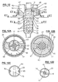
- Figures 10 and 11 show another embodiment of mixing rotor 60 which is a part of the mixer illustrated in Figure 12 .
- Components that are equivalent to the mixer according to Figure 1 are designated by the same reference numerals.
- the required feed pressure is further reduced by conveyor blades 17 provided on distributor body 63 in antechamber 32.
- end portion 68 of distributor body 63 has an oval shape such that a passage 69 in the form of two rotating gaps results between end portion 68 and the wall of rotor housing 25.
- Figure 12B shows the end of channel 53, leading to the edge of end portion 68 of distributor body 63 in antechamber 32 through inlet opening 54.
- End portion 68 of distributor body 63 is connected by two lateral ridges 65 to a disk portion 64 having a passage aperture 70 in the form of a slot. cf. Figures 10 and 12C .
- Passage aperture 70 extends from the edge of disk portion 64 through its center up to the area near the opposite edge thereof, cf. Figure 12C .
- disk portion 64 is connected to rotor hub 61 in such a way that a preponderantly central passage 71 from mixing chamber 36 to post-mixing chamber 37 results.
- Mixing blades 15 and 16 arranged in multiple planes on rotor hub 61, are designed for favorable flow characteristics in order to avoid the inclusion of air bubbles cf.
- Figures 1D and 12D are designed for favorable flow characteristics in order to avoid the inclusion of air bubbles cf.
- component A is pressed through inlet channel 50 into antechamber 32, guided around the axis of rotation and distributed over the entire cross-section by rotating distributor body 63, and delivered through the rotating passages 69 to mixing chamber 36 in the form of a thin, continuous layer.
- Component B is introduced into antechamber 32 radially and premixed with component A.
- the components are further mixed in combination with passage aperture 70 and central passage 71 and subsequently reach post-mixing chamber 37 where they are post-mixed and finally discharged.
- inlet opening 54 to antechamber 32 is arranged in the area of passage 19 or 69, respectively. It is conceivable to provide more than one inlet opening 54 in order to be able to introduce component B in multiple locations. It is further conceivable to arrange inlet opening 54 after passage 19 or 69, respectively, for example in such a manner that inlet channel 53 ends in mixing chamber 36.
- the optimized design of the mixing operation and the central arrangement of the different mixing elements allow a smaller pressure loss and a reduced mixer drive torque.
- the reduced friction in the medium reduces energy consumption, thereby resulting in a reduced temperature increase of the mixed material.
- the inlets and outlets are generally identical and the inlets are insertable into the outlets; but other variants are also possible where the outlets are insertable into the inlets.
- more than only one additional, smaller component may be admixed to the larger component.
- another inlet as well as another channel having an inlet opening near the passage are required.
- the depicted and disclosed characteristic features may be combined with each other as desired.
Landscapes
- Chemical & Material Sciences (AREA)
- Chemical Kinetics & Catalysis (AREA)
- Health & Medical Sciences (AREA)
- Mechanical Engineering (AREA)
- Engineering & Computer Science (AREA)
- Animal Behavior & Ethology (AREA)
- Oral & Maxillofacial Surgery (AREA)
- Public Health (AREA)
- Veterinary Medicine (AREA)
- Life Sciences & Earth Sciences (AREA)
- Epidemiology (AREA)
- Dentistry (AREA)
- General Health & Medical Sciences (AREA)
- Geometry (AREA)
- Physics & Mathematics (AREA)
- Dispersion Chemistry (AREA)
- Mixers Of The Rotary Stirring Type (AREA)
- Processing And Handling Of Plastics And Other Materials For Molding In General (AREA)
- Engine Equipment That Uses Special Cycles (AREA)
- Food-Manufacturing Devices (AREA)
- Accessories For Mixers (AREA)
Claims (11)
- Dynamischer Mischer, umfassend ein Rotorgehäuse (25), in welchem ein Mischrotor, der eine Rotornabe (11) umfasst, angeordnet ist, und das auf der Einlassseite durch einen Deckel (45) verschlossen ist, an welchem Einlässe für die Komponenten angeordnet sind, wobei die Einlässe (47, 48) für die Komponenten zu einer Vorkammer (32) führen, die mit einer folgenden Mischkammer (36, 37) über zumindest einen Durchgang (19, 69) in Verbindung steht, und der Mischrotor (10, 60) einen Verteilerkörper (13, 63) umfasst, der in der Vorkammer (32) angeordnet ist, um die Komponenten um die Drehachse des Mischrotors herum zu verteilen, dadurch gekennzeichnet, dass der Verteilerkörper (13, 63) einen Längsquerschnitt aufweist, der in Richtung der Rotornabe (11) gekrümmt ist, und der Mischrotor (10, 60) ferner einen Scheibenabschnitt (14, 64) umfasst, der zumindest eine Durchgangsdurchbrechung (20, 70) aufweist, wobei der Scheibenabschnitt, in der Strömungsrichtung der Komponenten gesehen, nach der Vorkammer (32) angeordnet ist, und der Mischrotor (10, 60) mit Mischschaufeln (15, 16) versehen ist, die in einer Nachmischkammer (37) nach dem Scheibenabschnitt (14) angeordnet sind.
- Dynamischer Mischer nach Anspruch 1 zum Mischen von Komponenten in unterschiedlichen Volumenmengen, dadurch gekennzeichnet, dass der Einlass (47) für die erste Komponente (A) mit der größeren Volumenmenge in dem oberen Bereich der Vorkammer (32) endet, der Einlass (48) für eine zweite Komponente (B) mit einer kleineren Volumenmenge in zumindest einer Einlassöffnung (54) endet, die in dem Bereich des Durchgangs (19, 69) zu der Mischkammer (36) angeordnet ist, und der Verteilerkörper (13, 63) zum Verteilen der zwei Komponenten um die Drehachse des Mischrotors herum angeordnet ist.
- Dynamischer Mischer nach Anspruch 1, zum Mischen von Komponenten in gleichen Volumenmengen, dadurch gekennzeichnet, dass die beiden Einlässe (47, 48) für die Komponenten in dem oberen Bereich der Vorkammer (32) enden, und der Verteilerkörper (13, 63) zum Verteilen der zwei Komponenten um die Drehachse des Mischrotors herum angeordnet ist.
- Mischer nach einem der vorhergehenden Ansprüche, wobei der Durchgang (19, 69) durch einen Spalt oder mehrere Spalten zwischen dem Umfang (18, 68) des Verteilerkörpers (13, 63) und der Wand (31, 51) des Rotorgehäuses (25) und/oder dem Rotorgehäusedeckel (45) gebildet ist.
- Mischer nach einem der vorhergehenden Ansprüche, wobei die Einlassöffnung (54) für die zweite Komponente derart angeordnet ist, dass letztere im Wesentlichen quer zur Drehachse des Mischrotors (10, 60) zugeführt wird.
- Mischer nach einem der vorhergehenden Ansprüche, wobei die Mischkammer (36) im Wesentlichen durch eine Wand des Rotorgehäuses (25), die Auslassseite (18, 68) des Verteilerkörpers (13, 63) und die Auslassseite des Scheibenabschnitts (14, 64) gebildet ist, und wobei die Durchgangsdurchbrechung/die Durchgangsdurchbrechungen (20, 70) derart konstruiert ist/ sind, dass die Komponenten, während sie durch die Mischkammer strömen, in Richtung der Drehachse abgelenkt werden.
- Mischer nach Anspruch 6, wobei das Rotorgehäuse (25) eine verengende Stufe (35) aufweist, die als eine Abstützung für den Scheibenabschnitt (14, 64) dient und die die Mischkammer gegenüber einer folgenden Nachmischkammer (37) an ihrem Umfang abdichtet.
- Mischer nach einem der vorhergehenden Ansprüche, wobei der Verteilerkörper (63) mit darauf angeordneten Förderschaufeln (17) versehen ist.
- Mischer nach Anspruch 8, wobei die Mischschaufeln (15, 16) einen im Wesentlichen rautenförmigen Querschnitt für günstige Strömungseigenschaften aufweisen, wobei zwei entgegengesetzte Mischschaufeln je Ebene oder alle Mischschaufeln ein tropfen- oder hakenförmiges Ende an ihren Seiten, die von der Drehrichtung abgewandt sind, aufweisen.
- Abgabebaugruppe, die eine Doppelkartusche oder eine Abgabevorrichtung und einen dynamischen Mischer nach einem der Ansprüche 1 bis 9 umfasst, wobei die Doppelkartusche oder die Abgabevorrichtung Auslässe und der Mischer Einlässe aufweisen, deren Durchmesser verschieden sind, wobei der größere Auslass über den größeren Einlass schiebbar ist und der kleinere Auslass in den kleineren Einlass einsetzbar ist.
- Abgabebaugruppe, die eine Doppelkartusche oder eine Abgabevorrichtung und einen dynamischen Mischer nach einem der Ansprüche 1 bis 9 umfasst, wobei der Rotorgehäusedeckel (45) des Mischers und die Kartusche (3) oder die Abgabevorrichtung Codiermittel (56) umfassen, um die Anbringung des Mischers in nur einer einzigen besonderen Ausrichtung zuzulassen.
Priority Applications (2)
| Application Number | Priority Date | Filing Date | Title |
|---|---|---|---|
| PL06790929T PL1943012T3 (pl) | 2005-10-07 | 2006-10-03 | Dynamiczna mieszarka |
| SI200630617T SI1943012T1 (sl) | 2005-10-07 | 2006-10-03 | Dinamični mešalnik |
Applications Claiming Priority (2)
| Application Number | Priority Date | Filing Date | Title |
|---|---|---|---|
| CH16192005 | 2005-10-07 | ||
| PCT/CH2006/000538 WO2007041878A1 (en) | 2005-10-07 | 2006-10-03 | Dynamic mixer |
Publications (2)
| Publication Number | Publication Date |
|---|---|
| EP1943012A1 EP1943012A1 (de) | 2008-07-16 |
| EP1943012B1 true EP1943012B1 (de) | 2010-01-13 |
Family
ID=35470866
Family Applications (1)
| Application Number | Title | Priority Date | Filing Date |
|---|---|---|---|
| EP06790929A Active EP1943012B1 (de) | 2005-10-07 | 2006-10-03 | Dynamischer mischer |
Country Status (17)
| Country | Link |
|---|---|
| US (1) | US8313232B2 (de) |
| EP (1) | EP1943012B1 (de) |
| JP (1) | JP4943441B2 (de) |
| KR (1) | KR101275062B1 (de) |
| CN (1) | CN101282781B (de) |
| AT (1) | ATE454933T1 (de) |
| AU (1) | AU2006301860B2 (de) |
| BR (1) | BRPI0616966B8 (de) |
| CA (1) | CA2624819C (de) |
| DE (1) | DE602006011772D1 (de) |
| DK (1) | DK1943012T3 (de) |
| ES (1) | ES2337833T3 (de) |
| IL (1) | IL190615A (de) |
| PL (1) | PL1943012T3 (de) |
| RU (1) | RU2414956C2 (de) |
| SI (1) | SI1943012T1 (de) |
| WO (1) | WO2007041878A1 (de) |
Cited By (5)
| Publication number | Priority date | Publication date | Assignee | Title |
|---|---|---|---|---|
| WO2012055926A1 (de) | 2010-10-26 | 2012-05-03 | Kettenbach Gmbh & Co. Kg | Doppelkartusche, mischer hierfür und kombination aus doppelkartusche und mischer |
| WO2013026716A1 (de) | 2011-08-24 | 2013-02-28 | Kettenbach Gmbh & Co. Kg | System aus kartuschen und mischern |
| WO2013026722A1 (de) | 2011-08-24 | 2013-02-28 | Kettenbach Gmbh & Co. Kg | Mischer |
| WO2019020768A1 (de) | 2017-07-28 | 2019-01-31 | Kettenbach Gmbh & Co. Kg | Mischer mit kompensationskanal und/oder staukammer |
| DE102017117199A1 (de) | 2017-07-28 | 2019-01-31 | 3lmed GmbH | Mischer mit Kompensationskanal und/oder Staukammer |
Families Citing this family (32)
| Publication number | Priority date | Publication date | Assignee | Title |
|---|---|---|---|---|
| DE202005005833U1 (de) * | 2005-02-25 | 2005-06-23 | Vosschemie Gmbh | Vorrichtung zum Vermischen einer Binder- und einer Härter-Komponente |
| DE102006038897B4 (de) * | 2006-08-18 | 2014-10-16 | Mühlbauer Technology Gmbh | Gerät zum Erzeugen einer Mehrkomponentenmasse |
| EP2102076B1 (de) | 2006-12-15 | 2011-10-26 | 3M Innovative Properties Company | Mischung und ausgabe härtbarer materialien aus mehreren bestandteilen |
| US20080267005A1 (en) * | 2007-04-24 | 2008-10-30 | Tyco Healthcare Group Lp | Applicator system and method of use |
| CH699611B1 (de) * | 2007-05-01 | 2010-04-15 | Sulzer Mixpac Ag | Tischgerät zum Mischen und Austragen von Mehrkomponentenmassen. |
| US8651731B2 (en) * | 2007-09-10 | 2014-02-18 | Sulzer Mixpac Ag | Dynamic mixer |
| DE102008008852A1 (de) * | 2008-02-13 | 2009-08-27 | Dibau Gmbh & Co. Kg | Ortsunabhängige, mobile Auspressvorrichtung zum parallelen Auspressen eines in zwei Folienbeutel verpackten 2-Komponenten Kleb- und Dichtstoffes mit einem Volumen-Mischungsverhältnis zwischen 7,6:1 und 8,3:1 |
| DE102008008964A1 (de) * | 2008-02-13 | 2009-08-27 | Dibau Gmbh & Co. Kg | Anflanschbare dynamische Mischvorrichtung für einen in Folienbeutel verpackten 2-Komponenten Kleb- und Dichtstoff mit einem Volumen-Mischungsverhältnis zwischen 7,6:1 und 8,3:1 |
| ES2338620B1 (es) * | 2008-04-25 | 2011-02-18 | Instalaciones Industriales Grau, S.L. | Dispositivo mezclador de fluidos por rotor de aspas fijas y moviles. |
| GB0915007D0 (en) † | 2009-08-28 | 2009-09-30 | 3M Innovative Properties Co | Mixer and system for mixing and dispensing material |
| EP2399666B1 (de) * | 2010-06-22 | 2013-02-20 | 3M Innovative Properties Company | Mischvorrichtung zum Herstellen eines Dentalmaterials, sowie System enthaltend einen solchen |
| EP2441413A1 (de) * | 2010-10-18 | 2012-04-18 | 3M Innovative Properties Company | Mischer zur Herstellung von Zahnmaterial, System mit dem Mischer und Verfahren zur Montage des Mischers |
| EP2468415A1 (de) * | 2010-12-24 | 2012-06-27 | Sika Technology AG | Dosier- und Mischvorrichtung für Mehrkomponentenstoffe |
| KR101913678B1 (ko) * | 2011-02-28 | 2018-10-31 | 술저 믹스팩 아게 | 동적 혼합기 및 그의 용도 |
| MX337340B (es) * | 2011-02-28 | 2016-02-26 | Sulzer Mixpac Ag | Mezcladora dinamica. |
| CN104645844A (zh) * | 2011-03-15 | 2015-05-27 | 中国纺织科学研究院 | 一种动态混合器 |
| CN102160971A (zh) * | 2011-03-15 | 2011-08-24 | 中国纺织科学研究院 | 一种动态混合器 |
| EP2520360B1 (de) * | 2011-05-02 | 2014-07-16 | Sulzer Mixpac AG | Mischer zum Mischen von mindestens zwei fliessfähigen Komponenten sowie Austragsvorrichtung |
| KR101091062B1 (ko) * | 2011-07-04 | 2011-12-08 | (주) 세일덴텍 | 자동형 치과인상재 혼합 믹싱팁 |
| IN2012DE01330A (de) | 2011-07-22 | 2015-09-25 | Sulzer Mixpac Ag | |
| CN102814131A (zh) * | 2012-07-10 | 2012-12-12 | 广饶彤鑫工贸有限公司 | 双螺旋混合器 |
| US8960501B2 (en) * | 2012-10-23 | 2015-02-24 | Nordson Corporation | Dispensing assembly and method for dispensing a mixed fluid |
| KR102023143B1 (ko) * | 2012-11-08 | 2019-09-19 | 술저 믹스팩 아게 | 2개 이상의 유동성 성분을 위한 카트리지 |
| KR101698170B1 (ko) | 2013-07-24 | 2017-01-19 | (주) 디유티코리아 | 가변 다단 회전임펠러를 갖는 터보 다이나믹 믹서 |
| KR101406068B1 (ko) * | 2013-09-05 | 2014-06-11 | (주)디엑스엠 | 디스펜서용 믹싱팁 |
| US9827539B2 (en) * | 2015-07-31 | 2017-11-28 | Phillip Phung-I Ho | Dynamic mixer head |
| CN105921089B (zh) * | 2016-04-27 | 2018-06-26 | 沈阳派司钛设备有限公司 | 一种氟化氢预反应器螺旋叶片 |
| US10792627B2 (en) * | 2018-05-08 | 2020-10-06 | Sensia Llc | Fluid mixing systems and methods |
| DE102019119160B4 (de) * | 2019-07-15 | 2025-12-18 | Kulzer Gmbh | Dynamischer Mischer mit balancierbaren Zuführkanälen und Verfahren zur Herstellung des Mischers |
| CN112076649A (zh) * | 2020-09-22 | 2020-12-15 | 安徽富邦药业有限公司 | 一种用于复方氨基酸注射液生产的配滤装置 |
| DE102020134316A1 (de) * | 2020-12-18 | 2022-06-23 | Kulzer Gmbh | Rotorwelle mit Schneckengewinde für einen dynamischen Mischer zum Mischen niedrig- bis hochviskoser Komponenten |
| US20250050288A1 (en) * | 2023-08-10 | 2025-02-13 | Phillip Phung-I Ho | Dynamic mixer head |
Family Cites Families (16)
| Publication number | Priority date | Publication date | Assignee | Title |
|---|---|---|---|---|
| DE4235736C1 (de) * | 1992-10-23 | 1994-03-24 | Bergmann Franz Josef | Vorrichtung zum Mischen und Austragen pastöser Massen |
| US5424054A (en) * | 1993-05-21 | 1995-06-13 | International Business Machines Corporation | Carbon fibers and method for their production |
| WO1995026925A1 (en) * | 1994-03-30 | 1995-10-12 | Massachusetts Institute Of Technology | Production of fullerenic nanostructures in flames |
| JPH09115334A (ja) * | 1995-10-23 | 1997-05-02 | Mitsubishi Materiais Corp | 透明導電膜および膜形成用組成物 |
| US6221330B1 (en) * | 1997-08-04 | 2001-04-24 | Hyperion Catalysis International Inc. | Process for producing single wall nanotubes using unsupported metal catalysts |
| DE59908763D1 (de) * | 1998-10-14 | 2004-04-08 | Kettenbach Gmbh & Co Kg A | Vorrichtung zum Öffnen zweier jeweils eine pastöse Masse beinhaltendender Schlauchbeutel |
| DE29907573U1 (de) | 1999-04-28 | 2000-09-07 | Ernst Mühlbauer KG, 22547 Hamburg | Dynamischer Mischer für zahnärztliche Abdruckmassen |
| ATE355891T1 (de) * | 1999-12-02 | 2007-03-15 | Mixpac Systems Ag | Dynamischer mischer |
| US6443612B1 (en) * | 1999-12-02 | 2002-09-03 | Wilhelm A. Keller | Dynamic mixer |
| DE59904983D1 (de) * | 1999-12-23 | 2003-05-15 | Muehlbauer Ernst Gmbh & Co Kg | Dynamischer Mischer für zahnärztliche Abdruckmassen |
| ATE384094T1 (de) * | 2000-03-28 | 2008-02-15 | Univ Oklahoma State | Anordnung selbsttragender filme mittels eines schichtweisen verfahrens |
| DE10043489A1 (de) * | 2000-09-01 | 2002-03-14 | Heraeus Kulzer Gmbh & Co Kg | Dynamischer Mischer II |
| KR20040030553A (ko) * | 2001-03-26 | 2004-04-09 | 에이코스 인코포레이티드 | 탄소 나노튜브를 함유하는 코팅막 |
| DE20302987U1 (de) * | 2003-02-24 | 2003-04-24 | Ernst Muehlbauer Gmbh & Co Kg | Dynamischer Mischer |
| JP2006519699A (ja) * | 2003-03-06 | 2006-08-31 | デンツプライ インターナショナル インコーポレーテッド | 分配及び混合用チップ |
| JP4413561B2 (ja) | 2003-09-01 | 2010-02-10 | 株式会社ジーシー | 歯科用印象材用撹拌ミキサー |
-
2006
- 2006-10-03 WO PCT/CH2006/000538 patent/WO2007041878A1/en not_active Ceased
- 2006-10-03 SI SI200630617T patent/SI1943012T1/sl unknown
- 2006-10-03 RU RU2008118148/05A patent/RU2414956C2/ru not_active IP Right Cessation
- 2006-10-03 JP JP2008533844A patent/JP4943441B2/ja not_active Expired - Fee Related
- 2006-10-03 US US12/083,145 patent/US8313232B2/en active Active
- 2006-10-03 CA CA2624819A patent/CA2624819C/en not_active Expired - Fee Related
- 2006-10-03 ES ES06790929T patent/ES2337833T3/es active Active
- 2006-10-03 DK DK06790929.1T patent/DK1943012T3/da active
- 2006-10-03 EP EP06790929A patent/EP1943012B1/de active Active
- 2006-10-03 DE DE602006011772T patent/DE602006011772D1/de active Active
- 2006-10-03 BR BRPI0616966A patent/BRPI0616966B8/pt active IP Right Grant
- 2006-10-03 CN CN2006800372224A patent/CN101282781B/zh active Active
- 2006-10-03 PL PL06790929T patent/PL1943012T3/pl unknown
- 2006-10-03 AU AU2006301860A patent/AU2006301860B2/en not_active Ceased
- 2006-10-03 AT AT06790929T patent/ATE454933T1/de active
-
2008
- 2008-04-03 IL IL190615A patent/IL190615A/en not_active IP Right Cessation
- 2008-04-17 KR KR1020087009220A patent/KR101275062B1/ko not_active Expired - Fee Related
Cited By (9)
| Publication number | Priority date | Publication date | Assignee | Title |
|---|---|---|---|---|
| WO2012055926A1 (de) | 2010-10-26 | 2012-05-03 | Kettenbach Gmbh & Co. Kg | Doppelkartusche, mischer hierfür und kombination aus doppelkartusche und mischer |
| WO2013026716A1 (de) | 2011-08-24 | 2013-02-28 | Kettenbach Gmbh & Co. Kg | System aus kartuschen und mischern |
| WO2013026722A1 (de) | 2011-08-24 | 2013-02-28 | Kettenbach Gmbh & Co. Kg | Mischer |
| US9272252B2 (en) | 2011-08-24 | 2016-03-01 | Kettenbach Gmbh & Co. Kg | System composed of cartridges and mixers |
| US9463079B2 (en) | 2011-08-24 | 2016-10-11 | Kettenbach Gmbh & Co. Kg | Mixer |
| WO2019020768A1 (de) | 2017-07-28 | 2019-01-31 | Kettenbach Gmbh & Co. Kg | Mischer mit kompensationskanal und/oder staukammer |
| DE102017117199A1 (de) | 2017-07-28 | 2019-01-31 | 3lmed GmbH | Mischer mit Kompensationskanal und/oder Staukammer |
| US11717794B2 (en) | 2017-07-28 | 2023-08-08 | 3lmed GmbH | Mixer |
| US11986785B2 (en) | 2017-07-28 | 2024-05-21 | 3lmed GmbH | Mixer having compensation channel and/or reservoir chamber |
Also Published As
| Publication number | Publication date |
|---|---|
| ATE454933T1 (de) | 2010-01-15 |
| DE602006011772D1 (de) | 2010-03-04 |
| PL1943012T3 (pl) | 2010-06-30 |
| SI1943012T1 (sl) | 2010-05-31 |
| CA2624819A1 (en) | 2007-04-19 |
| CN101282781A (zh) | 2008-10-08 |
| JP4943441B2 (ja) | 2012-05-30 |
| IL190615A (en) | 2011-06-30 |
| US20090296516A1 (en) | 2009-12-03 |
| JP2009509758A (ja) | 2009-03-12 |
| RU2414956C2 (ru) | 2011-03-27 |
| KR101275062B1 (ko) | 2013-06-14 |
| CA2624819C (en) | 2014-07-08 |
| BRPI0616966B1 (pt) | 2017-12-05 |
| EP1943012A1 (de) | 2008-07-16 |
| WO2007041878A1 (en) | 2007-04-19 |
| DK1943012T3 (da) | 2010-03-29 |
| ES2337833T3 (es) | 2010-04-29 |
| RU2008118148A (ru) | 2009-11-20 |
| AU2006301860B2 (en) | 2010-11-11 |
| IL190615A0 (en) | 2008-11-03 |
| BRPI0616966A2 (pt) | 2011-07-05 |
| BRPI0616966B8 (pt) | 2023-03-21 |
| KR20080046744A (ko) | 2008-05-27 |
| US8313232B2 (en) | 2012-11-20 |
| CN101282781B (zh) | 2010-06-23 |
| AU2006301860A1 (en) | 2007-04-19 |
Similar Documents
| Publication | Publication Date | Title |
|---|---|---|
| AU2006301860B2 (en) | Dynamic mixer | |
| US9656224B2 (en) | Dynamic mixer | |
| US6540395B2 (en) | Dynamic mixer for dental impression compounds | |
| US6932243B2 (en) | Dispensing assembly with dynamic mixer | |
| CN103534016B (zh) | 动态混合器及其用途 | |
| US20090207685A1 (en) | Mixer | |
| JP2011521670A (ja) | ダイナミックミキサー | |
| JP2003516840A (ja) | 動的混合機 | |
| RU2521648C1 (ru) | Миксер для приготовления стоматологического материала и система, его содержащая | |
| KR20070058633A (ko) | 복수의 구성요소 페이스트용 믹서, 키트와 페이스트구성요소를 혼합하는 방법 | |
| EP1892033B1 (de) | Vorrichtung und Verfahren zum Mischen einer Mehrkomponentenmasse für dentale Gusswerkstücke | |
| US20080264809A1 (en) | Method for the Production of Dental Moulding Materials and Device Therefor | |
| MX2008004420A (en) | Dynamic mixer | |
| JP3727183B2 (ja) | ペースト練和装置 | |
| JP3793671B2 (ja) | ペースト練和装置 |
Legal Events
| Date | Code | Title | Description |
|---|---|---|---|
| PUAI | Public reference made under article 153(3) epc to a published international application that has entered the european phase |
Free format text: ORIGINAL CODE: 0009012 |
|
| 17P | Request for examination filed |
Effective date: 20080507 |
|
| AK | Designated contracting states |
Kind code of ref document: A1 Designated state(s): AT BE BG CH CY CZ DE DK EE ES FI FR GB GR HU IE IS IT LI LT LU LV MC NL PL PT RO SE SI SK TR |
|
| 17Q | First examination report despatched |
Effective date: 20080805 |
|
| GRAP | Despatch of communication of intention to grant a patent |
Free format text: ORIGINAL CODE: EPIDOSNIGR1 |
|
| RAP1 | Party data changed (applicant data changed or rights of an application transferred) |
Owner name: SULZER MIXPAC AG |
|
| GRAS | Grant fee paid |
Free format text: ORIGINAL CODE: EPIDOSNIGR3 |
|
| GRAA | (expected) grant |
Free format text: ORIGINAL CODE: 0009210 |
|
| AK | Designated contracting states |
Kind code of ref document: B1 Designated state(s): AT BE BG CH CY CZ DE DK EE ES FI FR GB GR HU IE IS IT LI LT LU LV MC NL PL PT RO SE SI SK TR |
|
| REG | Reference to a national code |
Ref country code: GB Ref legal event code: FG4D |
|
| REG | Reference to a national code |
Ref country code: CH Ref legal event code: NV Representative=s name: SULZER MANAGEMENT AG PATENTABTEILUNG/0067 Ref country code: CH Ref legal event code: EP |
|
| REG | Reference to a national code |
Ref country code: IE Ref legal event code: FG4D |
|
| REF | Corresponds to: |
Ref document number: 602006011772 Country of ref document: DE Date of ref document: 20100304 Kind code of ref document: P |
|
| REG | Reference to a national code |
Ref country code: DK Ref legal event code: T3 |
|
| REG | Reference to a national code |
Ref country code: SE Ref legal event code: TRGR |
|
| REG | Reference to a national code |
Ref country code: NL Ref legal event code: T3 |
|
| REG | Reference to a national code |
Ref country code: ES Ref legal event code: FG2A Ref document number: 2337833 Country of ref document: ES Kind code of ref document: T3 |
|
| LTIE | Lt: invalidation of european patent or patent extension |
Effective date: 20100113 |
|
| PG25 | Lapsed in a contracting state [announced via postgrant information from national office to epo] |
Ref country code: LT Free format text: LAPSE BECAUSE OF FAILURE TO SUBMIT A TRANSLATION OF THE DESCRIPTION OR TO PAY THE FEE WITHIN THE PRESCRIBED TIME-LIMIT Effective date: 20100113 Ref country code: PT Free format text: LAPSE BECAUSE OF FAILURE TO SUBMIT A TRANSLATION OF THE DESCRIPTION OR TO PAY THE FEE WITHIN THE PRESCRIBED TIME-LIMIT Effective date: 20100513 Ref country code: IS Free format text: LAPSE BECAUSE OF FAILURE TO SUBMIT A TRANSLATION OF THE DESCRIPTION OR TO PAY THE FEE WITHIN THE PRESCRIBED TIME-LIMIT Effective date: 20100513 |
|
| PG25 | Lapsed in a contracting state [announced via postgrant information from national office to epo] |
Ref country code: LV Free format text: LAPSE BECAUSE OF FAILURE TO SUBMIT A TRANSLATION OF THE DESCRIPTION OR TO PAY THE FEE WITHIN THE PRESCRIBED TIME-LIMIT Effective date: 20100113 Ref country code: FI Free format text: LAPSE BECAUSE OF FAILURE TO SUBMIT A TRANSLATION OF THE DESCRIPTION OR TO PAY THE FEE WITHIN THE PRESCRIBED TIME-LIMIT Effective date: 20100113 |
|
| PG25 | Lapsed in a contracting state [announced via postgrant information from national office to epo] |
Ref country code: EE Free format text: LAPSE BECAUSE OF FAILURE TO SUBMIT A TRANSLATION OF THE DESCRIPTION OR TO PAY THE FEE WITHIN THE PRESCRIBED TIME-LIMIT Effective date: 20100113 Ref country code: GR Free format text: LAPSE BECAUSE OF FAILURE TO SUBMIT A TRANSLATION OF THE DESCRIPTION OR TO PAY THE FEE WITHIN THE PRESCRIBED TIME-LIMIT Effective date: 20100414 Ref country code: CY Free format text: LAPSE BECAUSE OF FAILURE TO SUBMIT A TRANSLATION OF THE DESCRIPTION OR TO PAY THE FEE WITHIN THE PRESCRIBED TIME-LIMIT Effective date: 20100113 Ref country code: RO Free format text: LAPSE BECAUSE OF FAILURE TO SUBMIT A TRANSLATION OF THE DESCRIPTION OR TO PAY THE FEE WITHIN THE PRESCRIBED TIME-LIMIT Effective date: 20100113 Ref country code: BE Free format text: LAPSE BECAUSE OF FAILURE TO SUBMIT A TRANSLATION OF THE DESCRIPTION OR TO PAY THE FEE WITHIN THE PRESCRIBED TIME-LIMIT Effective date: 20100113 |
|
| PLBE | No opposition filed within time limit |
Free format text: ORIGINAL CODE: 0009261 |
|
| STAA | Information on the status of an ep patent application or granted ep patent |
Free format text: STATUS: NO OPPOSITION FILED WITHIN TIME LIMIT |
|
| PG25 | Lapsed in a contracting state [announced via postgrant information from national office to epo] |
Ref country code: BG Free format text: LAPSE BECAUSE OF FAILURE TO SUBMIT A TRANSLATION OF THE DESCRIPTION OR TO PAY THE FEE WITHIN THE PRESCRIBED TIME-LIMIT Effective date: 20100413 Ref country code: SK Free format text: LAPSE BECAUSE OF FAILURE TO SUBMIT A TRANSLATION OF THE DESCRIPTION OR TO PAY THE FEE WITHIN THE PRESCRIBED TIME-LIMIT Effective date: 20100113 |
|
| 26N | No opposition filed |
Effective date: 20101014 |
|
| PG25 | Lapsed in a contracting state [announced via postgrant information from national office to epo] |
Ref country code: MC Free format text: LAPSE BECAUSE OF NON-PAYMENT OF DUE FEES Effective date: 20101031 |
|
| PG25 | Lapsed in a contracting state [announced via postgrant information from national office to epo] |
Ref country code: IE Free format text: LAPSE BECAUSE OF NON-PAYMENT OF DUE FEES Effective date: 20101003 |
|
| PG25 | Lapsed in a contracting state [announced via postgrant information from national office to epo] |
Ref country code: HU Free format text: LAPSE BECAUSE OF FAILURE TO SUBMIT A TRANSLATION OF THE DESCRIPTION OR TO PAY THE FEE WITHIN THE PRESCRIBED TIME-LIMIT Effective date: 20100714 Ref country code: LU Free format text: LAPSE BECAUSE OF NON-PAYMENT OF DUE FEES Effective date: 20101003 |
|
| PGFP | Annual fee paid to national office [announced via postgrant information from national office to epo] |
Ref country code: TR Payment date: 20121001 Year of fee payment: 7 |
|
| REG | Reference to a national code |
Ref country code: CH Ref legal event code: NV Representative=s name: DR. GRAF AND PARTNER AG INTELLECTUAL PROPERTY, CH |
|
| PG25 | Lapsed in a contracting state [announced via postgrant information from national office to epo] |
Ref country code: TR Free format text: LAPSE BECAUSE OF NON-PAYMENT OF DUE FEES Effective date: 20131003 |
|
| REG | Reference to a national code |
Ref country code: FR Ref legal event code: PLFP Year of fee payment: 10 |
|
| PGFP | Annual fee paid to national office [announced via postgrant information from national office to epo] |
Ref country code: PL Payment date: 20150922 Year of fee payment: 10 |
|
| PGFP | Annual fee paid to national office [announced via postgrant information from national office to epo] |
Ref country code: DK Payment date: 20151021 Year of fee payment: 10 |
|
| PGFP | Annual fee paid to national office [announced via postgrant information from national office to epo] |
Ref country code: SE Payment date: 20151021 Year of fee payment: 10 Ref country code: SI Payment date: 20150923 Year of fee payment: 10 Ref country code: CZ Payment date: 20151001 Year of fee payment: 10 Ref country code: AT Payment date: 20151022 Year of fee payment: 10 Ref country code: NL Payment date: 20151021 Year of fee payment: 10 |
|
| REG | Reference to a national code |
Ref country code: FR Ref legal event code: PLFP Year of fee payment: 11 |
|
| REG | Reference to a national code |
Ref country code: DK Ref legal event code: EBP Effective date: 20161031 |
|
| PG25 | Lapsed in a contracting state [announced via postgrant information from national office to epo] |
Ref country code: CZ Free format text: LAPSE BECAUSE OF NON-PAYMENT OF DUE FEES Effective date: 20161003 |
|
| REG | Reference to a national code |
Ref country code: NL Ref legal event code: MM Effective date: 20161101 |
|
| REG | Reference to a national code |
Ref country code: AT Ref legal event code: MM01 Ref document number: 454933 Country of ref document: AT Kind code of ref document: T Effective date: 20161003 |
|
| REG | Reference to a national code |
Ref country code: SI Ref legal event code: KO00 Effective date: 20170609 |
|
| PG25 | Lapsed in a contracting state [announced via postgrant information from national office to epo] |
Ref country code: SE Free format text: LAPSE BECAUSE OF NON-PAYMENT OF DUE FEES Effective date: 20161004 Ref country code: AT Free format text: LAPSE BECAUSE OF NON-PAYMENT OF DUE FEES Effective date: 20161003 Ref country code: NL Free format text: LAPSE BECAUSE OF NON-PAYMENT OF DUE FEES Effective date: 20161101 Ref country code: SI Free format text: LAPSE BECAUSE OF NON-PAYMENT OF DUE FEES Effective date: 20161004 |
|
| REG | Reference to a national code |
Ref country code: FR Ref legal event code: PLFP Year of fee payment: 12 |
|
| PG25 | Lapsed in a contracting state [announced via postgrant information from national office to epo] |
Ref country code: DK Free format text: LAPSE BECAUSE OF NON-PAYMENT OF DUE FEES Effective date: 20161031 |
|
| PGFP | Annual fee paid to national office [announced via postgrant information from national office to epo] |
Ref country code: GB Payment date: 20171101 Year of fee payment: 15 |
|
| PG25 | Lapsed in a contracting state [announced via postgrant information from national office to epo] |
Ref country code: PL Free format text: LAPSE BECAUSE OF NON-PAYMENT OF DUE FEES Effective date: 20161003 |
|
| REG | Reference to a national code |
Ref country code: FR Ref legal event code: PLFP Year of fee payment: 13 |
|
| REG | Reference to a national code |
Ref country code: CH Ref legal event code: PL |
|
| PG25 | Lapsed in a contracting state [announced via postgrant information from national office to epo] |
Ref country code: CH Free format text: LAPSE BECAUSE OF NON-PAYMENT OF DUE FEES Effective date: 20181031 Ref country code: LI Free format text: LAPSE BECAUSE OF NON-PAYMENT OF DUE FEES Effective date: 20181031 |
|
| PGFP | Annual fee paid to national office [announced via postgrant information from national office to epo] |
Ref country code: ES Payment date: 20191122 Year of fee payment: 14 Ref country code: IT Payment date: 20191028 Year of fee payment: 14 |
|
| GBPC | Gb: european patent ceased through non-payment of renewal fee |
Effective date: 20201003 |
|
| PG25 | Lapsed in a contracting state [announced via postgrant information from national office to epo] |
Ref country code: GB Free format text: LAPSE BECAUSE OF NON-PAYMENT OF DUE FEES Effective date: 20201003 |
|
| PG25 | Lapsed in a contracting state [announced via postgrant information from national office to epo] |
Ref country code: IT Free format text: LAPSE BECAUSE OF NON-PAYMENT OF DUE FEES Effective date: 20201003 |
|
| REG | Reference to a national code |
Ref country code: DE Ref legal event code: R079 Ref document number: 602006011772 Country of ref document: DE Free format text: PREVIOUS MAIN CLASS: B01F0013000000 Ipc: B01F0033000000 |
|
| REG | Reference to a national code |
Ref country code: ES Ref legal event code: FD2A Effective date: 20220119 |
|
| PG25 | Lapsed in a contracting state [announced via postgrant information from national office to epo] |
Ref country code: ES Free format text: LAPSE BECAUSE OF NON-PAYMENT OF DUE FEES Effective date: 20201004 |
|
| REG | Reference to a national code |
Ref country code: DE Ref legal event code: R081 Ref document number: 602006011772 Country of ref document: DE Owner name: MEDMIX SWITZERLAND AG, CH Free format text: FORMER OWNER: SULZER MIXPAC AG, HAAG, CH |
|
| PGFP | Annual fee paid to national office [announced via postgrant information from national office to epo] |
Ref country code: FR Payment date: 20221028 Year of fee payment: 17 |
|
| PG25 | Lapsed in a contracting state [announced via postgrant information from national office to epo] |
Ref country code: FR Free format text: LAPSE BECAUSE OF NON-PAYMENT OF DUE FEES Effective date: 20231031 |
|
| P01 | Opt-out of the competence of the unified patent court (upc) registered |
Free format text: CASE NUMBER: UPC_APP_412230/2023 Effective date: 20230505 |
|
| PGFP | Annual fee paid to national office [announced via postgrant information from national office to epo] |
Ref country code: DE Payment date: 20251021 Year of fee payment: 20 |