EP1943078B2 - Dispositif d'actionnement de pointeaux de vannes dans des dispositifs de moulage par injection comportant des buses a vannes a pointeaux - Google Patents
Dispositif d'actionnement de pointeaux de vannes dans des dispositifs de moulage par injection comportant des buses a vannes a pointeaux Download PDFInfo
- Publication number
- EP1943078B2 EP1943078B2 EP06829241.6A EP06829241A EP1943078B2 EP 1943078 B2 EP1943078 B2 EP 1943078B2 EP 06829241 A EP06829241 A EP 06829241A EP 1943078 B2 EP1943078 B2 EP 1943078B2
- Authority
- EP
- European Patent Office
- Prior art keywords
- actuating device
- self
- control rails
- rails
- needles
- Prior art date
- Legal status (The legal status is an assumption and is not a legal conclusion. Google has not performed a legal analysis and makes no representation as to the accuracy of the status listed.)
- Active
Links
Images

Classifications
-
- B—PERFORMING OPERATIONS; TRANSPORTING
- B29—WORKING OF PLASTICS; WORKING OF SUBSTANCES IN A PLASTIC STATE IN GENERAL
- B29C—SHAPING OR JOINING OF PLASTICS; SHAPING OF MATERIAL IN A PLASTIC STATE, NOT OTHERWISE PROVIDED FOR; AFTER-TREATMENT OF THE SHAPED PRODUCTS, e.g. REPAIRING
- B29C45/00—Injection moulding, i.e. forcing the required volume of moulding material through a nozzle into a closed mould; Apparatus therefor
- B29C45/17—Component parts, details or accessories; Auxiliary operations
- B29C45/26—Moulds
- B29C45/27—Sprue channels ; Runner channels or runner nozzles
- B29C45/28—Closure devices therefor
-
- B—PERFORMING OPERATIONS; TRANSPORTING
- B29—WORKING OF PLASTICS; WORKING OF SUBSTANCES IN A PLASTIC STATE IN GENERAL
- B29C—SHAPING OR JOINING OF PLASTICS; SHAPING OF MATERIAL IN A PLASTIC STATE, NOT OTHERWISE PROVIDED FOR; AFTER-TREATMENT OF THE SHAPED PRODUCTS, e.g. REPAIRING
- B29C45/00—Injection moulding, i.e. forcing the required volume of moulding material through a nozzle into a closed mould; Apparatus therefor
- B29C45/17—Component parts, details or accessories; Auxiliary operations
- B29C45/26—Moulds
- B29C45/27—Sprue channels ; Runner channels or runner nozzles
- B29C45/28—Closure devices therefor
- B29C45/2806—Closure devices therefor consisting of needle valve systems
- B29C45/281—Drive means therefor
-
- B—PERFORMING OPERATIONS; TRANSPORTING
- B29—WORKING OF PLASTICS; WORKING OF SUBSTANCES IN A PLASTIC STATE IN GENERAL
- B29C—SHAPING OR JOINING OF PLASTICS; SHAPING OF MATERIAL IN A PLASTIC STATE, NOT OTHERWISE PROVIDED FOR; AFTER-TREATMENT OF THE SHAPED PRODUCTS, e.g. REPAIRING
- B29C45/00—Injection moulding, i.e. forcing the required volume of moulding material through a nozzle into a closed mould; Apparatus therefor
- B29C45/17—Component parts, details or accessories; Auxiliary operations
- B29C45/26—Moulds
- B29C45/27—Sprue channels ; Runner channels or runner nozzles
- B29C45/28—Closure devices therefor
- B29C45/2806—Closure devices therefor consisting of needle valve systems
- B29C45/281—Drive means therefor
- B29C2045/2813—Common drive means for several needle valves
-
- B—PERFORMING OPERATIONS; TRANSPORTING
- B29—WORKING OF PLASTICS; WORKING OF SUBSTANCES IN A PLASTIC STATE IN GENERAL
- B29C—SHAPING OR JOINING OF PLASTICS; SHAPING OF MATERIAL IN A PLASTIC STATE, NOT OTHERWISE PROVIDED FOR; AFTER-TREATMENT OF THE SHAPED PRODUCTS, e.g. REPAIRING
- B29C45/00—Injection moulding, i.e. forcing the required volume of moulding material through a nozzle into a closed mould; Apparatus therefor
- B29C45/17—Component parts, details or accessories; Auxiliary operations
- B29C45/26—Moulds
- B29C45/27—Sprue channels ; Runner channels or runner nozzles
- B29C45/28—Closure devices therefor
- B29C45/2806—Closure devices therefor consisting of needle valve systems
- B29C45/281—Drive means therefor
- B29C2045/2831—Needle valves driven by a cam
-
- B—PERFORMING OPERATIONS; TRANSPORTING
- B29—WORKING OF PLASTICS; WORKING OF SUBSTANCES IN A PLASTIC STATE IN GENERAL
- B29C—SHAPING OR JOINING OF PLASTICS; SHAPING OF MATERIAL IN A PLASTIC STATE, NOT OTHERWISE PROVIDED FOR; AFTER-TREATMENT OF THE SHAPED PRODUCTS, e.g. REPAIRING
- B29C45/00—Injection moulding, i.e. forcing the required volume of moulding material through a nozzle into a closed mould; Apparatus therefor
- B29C45/17—Component parts, details or accessories; Auxiliary operations
- B29C45/83—Lubricating means
Definitions
- the invention relates to an actuating device for shut-off needles in injection molds with needle shut-off nozzles according to the preamble of claim 1 and an injection mold according to claim 27.
- Needle shut-off nozzles are used in injection molding tools in order to supply a flowable mass at a predeterminable temperature under high pressure to a separable mold insert. They usually have pneumatically or hydraulically driven shut-off needles that periodically open and close sprue openings in the mold insert.
- each shut-off needle is mounted so as to be axially displaceable in the tool-side area of the injection molding device and, in the nozzle-side area, is preferably passed centrally through a flow channel for the mass to be processed.
- the flow channel ends in a nozzle end piece that forms a nozzle outlet opening. In the closed position, the lower end of the shut-off needle engages in a sealing seat which is formed in the nozzle end piece or in the mold insert.
- shut-off needles For numerous applications, it is necessary to move all shut-off needles synchronously and to apply the same closing force, especially when several mold inserts are molded on at the same time in one tool.
- EP-A1-0 790 116 proposes to fix the shut-off needles of a nozzle group on a common carrier plate, which executes a lifting movement in the longitudinal direction of the shut-off needles.
- the carrier plate is for this purpose between two stationary Stops and arranged laterally between two guide rails, which are mounted for longitudinal displacement within a clamping plate and have obliquely arranged sliding blocks or sliding cams on their side surfaces facing the carrier plate. The latter engage laterally in the carrier plate, which is provided with oblique grooves. If the guide rails are pushed back and forth in the longitudinal direction by means of a drive, the carrier plate moves up and down perpendicularly to them. As a result, all the shut-off needles attached to the carrier plate perform the same lifting movement.
- the disadvantage here is that the oblique grooves of the carrier plate and the sliding blocks or cams guided therein are exposed to a relatively high degree of wear, especially in the case of rapid firing sequences. Despite the use of lubricants, this forces frequent maintenance interruptions. The operating and maintenance costs are correspondingly high.
- EP 1 184 152 A1 provides for the shut-off needles of a nozzle group to be fixed on a common carrier plate.
- the problem is the wear of the parts that move in relation to one another, which is why it is planned to coat them with sintered bronze, for example.
- Another way of coating mutually moving parts is, for example, as shown in U.S. 6,461,143 B1 shown, the application of diamond-like materials.
- each shut-off needle is attached to a separate needle carrier element.
- the latter are provided on two opposite flat sides with sloping guide cams which engage in sloping grooves of a fork-shaped sliding frame.
- a cylindrical section is formed on each needle carrier element, which is mounted in a guide bushing in the manner of a reciprocating piston in an axially displaceable manner. If you move the sliding frame back and forth, the individual needle carrier elements are moved up and down perpendicular to it.
- each shut-off needle is fastened to its needle carrier element by means of an elastic intermediate element, which reduces the assembly effort as well as increased manufacturing costs. High frictional forces between the guide cams and the sliding frame are also disadvantageous here.
- DE-A1-199 07 116 discloses an actuation mechanism for die cast valve elements formed between two tooling plates.
- the individual valve pins of a nozzle group are fixed to a common valve pin plate, which is provided with guide bushings on the edge and can slide up and down on guide bolts running parallel to the valve pins.
- Two actuating rods are fastened to the valve pin plate, which carry several sliding blocks on the sides. The latter engage in inclined grooves of two cam elements, which are mounted for longitudinal displacement between the upper tool plate and a holding plate each.
- JPH 0 542 568 A discloses a nozzle tip for an injection molding tool with a metal ring which is mounted in a longitudinally displaceable manner on the nozzle tip and is intended to prevent the material to be processed from flowing back.
- the metal ring is coated with diamond or a diamond-like material.
- U.S. 6,461,143 B1 describes a multi-part injection mold for the production of plate-shaped plastic objects.
- a longitudinally displaceable part of the injection molding tool is needle-shaped and is mounted in a channel of the tool so that it can be displaced longitudinally with ribs pointing radially outwards.
- the faces of the ribs and channel are coated with titanium nitride or a diamond-like material.
- the VDI Guideline 2840 summarizes the basics, layer types and properties of carbon layers that are deposited using vacuum coating technology (PVD or CVD).
- VDI guideline 3825 discloses surfaces/coatings of PVD or CVD coated tools and components, in particular hard material coatings.
- EP 1 025 974 A2 discloses an actuating device with a lifting plate for valve needles, on the back of which actuating bars are applied.
- the latter are each opposite a control rail, which is mounted in the tool so that it can be moved longitudinally by means of roller bearings.
- Sliding elements are attached to the actuating bars and slide in oblique grooves formed in the control rails.
- a needle valve system with the designation HPS III-NV from EWIKON Heisskanalsysteme GmbH & Co. KG.
- This system has a lifting plate on which at least two shut-off needles of two needle shut-off nozzles can be fixed, the lifting plate being movable between two control rails mounted to be longitudinally displaceable in a first direction in a second direction running transversely to the first direction.
- At least two sliding elements convert a movement of the control rails along the first direction into a lifting movement of the lifting plate in the second direction, the lifting plate being arranged alongside between the control rails and the sliding elements between the lifting plate and the control rails in the first direction and the second direction oblique grooves are arranged.
- Components that move relative to one another and are therefore at risk of wear, in particular the control rails and/or the sliding elements, are at least partially made of a self-lubricating material.
- the aim of the invention is to create a compact actuating device for injection molds with needle shut-off nozzles, which enables maintenance-free and permanently reliable actuation of all valve needles that are to be individually adjustable within the device.
- the actuating device should also be constructed inexpensively using simple means and be easy to handle.
- the invention provides that the control rails and/or the sliding elements, as components that move relative to one another and are therefore subject to wear, are at least partially made of a diamond-like material or at least partially coated with a self-lubricating or a diamond-like material.
- the adjective "diamond-like" here refers to materials with a very high
- valve needles By fixing the valve needles on a common lifting plate, it is ensured that all valve needles are always moved synchronously and are subjected to the same closing force.
- the sliding elements made of diamond-like material which are guided in the oblique grooves of the control rails and are subjected to lateral forces, ensure that all valve needles are actuated reliably over the long term, because the frictional forces within the grooves are reduced to a minimum.
- the sliding elements are at least partially, in particular in sections, coated with a self-lubricating material, or alternatively if they are at least partially coated with a diamond-like material. To prevent the sliding elements from twisting or tilting, they are embedded in the side of the lifting element.
- the invention further provides that the length of the sliding elements is greater than the thickness of the lifting element. This is therefore always guided precisely, with no point loads occurring within the inclined grooves.
- the lifting element is forcibly guided in the second direction, it being preferably arranged between two stops. These are at least partially coated with a self-lubricating material, so that the frictional forces between the lifting element and the stops are significantly reduced.
- the stops can also be made at least partially from a diamond-like material or coated with such a material.
- valve needles are designed to be adjustable along the second direction relative to the lifting element.
- valve needles can be fixed axially fixed and radially floating on the lifting plate according to a further aspect of the invention.
- the lifting element has at least one recess for the passage of a flow channel, a distributor arm or the like.
- control rails are connected to a drive, in particular via a common pushing element which forms a U-shaped frame together with the control rails.
- the control rails and the thrust element are connected to one another in a non-positive and/or positive manner. However, they can also be in one piece if required.
- control rails In order to achieve precise guidance of the control rails, they are slidably guided between guide elements. These are designed, for example, as guide rails that are attached to or in a clamping plate.
- the control rails have sliding strips on their side surfaces facing the guide rails, which slide strips are guided in grooves in the guide rails.
- the sliding strips are at least partially coated with a self-lubricating material.
- the components that move relative to one another can also be made at least partially from a diamond-like material or coated with such a material in order to reduce the wear caused by the relative movement.
- the guide elements are guide plates. These are attached to the tool and the control rails and are provided with sliding elements in the area of the sliding surfaces.
- the guide plates and/or the sliding elements are at least partially coated with a self-lubricating material, which has a favorable effect on the sliding properties.
- the self-lubricating material is a bearing metal, such as an alloy of lead, tin, aluminum or copper, or a sintered metal. Bronze or sintered bronze is preferably used.
- the surfaces of the diamond-like material are advantageously polished, resulting in a mirror-like surface with low surface roughness and a low coefficient of friction. Accordingly, the wear caused by the relative movement of the respective components can be further reduced.
- the components that wear out due to a relative movement are preferably arranged to be exchangeable, so that they can be replaced by new components at any time when they are worn.
- a special embodiment of the invention provides that the actuating device is formed in an injection mold, in particular in or on a clamping plate.
- the latter is provided with a depression for receiving the actuating device, which simplifies assembly.
- At least two actuating devices can be arranged in parallel next to one another, with both having a common drive.
- Actuating device for actuating a plurality of shut-off needles 16 in an injection molding device (not shown).
- the latter is used to produce molded parts from a flowable mass, for example a plastic melt.
- several needle shut-off nozzles are arranged under a distributor plate (not shown). These feed the plastic melt to be processed into a separable mold insert (likewise not shown), the sprue openings of which are periodically opened and closed by the shut-off needles 16 .
- a clamping plate 12 sits above the distributor plate and is provided with a rectangular indentation or recess 13 for receiving the actuating device 10 .
- Hoses or pipelines for a flow medium, which flows through the clamping plate 12 in bores 17 can be connected via connections 11 .
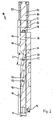
- a lifting element 20 is provided, on which in the embodiment of FIG 1 two shut-off needles 16 are attached.
- the lifting element 20 is preferably designed as a rectangular plate which lies parallel to the clamping plate 12 and is arranged alongside between two displaceably mounted control rails 30 . At the front, the plate 20 sits between two stationary stops 60, 62, which are fixed in the recess 13 of the clamping plate 12 by means of screws 63.
- Two dowel pins 66 each ensure precise alignment of the stops 60, 62, which are preferably rectangular in cross section, with the pins 66 being firmly fixed in the base 14 of the clamping plate 12 and being received with an exact fit by bores (not specified) in the stops 60, 62.
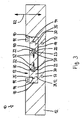
- the lifting plate 20 carries two sliding elements 50 on each side, which are slide-guided in parallel in the control rails 30 ( 2 and 3 ).
- the latter are provided on their side faces 32 facing the lifting plate 20 with two grooves 40 running obliquely to the clamping plate 12 and accommodating the sliding elements 50 except for a small amount of play.
- the control rails 30 are arranged within the recess 13 between two stationary guide rails 90 in a first direction R1 parallel to the platen 12 and are longitudinally displaceable and via a common pusher element 82 and a Adapter piece 86 connected to a drive 80.
- This is fastened to the outside of the clamping plate 12 by means of screws 81 , for example, with the adapter piece 86 being passed through a lateral (unspecified) bore or recess in the clamping plate 12 .
- the drive 80 can be an electric, pneumatic or hydraulic actuator or motor, which is preferably actuated by control electronics (likewise not shown).
- the pushing element 82 has two stepped ends 83 which are in engagement with the control rails 30 in such a way that in the first direction R1 there is always a tensile connection which, however, can be released perpendicular thereto.
- the control rails 30 have hook-shaped ends 33 which engage around the stepped ends 83 of the pushing element 82 in a form-fitting manner.
- the elements 30, 82 can be plugged into one another without tools when assembling the actuating device 10, which simplifies handling and has a favorable effect on the assembly costs.
- the components 30, 82 can be quickly replaced at any time, for example if a longer and/or wider lifting plate 20 is used. In the installed state, however, the sliding element 82 and the control rails 30 are always firmly coupled to one another in the direction of actuation R1.
- connection between the thrust element 82 and the adapter piece 86 is formed by a sliding block 88 with a T-shaped cross section, which is connected to the adapter piece 86 by means of a dowel pin 87 and which—also without a tool—is inserted into the thrust element 82 with a positive fit.
- the latter is provided with a recess 89 of the same shape for this purpose.
- the guide rails 90 lie laterally in the recess 13 of the adapter plate 12. They are fastened to the bottom 14 of the recess 13 by means of screws 91 and are each provided with a continuous guide groove 94 running parallel to the adapter plate 12 on their side surfaces 92 facing the control rails 30. Each guide groove 94 accommodates, with little play, a sliding strip 35 which is formed on a side face 39 of the control rail 30 facing the guide rails 90 .
- Alignment pins 96 ensure precise alignment of the guide rails 90 within the recess 13. They are firmly inserted in the base 14 of the clamping plate 12 and are received in the guide rails 90 with an exact fit by bores (unspecified).
- control rails 30 and the pusher element 82 form a U-shaped frame which laterally encloses the lifting plate 20 and the stops 60, 62 with little play of movement and which is slidably guided on the outside between the guide rails 90. If the drive 80 periodically moves the frame 30, 82 back and forth in the first direction R1, the lifting plate 20, which is forcibly guided between the stops 60, 62, is moved in a second direction R2 perpendicular to the moves up and down towards R1. The lifting plate 20 therefore performs a lifting movement together with the shut-off needles 16 fixed thereto, with all the shut-off needles 16 always being actuated at the same time and with the same closing force.
- the movement of the pushing element 82 in the first direction R1 is limited by stops.
- An end wall 15 of the recess 13 forms a first stop, while the stop 60 facing the drive 80 forms a second stop.
- the distance a between the end wall 15 and the stop 60 specifies the adjustment path for the pusher element 82 and thus for the control rails 30, which can therefore be moved back and forth between at least two defined positions.
- the lifting plate 20 performs a correspondingly defined lifting movement, whereby the drive 80 can also be used to move to intermediate positions in a targeted manner, for example if the shut-off needles 16 are to be brought into different closed and open positions.
- the plug connections between the components 30, 82 and 82, 86/89 have the advantage that the e.g. Only the stops 60, 62 are already inserted in the depression 13.
- the entire actuating device 10 therefore consists of only a few parts with a simple geometry. It is extremely easy to assemble.
- the lifting element 20, the control rails 30, the pushing element 82 and the guide rails 90 can be removed quickly and easily from the clamping plate 12 at any time, for example to replace defective components, to be able to change the shut-off needles 16 or to carry out other maintenance work.
- the sliding elements 50 of the lifting plate 20 are preferably elongated feather keys which run at the same angle to the clamping plate 12 as the grooves 40 of the control rails 30. They are also embedded in the side surfaces 22 of the lifting plate 20 and each secured therein by means of one or two screws 52.
- the lifting plate 20 is provided with corresponding recesses 23 which receive the feather keys 50 in a form-fitting manner.
- the length L of each key 50 is greater than the thickness D of the lifting plate 20.
- the control rails 30 thus find a relative large contact surface to bring the lifting plate 20 in an up and down movement. This also has a favorable effect on the service life.
- the sliding strips 35 are preferably to be fixed to the control rails 30 by means of screws (not shown).
- the actuating device 10 manages almost without any lubricant, which has a favorable effect on the maintenance intervals.
- the actuating device 10 ensures a permanently reliable lifting movement of all valve needles 16.
- the sliding and guiding elements 35, 50, 60, 62 are made of steel material and have a coating (unspecified) of a self-lubricating material. This also makes it possible to reduce the production costs while at the same time maintaining a maintenance-friendly configuration of the actuating device.
- the components 35, 50, 60, 62 can be completely coated with a self-lubricating material or only in the area of their contact or friction surfaces. Due to the simple, pluggable structure of the actuating device 10, components whose coating is worn or damaged can be replaced quickly and easily.
- components that are in contact with one another and are moved relative to one another can be at least partially made of a diamond-like material or at least partially coated with such a material. Due to the diamond-like material, the corresponding components have a very high wear resistance and thus a long service life.
- the sliding surfaces along which relative movement takes place are preferably also polished in order to reduce the surface roughness and accordingly the coefficient of friction.
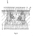
- each guide rail 30 is displaceably mounted between three guide plates 36, 37, 38.
- Two of these plates 36 are fixed to the bottom 14 of the recess 13 by means of screws 46, while two upper plates 37 are fixed to the cover plate 19 by means of screws 47.
- Two further plates 38 are each let into the side surface 39 of the guide rails 30, which is provided with grooves (unspecified) for this purpose.
- the lateral plates 38 and the guide rails 30 are firmly screwed together.
- the upper and lower plates 36 , 37 are provided with sliding elements 56 on their sliding or friction surfaces facing the guide rail 30 .
- Such sliding elements 56 are also introduced into the outer surfaces of the lateral guide plates 38 facing the clamping plate 12 .
- the guide plates 36, 37, 38 have the advantage that the guide rails 30 are always guided precisely and reliably within the clamping plate 12, while the sliding elements 56 ensure low friction and correspondingly low wear.
- a diamond-like material can also be used for the components mentioned, in which case the sliding surfaces can advantageously be polished for the reasons already mentioned above.
- the self-lubricating material can be an alloy of lead, tin, aluminum or copper, or a sintered metal. It is important that the material has self-lubricating properties in order to reduce the relatively high friction on the sliding surfaces. At the same time, the material must be resistant so that the self-lubricating properties are retained for as long as possible.
- the shut-off needles 16 are inserted from above in the center of the longitudinal axis A into the lifting plate 20, which is provided with bores (unspecified) for this purpose.
- each needle 16 has a thread at the end, which is screwed into a (not visible) essentially rectangular holding plate.
- An adjusting nut 18 fixes the needle 16 in relation to the holding plate, which lies flat on the lifting plate 20. In this way, the needles 16 are individually adjustable in length along the second direction R2 relative to the lifting plate 20 .
- Each holding plate lies in a recess (also not shown) whose height corresponds almost exactly to the height of the holding plate and whose external dimensions are larger than those of the holding plate, so that the holding plate can move radially within the recess.
- a cover plate 25 fastened to the lifting plate 20 by means of screws 26 secures the retaining plate in the recess.
- the retaining plate is thus fixed in the axial direction of the shut-off needles 16 with the least possible play between the lifting plate 20 and the cover plate 25, so that all the needles 16 can always be precisely brought into the closed position and opened again.
- the retaining plates are mounted in a floating manner, so that deflections of the needles 16 within the hot runner nozzles are compensated for during the lifting movements. Due to the rectangular shape of the holding plate, the needles 16 are also arranged in a rotationally fixed manner relative to the lifting plate 20 .
- the needles 16 protrude through the cover plates 25 with their adjusting nuts 18 . So that the ends of the needles do not protrude too far beyond the lifting plate 20, the holding plates and the cover plates 25 lie in depressions 24. The overall height of the actuating device 10 thus remains extremely small.
- a central recess 70 is introduced in the center between the depressions 24 in the lifting plate 20 and continues in the clamping plate 12 with the same inner diameter.
- the recess 70 serves to pass through a flow channel, a distributor arm or the like, in particular a machine nozzle (not shown) or a sprue bush, which supplies the distributor plate located below the clamping plate 12 with the plastic mass to be processed.
- the (unspecified) inner diameter of the recess 70 is dimensioned so that the lifting plate 20 can move freely.
- the end of the actuating device 10 forms a cover plate 19 (see 2 ) which lies flat on the guide rails 90 and is secured to them by means of screws 99.
- the cover plate 19 closes flush with the upper side of the clamping plate 12, so that the actuating device 10 does not protrude beyond the clamping plate 12. Rather, the device 10 is almost completely integrated in the clamping plate 12, which has an extremely favorable effect on the overall height of the tool. Only the drive 80 sits outside on the side of the clamping plate 12, but this has no effect on its overall height.
- shut-off needles 16 of a nozzle group are attached to the lifting element 20 .
- the number of shut-off needles 16 can easily be increased by making the lifting plate 20 correspondingly longer or wider.
- the shut-off needles 16 do not necessarily have to be arranged on the longitudinal axis A. For optimal utilization of the given mold surface, several mold inserts and thus several needle shut-off nozzles can be placed very close to one another, with the nozzles being combined into nozzle groups if necessary.
- the clamping plate 12 is provided with two adjacent depressions 13 or with a common depression, so that the control rails 30 and the guide rails 90 of the individual actuating devices 10 lie parallel to one another.
- control rails 30 and the pushing element 82 can also be connected to one another in a non-positive manner, for example by means of latching elements (not shown).
- control rails 30 and the thrust element 82 can also be designed in one piece, so that the U-shaped frame can be assembled or disassembled as a whole.
- the sliding and guiding elements 35, 36, 37, 38, 50, 60, 62 do not have to be coated directly with the self-lubricating material or alternatively with the diamond-like material.
- the corresponding material can also be applied to an intermediate carrier, eg a plate-shaped support element, and fixed to the friction surfaces of the sliding and guide elements 35, 36, 37, 38, 50, 60, 62, for example by screwing, latching or gluing.
Landscapes
- Engineering & Computer Science (AREA)
- Manufacturing & Machinery (AREA)
- Mechanical Engineering (AREA)
- Moulds For Moulding Plastics Or The Like (AREA)
- Injection Moulding Of Plastics Or The Like (AREA)
- Knitting Machines (AREA)
- Slide Fasteners (AREA)
Claims (32)
- Dispositif d'actionnement (10) pour des pointeaux de vannes dans des outils de moulage par injection comportant des busesa) avec des vannes à pointeaux,b) avec un élément de levée (20) sur lequel au moins deux pointeaux de vannes (16) de deux buses avec des vannes à pointeaux peuvent être fixés et qui est déplaçable entre deux rails de commande (30), montés de façon coulissante longitudinalement dans une première direction (R1), dans une deuxième direction (R2) s'étendant transversalement à la première direction (R1), etc) avec au moins deux éléments de glissement (50), qui convertissent un mouvement des rails de commande (30) le long de la première direction (R1) en un mouvement de levée de l'élément de levée (20) dans la deuxième direction (R2),d) l'élément de levée (20) étant disposé en longueur entre les rails de commande (30),e) les éléments de glissement (50) étant disposés entre l'élément de levée (20) et les rails de commande (30), dans des rainures (40) s'étendant en oblique par rapport à la première direction (R1) et à la deuxième direction (R2), caractérisé en ce quef) les rails de commande (30) et/ou les éléments de glissement (50), étant des composants déplacés les uns par rapport aux autres et dès lors soumis à l'usure, sont fabriqués au moins en partie en un matériau autolubrifiant ou un matériau diamantin ou sont revêtus au moins en partie avec un matériau autolubrifiant ou un matériau diamantin, etg) les éléments de glissement (50) sont insérés latéralement dans l'élément de levée (20)..
- Dispositif d'actionnement selon la revendication 1, caractérisé en ce que la longueur (L) des éléments de glissement (50) est plus grande que l'épaisseur (D) de l'élément de levée (20).
- Dispositif d'actionnement selon l'une quelconque des revendications 1 à 2, caractérisé en ce que l'élément de levée (20) est en guidage forcé dans la deuxième direction (R2).
- Dispositif d'actionnement selon la revendication 3, caractérisé en ce que l'élément de levée (20) est disposé entre deux butées (60, 62).
- Dispositif d'actionnement selon la revendication 3 ou 4, caractérisé en ce que les butées (60, 62) sont fabriquées au moins en partie en un matériau autolubrifiant ou un matériau diamantin ou sont revêtues au moins en partie avec un matériau autolubrifiant ou un matériau diamantin.
- Dispositif d'actionnement selon l'une quelconque des revendications 1 à 5, caractérisé en ce que les pointeaux de vannes (16) sont réglables par rapport à l'élément de levée (20) le long de la deuxième direction (R2).
- Dispositif d'actionnement selon l'une quelconque des revendications 1 à 6, caractérisé en ce que les pointeaux de vannes (16) sont axialement fixes et peuvent être tenus de façon radialement flottante sur la plaque de levée (20).
- Dispositif d'actionnement selon l'une quelconque des revendications 1 à 7, caractérisé en ce que l'élément de levée (20) présente au moins un évidement (70) pour le passage d'un canal d'écoulement, d'un bras de distributeur ou analogue de l'outil de moulage par injection.
- Dispositif d'actionnement selon l'une quelconque des revendications 1 à 8, caractérisé en ce que les rails de commande (30) sont reliés à un entraînement (80).
- Dispositif d'actionnement selon la revendication 9, caractérisé en ce que les rails de commande (30) sont reliés à l'entraînement (80) par un élément de poussée commun (82).
- Dispositif d'actionnement selon la revendication 9 ou 10, caractérisé en ce que les rails de commande (30) et l'élément de poussée (82) forment un cadre en forme de U.
- Dispositif d'actionnement selon l'une quelconque des revendications 9 à 11, caractérisé en ce que les rails de commande (30) et l'élément de poussée (82) sont assemblés l'un à l'autre par complémentarité de force et/ou de forme.
- Dispositif d'actionnement selon l'une quelconque des revendications 9 à 11, caractérisé en ce que les rails de commande (30) et l'élément de poussée (82) sont d'une seule pièce.
- Dispositif d'actionnement selon l'une quelconque des revendications 1 à 13, caractérisé en ce que les rails de commande (30) sont guidés de façon glissante entre des éléments de guidage (36, 37, 38, 90).
- Dispositif d'actionnement selon la revendication 14, caractérisé en ce que les éléments de guidage sont deux rails de guidage (90).
- Dispositif d'actionnement selon la revendication 15, caractérisé en ce que les rails de guidage (90) sont fixés à ou dans une plaque de fixation (12).
- Dispositif d'actionnement selon la revendication 15 ou 16, caractérisé en ce que les rails de commande (30) présentent, sur leurs faces latérales (39) tournées vers les rails de guidage (90), des lattes de glissement (35) qui sont guidées de façon glissante dans des rainures (94) des rails de guidage (90).
- Dispositif d'actionnement selon l'une quelconque des revendications 14 à 16, caractérisé en ce que les lattes de glissement (35) sont fabriquées au moins en partie en un matériau autolubrifiant ou un matériau diamantin ou sont revêtues au moins en partie avec un matériau autolubrifiant ou un matériau diamantin.
- Dispositif d'actionnement selon la revendication 14, caractérisé en ce que les éléments de guidage sont des plaques de guidage (36, 37, 38).
- Dispositif d'actionnement selon la revendication 19, caractérisé en ce que les plaques de guidage (36, 37, 38) sont munies d'éléments de glissement (56).
- Dispositif d'actionnement selon la revendication 19 ou 20, caractérisé en ce que les plaques de guidage (36, 37, 38) et/ou les éléments de glissement (56) sont fabriqués au moins en partie en un matériau autolubrifiant ou un matériau diamantin ou sont revêtus au moins en partie avec un matériau autolubrifiant ou un matériau diamantin.
- Dispositif d'actionnement selon l'une quelconque des revendications 1 à 21, caractérisé en ce que le matériau autolubrifiant est un métal antifriction.
- Dispositif d'actionnement selon la revendication 24, caractérisé en ce que le matériau autolubrifiant est un alliage de plomb, d'étain, d'aluminium ou de cuivre ou un métal fritté.
- Dispositif d'actionnement selon la revendication 22 ou 23, caractérisé en ce que le matériau autolubrifiant est un bronze ou un bronze fritté.
- Dispositif d'actionnement selon l'une quelconque des revendications 1 à 21, caractérisé en ce que la surface du matériau diamantin est polie.
- Dispositif d'actionnement selon l'une quelconque des revendications précédentes, caractérisé en ce que des composants qui s'usent en raison du mouvement relatif, en particulier les éléments de glissement (50), sont disposés de façon remplaçable.
- Outil de moulage par injection comportant au moins un dispositif d'actionnement (10) selon l'une quelconque des revendications 1 à 26.
- Outil de moulage par injection selon la revendication 27, caractérisé en ce que le dispositif d'actionnement (10) est réalisé dans ou sur une plaque de fixation (12).
- Outil de moulage par injection selon la revendication 28, caractérisé en ce que la plaque de fixation (12) est munie d'un creux (13) destiné à recevoir le dispositif d'actionnement (10).
- Outil de moulage par injection selon l'une quelconque des revendications 27 à 29, caractérisé en ce que le dispositif d'actionnement (10) est logé à fleur de la plaque de fixation (12).
- Outil de moulage par injection selon l'une quelconque des revendications 27 à 30, caractérisé en ce qu'au moins deux dispositifs d'actionnement (10) sont disposés parallèlement l'un à côté de l'autre.
- Outil de moulage par injection selon la revendication 31, caractérisé en ce que les dispositifs d'actionnement (10) présentent un entraînement commun (80).
Applications Claiming Priority (2)
| Application Number | Priority Date | Filing Date | Title |
|---|---|---|---|
| DE202005020412U DE202005020412U1 (de) | 2005-12-28 | 2005-12-28 | Betätigungsvorrichtung für Verschlußnadeln in Spritzgießvorrichtungen mit Nadelverschlußdüsen |
| PCT/EP2006/011573 WO2007079836A1 (fr) | 2005-12-28 | 2006-12-01 | Dispositif d'actionnement de pointeaux de vannes dans des dispositifs de moulage par injection comportant des buses a vannes a pointeaux |
Publications (3)
| Publication Number | Publication Date |
|---|---|
| EP1943078A1 EP1943078A1 (fr) | 2008-07-16 |
| EP1943078B1 EP1943078B1 (fr) | 2012-01-18 |
| EP1943078B2 true EP1943078B2 (fr) | 2022-05-11 |
Family
ID=37776456
Family Applications (1)
| Application Number | Title | Priority Date | Filing Date |
|---|---|---|---|
| EP06829241.6A Active EP1943078B2 (fr) | 2005-12-28 | 2006-12-01 | Dispositif d'actionnement de pointeaux de vannes dans des dispositifs de moulage par injection comportant des buses a vannes a pointeaux |
Country Status (11)
| Country | Link |
|---|---|
| US (1) | US7815431B2 (fr) |
| EP (1) | EP1943078B2 (fr) |
| JP (1) | JP2009522128A (fr) |
| KR (1) | KR20080090468A (fr) |
| CN (1) | CN101351320A (fr) |
| AT (1) | ATE541689T1 (fr) |
| BR (1) | BRPI0621078A2 (fr) |
| CA (1) | CA2635710A1 (fr) |
| DE (1) | DE202005020412U1 (fr) |
| TW (1) | TW200726623A (fr) |
| WO (1) | WO2007079836A1 (fr) |
Families Citing this family (15)
| Publication number | Priority date | Publication date | Assignee | Title |
|---|---|---|---|---|
| US8220362B2 (en) * | 2007-10-23 | 2012-07-17 | Husky Injection Molding Systems Ltd. | Cam apparatus for valve stem actuation |
| DE102011106606B4 (de) * | 2011-06-16 | 2024-12-24 | Meusburger Georg GmbH & Co. KG | Vorrichtung zur gleichzeitigen Betätigung einer Vielzahl von Verschlussnadeln in einer Kunststoffspritzmaschine |
| CN102275266B (zh) * | 2011-08-11 | 2013-08-28 | 思柏精密模具注塑(无锡)有限公司 | 一种高精密件成型模具及成型方法 |
| DE102012003574A1 (de) | 2012-02-27 | 2013-05-02 | Otto Männer Innovation GmbH | Stelleinrichtung zum Verstellen der Nadelventile einer Heißkanal-Spritzgießvorrichtung |
| DE102015111415A1 (de) | 2015-07-14 | 2017-01-19 | Günther Heisskanaltechnik Gmbh | Werkzeughälfte für ein Formwerkzeug einer Spritzgießmaschine mit einem Heißkanalsystem |
| CN108367474B (zh) | 2015-11-23 | 2020-10-23 | 赫斯基注塑系统有限公司 | 阀杆致动 |
| CN107650338B (zh) * | 2016-07-26 | 2023-02-17 | 柳道万和(苏州)热流道系统有限公司 | 阀针驱动系统 |
| WO2018194961A1 (fr) * | 2017-04-18 | 2018-10-25 | Synventive Molding Solutions, Inc. | Entraînement de tige de soupape linéaire à linéaire pendant un cycle d'injection |
| DE102017125767A1 (de) | 2017-11-03 | 2019-05-23 | Günther Heisskanaltechnik Gmbh | Hubplattenantrieb für Nadelverschlusssysteme für Servomotoren |
| US10800082B2 (en) * | 2018-08-14 | 2020-10-13 | Otto Männer GmbH | Hot runner injection nozzle and drive train |
| TWI738544B (zh) * | 2020-10-21 | 2021-09-01 | 僑陽科技工業有限公司 | 七層軟管成型機構及製造方法 |
| DE102021111302A1 (de) | 2021-04-30 | 2022-11-03 | Günther Heisskanaltechnik Gmbh | Betätigungsvorrichtung für Verschlussnadeln in Spritzgießwerkzeugen mit Nadelverschlussdüsen |
| DE202021004643U1 (de) | 2021-04-30 | 2026-05-21 | Günther Heisskanaltechnik Gmbh | Betätigungsvorrichtung für Verschlussnadeln in Spritzgießwerkzeugen mit Nadelverschlussdüsen |
| DE102022112128A1 (de) | 2022-05-13 | 2023-11-16 | Günther Heisskanaltechnik Gmbh | Hubelement zur Betätigung von Verschlussnadeln und Betätigungsvorrichtung mit einem Hubelement |
| DE102022128796A1 (de) * | 2022-10-29 | 2024-05-16 | Günther Heisskanaltechnik Gmbh | Antriebseinheit für ein Spritzgusssystem und Spritzgusssystem mit einer Antriebseinheit |
Family Cites Families (22)
| Publication number | Priority date | Publication date | Assignee | Title |
|---|---|---|---|---|
| DE548823C (de) | 1930-10-08 | 1932-04-20 | I G Farbenindustrie Akt Ges | Verfahren zur Darstellung von Alkylmercaptoderivaten der 2-Oxynaphthalin-3-carbonsaeure |
| SE301380B (fr) * | 1965-11-10 | 1968-06-04 | Philips Nv | |
| GB1193074A (en) * | 1966-08-24 | 1970-05-28 | Prestincert Ltd | Improvements in or relating to Press Tools. |
| US3582157A (en) | 1968-09-09 | 1971-06-01 | Lempco Ind Inc | Bearing assembly having an interference-fit bearing surface of synthetic resin material |
| DE1906921A1 (de) | 1969-02-12 | 1970-09-03 | Geyer & Co | Spritzgussform |
| DE2357962A1 (de) | 1973-11-21 | 1975-05-28 | Zimmermann & Co Maschf | Vorrichtung zum rueckfuehren von auswerfern |
| FR2278473A1 (fr) | 1974-02-21 | 1976-02-13 | Materiel Applic Plastiques | Perfectionnements aux presses a mouler les matieres plastiques, notamment pour la fabrication de pieces plates |
| US4497621A (en) * | 1983-04-13 | 1985-02-05 | American Can Company | Apparatus for simultaneously driving valve means through co-injection nozzles of a multi-cavity injection molding machine |
| JPH0542568A (ja) | 1991-08-12 | 1993-02-23 | Japan Steel Works Ltd:The | 射出成形機の逆流防止装置 |
| DE9115966U1 (de) * | 1991-12-23 | 1992-03-05 | Ifw - Manfred Otte Gesellschaft Mbh & Co. Kg, Micheldorf | Spritzgußform |
| DE69317263T2 (de) * | 1993-04-30 | 1998-10-01 | Graphitech Inc | Enganliegende Schiebeanordnung aus einem Metallbauteil und einem Kunststoffverbundbauteil |
| DE19606045C2 (de) * | 1996-02-19 | 1997-11-27 | Krupp Ag Hoesch Krupp | Verfahren zum Spritzgießen von dreischichtigen Spritzlingen und Vorrichtung für die Durchführung des Verfahrens |
| DE19611880A1 (de) * | 1996-03-26 | 1997-10-02 | Zahoransky Formenbau Gmbh | Spritzgießwerkzeug |
| DE19720927A1 (de) | 1996-05-20 | 1997-11-27 | Hasco Normalien Hasenclever Co | Werkzeugform zum Druck- oder Spritzgießen von Metallen und/oder Kunststoffen |
| GB2343409B (en) | 1997-09-15 | 2000-10-18 | Electra Form Inc | Improved molded article retrieval apparatus |
| NL1008105C2 (nl) | 1998-01-23 | 1999-07-26 | Axxicon Moulds Eindhoven Bv | Spuitgietmatrijs. |
| DE69927362T2 (de) | 1998-03-13 | 2006-07-13 | Axxicon Moulds Eindhoven B.V. | Spritzgussmatrizze für scheibenartigen gegenstand aus kunststoff und mehrfach-spritzgiessform |
| JP2000190367A (ja) | 1998-12-28 | 2000-07-11 | S D R Kk | 樹脂射出成形機、樹脂溶融押出機等における摺動面を超耐磨耗表面処理したシリンダ、スクリュウの構造 |
| CA2261367C (fr) * | 1999-02-08 | 2008-04-22 | Mold-Masters Limited | Mecanisme d'actionnement d'elements de robinet de moulage par injection |
| US6755641B1 (en) | 2000-09-01 | 2004-06-29 | Mold-Masters Limited | Stack injection molding apparatus with separately actuated arrays of valve gates |
| SE516975C2 (sv) | 2001-02-21 | 2002-03-26 | Hans Mueller | Anordning vid hydraulisk tvåstegsutstötare |
| US7134868B2 (en) * | 2003-11-26 | 2006-11-14 | Mold-Masters Limited | Injection molding nozzle with wear-resistant tip having diamond-type coating |
-
2005
- 2005-12-28 DE DE202005020412U patent/DE202005020412U1/de not_active Expired - Lifetime
-
2006
- 2006-12-01 KR KR1020087018348A patent/KR20080090468A/ko not_active Withdrawn
- 2006-12-01 WO PCT/EP2006/011573 patent/WO2007079836A1/fr not_active Ceased
- 2006-12-01 EP EP06829241.6A patent/EP1943078B2/fr active Active
- 2006-12-01 CA CA 2635710 patent/CA2635710A1/fr not_active Abandoned
- 2006-12-01 US US12/087,205 patent/US7815431B2/en not_active Expired - Fee Related
- 2006-12-01 JP JP2008547865A patent/JP2009522128A/ja not_active Withdrawn
- 2006-12-01 CN CNA2006800500665A patent/CN101351320A/zh active Pending
- 2006-12-01 BR BRPI0621078-3A patent/BRPI0621078A2/pt not_active IP Right Cessation
- 2006-12-01 AT AT06829241T patent/ATE541689T1/de active
- 2006-12-04 TW TW095144875A patent/TW200726623A/zh unknown
Also Published As
| Publication number | Publication date |
|---|---|
| TW200726623A (en) | 2007-07-16 |
| JP2009522128A (ja) | 2009-06-11 |
| US20090017154A1 (en) | 2009-01-15 |
| KR20080090468A (ko) | 2008-10-08 |
| CN101351320A (zh) | 2009-01-21 |
| CA2635710A1 (fr) | 2007-07-19 |
| EP1943078B1 (fr) | 2012-01-18 |
| BRPI0621078A2 (pt) | 2011-11-29 |
| DE202005020412U1 (de) | 2007-05-10 |
| WO2007079836A1 (fr) | 2007-07-19 |
| ATE541689T1 (de) | 2012-02-15 |
| EP1943078A1 (fr) | 2008-07-16 |
| US7815431B2 (en) | 2010-10-19 |
Similar Documents
| Publication | Publication Date | Title |
|---|---|---|
| EP1943078B1 (fr) | Dispositif d'actionnement de pointeaux de vannes dans des dispositifs de moulage par injection comportant des buses a vannes a pointeaux | |
| EP0635350B1 (fr) | Dispositif de commande pneumatique pour des valves à aiguille de canal chauffant pour moules d'injection | |
| DE69916775T2 (de) | Betätigungsmechanismus für ein Ventilteil einer Spritzgiessvorrichtung | |
| DE60316444T2 (de) | Ventilnadelführungs- und -ausrichtungssystem für einen heisskanal in einer spritzgiessvorrichtung | |
| DE102009053503B4 (de) | Spritzgießvorrichtung mit einer Ventilnadelkupplung | |
| DE2940044C2 (fr) | ||
| DE102011106606B4 (de) | Vorrichtung zur gleichzeitigen Betätigung einer Vielzahl von Verschlussnadeln in einer Kunststoffspritzmaschine | |
| DE60102988T2 (de) | Etagenspritzgiessvorrichtung mit getrenntangetriebenen Anordnungen von Ventilanschnitten | |
| EP2427317B1 (fr) | Buse chaude d'injection latérale | |
| DE19857735B4 (de) | Stell- und Regelvorrichtung für einen Heiß- oder Kaltkanal eines Kunststoff-Formwerkzeuges | |
| DE102008028577A1 (de) | Eckenangussdüse | |
| DE3523828C1 (de) | Biegevorrichtung zur Herstellung von aus Draht- oder Bandabschnitten bestehenden Formteilen | |
| EP3117977B1 (fr) | Moitie d'outil pour un moule de formage d'une machine a mouler par injection comprenant un systeme de canaux chauffants | |
| EP1971473B1 (fr) | Dispositif d'actionnement d'aiguilles d'obturation dans des dispositifs de moulage par injection comportant des buses avec obturateurs a aiguilles | |
| AT526463B1 (de) | Heißkanalwerkzeug, Spritzgussvorrichtung und Herstellungsverfahren | |
| EP1973722B1 (fr) | Dispositif d'actionnement de pointeaux de fermeture dans des dispositifs de moulage par injection dotes d'ajutages fermes par pointeau | |
| EP1477292B1 (fr) | Buse d'injection pour presses à injecter | |
| EP3760407B1 (fr) | Outil de moulage par injection destiné à la fabrication de pièces moulées par injection | |
| DE202006008988U1 (de) | Spritzgießwerkzeug mit Nadelverschlussdüsen | |
| DE10308613A1 (de) | Ventil mit einem Hebel, Hebel und Verfahren zur Herstellung eines Hebels | |
| DE102023130949A1 (de) | Werkzeug zum Spritzgießen von Kunststoffteilen und Verfahren zu dessen Betrieb | |
| DE202006000373U1 (de) | Betätigungsvorrichtung für Verschlußnadeln in Spritzgießvorrichtungen mit Nadelverschlußdüsen | |
| DE202024103987U1 (de) | Schiebereinheit eines Formwerkzeuges | |
| DE202006014168U1 (de) | Betätigungsvorrichtung für Verschlussnadeln in Spritzgießvorrichtungen mit Nadelverschlussdüsen | |
| HK1124807A (en) | Actuating device for shut-off needles in injection moulding devices comprising needle shut-off nozzles |
Legal Events
| Date | Code | Title | Description |
|---|---|---|---|
| PUAI | Public reference made under article 153(3) epc to a published international application that has entered the european phase |
Free format text: ORIGINAL CODE: 0009012 |
|
| 17P | Request for examination filed |
Effective date: 20080331 |
|
| AK | Designated contracting states |
Kind code of ref document: A1 Designated state(s): AT BE BG CH CY CZ DE DK EE ES FI FR GB GR HU IE IS IT LI LT LU LV MC NL PL PT RO SE SI SK TR |
|
| 17Q | First examination report despatched |
Effective date: 20080805 |
|
| GRAP | Despatch of communication of intention to grant a patent |
Free format text: ORIGINAL CODE: EPIDOSNIGR1 |
|
| GRAS | Grant fee paid |
Free format text: ORIGINAL CODE: EPIDOSNIGR3 |
|
| GRAA | (expected) grant |
Free format text: ORIGINAL CODE: 0009210 |
|
| AK | Designated contracting states |
Kind code of ref document: B1 Designated state(s): AT BE BG CH CY CZ DE DK EE ES FI FR GB GR HU IE IS IT LI LT LU LV MC NL PL PT RO SE SI SK TR |
|
| DAX | Request for extension of the european patent (deleted) | ||
| REG | Reference to a national code |
Ref country code: GB Ref legal event code: FG4D Free format text: NOT ENGLISH |
|
| REG | Reference to a national code |
Ref country code: CH Ref legal event code: EP |
|
| REG | Reference to a national code |
Ref country code: IE Ref legal event code: FG4D Free format text: LANGUAGE OF EP DOCUMENT: GERMAN Ref country code: AT Ref legal event code: REF Ref document number: 541689 Country of ref document: AT Kind code of ref document: T Effective date: 20120215 |
|
| REG | Reference to a national code |
Ref country code: DE Ref legal event code: R096 Ref document number: 502006010902 Country of ref document: DE Effective date: 20120315 |
|
| REG | Reference to a national code |
Ref country code: NL Ref legal event code: T3 |
|
| LTIE | Lt: invalidation of european patent or patent extension |
Effective date: 20120118 |
|
| PG25 | Lapsed in a contracting state [announced via postgrant information from national office to epo] |
Ref country code: IS Free format text: LAPSE BECAUSE OF FAILURE TO SUBMIT A TRANSLATION OF THE DESCRIPTION OR TO PAY THE FEE WITHIN THE PRESCRIBED TIME-LIMIT Effective date: 20120518 Ref country code: LT Free format text: LAPSE BECAUSE OF FAILURE TO SUBMIT A TRANSLATION OF THE DESCRIPTION OR TO PAY THE FEE WITHIN THE PRESCRIBED TIME-LIMIT Effective date: 20120118 Ref country code: BG Free format text: LAPSE BECAUSE OF FAILURE TO SUBMIT A TRANSLATION OF THE DESCRIPTION OR TO PAY THE FEE WITHIN THE PRESCRIBED TIME-LIMIT Effective date: 20120418 |
|
| REG | Reference to a national code |
Ref country code: IE Ref legal event code: FD4D |
|
| PG25 | Lapsed in a contracting state [announced via postgrant information from national office to epo] |
Ref country code: PL Free format text: LAPSE BECAUSE OF FAILURE TO SUBMIT A TRANSLATION OF THE DESCRIPTION OR TO PAY THE FEE WITHIN THE PRESCRIBED TIME-LIMIT Effective date: 20120118 Ref country code: FI Free format text: LAPSE BECAUSE OF FAILURE TO SUBMIT A TRANSLATION OF THE DESCRIPTION OR TO PAY THE FEE WITHIN THE PRESCRIBED TIME-LIMIT Effective date: 20120118 Ref country code: LV Free format text: LAPSE BECAUSE OF FAILURE TO SUBMIT A TRANSLATION OF THE DESCRIPTION OR TO PAY THE FEE WITHIN THE PRESCRIBED TIME-LIMIT Effective date: 20120118 Ref country code: GR Free format text: LAPSE BECAUSE OF FAILURE TO SUBMIT A TRANSLATION OF THE DESCRIPTION OR TO PAY THE FEE WITHIN THE PRESCRIBED TIME-LIMIT Effective date: 20120419 Ref country code: PT Free format text: LAPSE BECAUSE OF FAILURE TO SUBMIT A TRANSLATION OF THE DESCRIPTION OR TO PAY THE FEE WITHIN THE PRESCRIBED TIME-LIMIT Effective date: 20120518 |
|
| PG25 | Lapsed in a contracting state [announced via postgrant information from national office to epo] |
Ref country code: CY Free format text: LAPSE BECAUSE OF FAILURE TO SUBMIT A TRANSLATION OF THE DESCRIPTION OR TO PAY THE FEE WITHIN THE PRESCRIBED TIME-LIMIT Effective date: 20120118 |
|
| PLBI | Opposition filed |
Free format text: ORIGINAL CODE: 0009260 |
|
| PG25 | Lapsed in a contracting state [announced via postgrant information from national office to epo] |
Ref country code: EE Free format text: LAPSE BECAUSE OF FAILURE TO SUBMIT A TRANSLATION OF THE DESCRIPTION OR TO PAY THE FEE WITHIN THE PRESCRIBED TIME-LIMIT Effective date: 20120118 Ref country code: SI Free format text: LAPSE BECAUSE OF FAILURE TO SUBMIT A TRANSLATION OF THE DESCRIPTION OR TO PAY THE FEE WITHIN THE PRESCRIBED TIME-LIMIT Effective date: 20120118 Ref country code: DK Free format text: LAPSE BECAUSE OF FAILURE TO SUBMIT A TRANSLATION OF THE DESCRIPTION OR TO PAY THE FEE WITHIN THE PRESCRIBED TIME-LIMIT Effective date: 20120118 Ref country code: CZ Free format text: LAPSE BECAUSE OF FAILURE TO SUBMIT A TRANSLATION OF THE DESCRIPTION OR TO PAY THE FEE WITHIN THE PRESCRIBED TIME-LIMIT Effective date: 20120118 Ref country code: RO Free format text: LAPSE BECAUSE OF FAILURE TO SUBMIT A TRANSLATION OF THE DESCRIPTION OR TO PAY THE FEE WITHIN THE PRESCRIBED TIME-LIMIT Effective date: 20120118 Ref country code: SE Free format text: LAPSE BECAUSE OF FAILURE TO SUBMIT A TRANSLATION OF THE DESCRIPTION OR TO PAY THE FEE WITHIN THE PRESCRIBED TIME-LIMIT Effective date: 20120118 Ref country code: IE Free format text: LAPSE BECAUSE OF FAILURE TO SUBMIT A TRANSLATION OF THE DESCRIPTION OR TO PAY THE FEE WITHIN THE PRESCRIBED TIME-LIMIT Effective date: 20120118 |
|
| PLAX | Notice of opposition and request to file observation + time limit sent |
Free format text: ORIGINAL CODE: EPIDOSNOBS2 |
|
| 26 | Opposition filed |
Opponent name: EWIKON HEISSKANALSYSTEME GMBH & CO. KG Effective date: 20121018 |
|
| PG25 | Lapsed in a contracting state [announced via postgrant information from national office to epo] |
Ref country code: SK Free format text: LAPSE BECAUSE OF FAILURE TO SUBMIT A TRANSLATION OF THE DESCRIPTION OR TO PAY THE FEE WITHIN THE PRESCRIBED TIME-LIMIT Effective date: 20120118 |
|
| REG | Reference to a national code |
Ref country code: DE Ref legal event code: R026 Ref document number: 502006010902 Country of ref document: DE Effective date: 20121018 |
|
| PGFP | Annual fee paid to national office [announced via postgrant information from national office to epo] |
Ref country code: CH Payment date: 20121221 Year of fee payment: 7 |
|
| PLAF | Information modified related to communication of a notice of opposition and request to file observations + time limit |
Free format text: ORIGINAL CODE: EPIDOSCOBS2 |
|
| PG25 | Lapsed in a contracting state [announced via postgrant information from national office to epo] |
Ref country code: ES Free format text: LAPSE BECAUSE OF FAILURE TO SUBMIT A TRANSLATION OF THE DESCRIPTION OR TO PAY THE FEE WITHIN THE PRESCRIBED TIME-LIMIT Effective date: 20120429 |
|
| PGFP | Annual fee paid to national office [announced via postgrant information from national office to epo] |
Ref country code: BE Payment date: 20121219 Year of fee payment: 7 |
|
| PLBB | Reply of patent proprietor to notice(s) of opposition received |
Free format text: ORIGINAL CODE: EPIDOSNOBS3 |
|
| PG25 | Lapsed in a contracting state [announced via postgrant information from national office to epo] |
Ref country code: MC Free format text: LAPSE BECAUSE OF NON-PAYMENT OF DUE FEES Effective date: 20121231 |
|
| PG25 | Lapsed in a contracting state [announced via postgrant information from national office to epo] |
Ref country code: TR Free format text: LAPSE BECAUSE OF FAILURE TO SUBMIT A TRANSLATION OF THE DESCRIPTION OR TO PAY THE FEE WITHIN THE PRESCRIBED TIME-LIMIT Effective date: 20120118 |
|
| PG25 | Lapsed in a contracting state [announced via postgrant information from national office to epo] |
Ref country code: LU Free format text: LAPSE BECAUSE OF NON-PAYMENT OF DUE FEES Effective date: 20121201 |
|
| BERE | Be: lapsed |
Owner name: GUNTHER HEISSKANALTECHNIK G.M.B.H. Effective date: 20131231 |
|
| PG25 | Lapsed in a contracting state [announced via postgrant information from national office to epo] |
Ref country code: HU Free format text: LAPSE BECAUSE OF FAILURE TO SUBMIT A TRANSLATION OF THE DESCRIPTION OR TO PAY THE FEE WITHIN THE PRESCRIBED TIME-LIMIT Effective date: 20061201 |
|
| REG | Reference to a national code |
Ref country code: CH Ref legal event code: PL |
|
| PG25 | Lapsed in a contracting state [announced via postgrant information from national office to epo] |
Ref country code: BE Free format text: LAPSE BECAUSE OF NON-PAYMENT OF DUE FEES Effective date: 20131231 Ref country code: LI Free format text: LAPSE BECAUSE OF NON-PAYMENT OF DUE FEES Effective date: 20131231 Ref country code: CH Free format text: LAPSE BECAUSE OF NON-PAYMENT OF DUE FEES Effective date: 20131231 |
|
| APBM | Appeal reference recorded |
Free format text: ORIGINAL CODE: EPIDOSNREFNO |
|
| APBP | Date of receipt of notice of appeal recorded |
Free format text: ORIGINAL CODE: EPIDOSNNOA2O |
|
| APAH | Appeal reference modified |
Free format text: ORIGINAL CODE: EPIDOSCREFNO |
|
| APBQ | Date of receipt of statement of grounds of appeal recorded |
Free format text: ORIGINAL CODE: EPIDOSNNOA3O |
|
| REG | Reference to a national code |
Ref country code: FR Ref legal event code: PLFP Year of fee payment: 10 |
|
| REG | Reference to a national code |
Ref country code: FR Ref legal event code: PLFP Year of fee payment: 11 |
|
| REG | Reference to a national code |
Ref country code: FR Ref legal event code: PLFP Year of fee payment: 12 |
|
| APBU | Appeal procedure closed |
Free format text: ORIGINAL CODE: EPIDOSNNOA9O |
|
| PLAH | Information related to despatch of examination report in opposition + time limit modified |
Free format text: ORIGINAL CODE: EPIDOSCORE2 |
|
| PLAY | Examination report in opposition despatched + time limit |
Free format text: ORIGINAL CODE: EPIDOSNORE2 |
|
| PLAH | Information related to despatch of examination report in opposition + time limit modified |
Free format text: ORIGINAL CODE: EPIDOSCORE2 |
|
| PLBC | Reply to examination report in opposition received |
Free format text: ORIGINAL CODE: EPIDOSNORE3 |
|
| RIC2 | Information provided on ipc code assigned after grant |
Ipc: B29C 45/28 20060101AFI20200914BHEP Ipc: B29C 45/83 20060101ALN20200914BHEP |
|
| PGFP | Annual fee paid to national office [announced via postgrant information from national office to epo] |
Ref country code: NL Payment date: 20211221 Year of fee payment: 16 |
|
| PUAH | Patent maintained in amended form |
Free format text: ORIGINAL CODE: 0009272 |
|
| STAA | Information on the status of an ep patent application or granted ep patent |
Free format text: STATUS: PATENT MAINTAINED AS AMENDED |
|
| 27A | Patent maintained in amended form |
Effective date: 20220511 |
|
| AK | Designated contracting states |
Kind code of ref document: B2 Designated state(s): AT BE BG CH CY CZ DE DK EE ES FI FR GB GR HU IE IS IT LI LT LU LV MC NL PL PT RO SE SI SK TR |
|
| REG | Reference to a national code |
Ref country code: DE Ref legal event code: R102 Ref document number: 502006010902 Country of ref document: DE |
|
| PGFP | Annual fee paid to national office [announced via postgrant information from national office to epo] |
Ref country code: IT Payment date: 20211224 Year of fee payment: 16 |
|
| REG | Reference to a national code |
Ref country code: NL Ref legal event code: MP Effective date: 20120118 |
|
| PG25 | Lapsed in a contracting state [announced via postgrant information from national office to epo] |
Ref country code: NL Free format text: LAPSE BECAUSE OF FAILURE TO SUBMIT A TRANSLATION OF THE DESCRIPTION OR TO PAY THE FEE WITHIN THE PRESCRIBED TIME-LIMIT Effective date: 20120118 |
|
| PGFP | Annual fee paid to national office [announced via postgrant information from national office to epo] |
Ref country code: GB Payment date: 20221222 Year of fee payment: 17 Ref country code: FR Payment date: 20221222 Year of fee payment: 17 Ref country code: AT Payment date: 20221222 Year of fee payment: 17 |
|
| REG | Reference to a national code |
Ref country code: DE Ref legal event code: R082 Ref document number: 502006010902 Country of ref document: DE Representative=s name: PATENTANWAELTE OLBRICHT, BUCHHOLD, KEULERTZ PA, DE |
|
| PG25 | Lapsed in a contracting state [announced via postgrant information from national office to epo] |
Ref country code: IT Free format text: LAPSE BECAUSE OF NON-PAYMENT OF DUE FEES Effective date: 20221201 |
|
| REG | Reference to a national code |
Ref country code: AT Ref legal event code: MM01 Ref document number: 541689 Country of ref document: AT Kind code of ref document: T Effective date: 20231201 |
|
| GBPC | Gb: european patent ceased through non-payment of renewal fee |
Effective date: 20231201 |
|
| PG25 | Lapsed in a contracting state [announced via postgrant information from national office to epo] |
Ref country code: GB Free format text: LAPSE BECAUSE OF NON-PAYMENT OF DUE FEES Effective date: 20231201 |
|
| PG25 | Lapsed in a contracting state [announced via postgrant information from national office to epo] |
Ref country code: FR Free format text: LAPSE BECAUSE OF NON-PAYMENT OF DUE FEES Effective date: 20231231 |
|
| PG25 | Lapsed in a contracting state [announced via postgrant information from national office to epo] |
Ref country code: AT Free format text: LAPSE BECAUSE OF NON-PAYMENT OF DUE FEES Effective date: 20231201 |
|
| PG25 | Lapsed in a contracting state [announced via postgrant information from national office to epo] |
Ref country code: GB Free format text: LAPSE BECAUSE OF NON-PAYMENT OF DUE FEES Effective date: 20231201 Ref country code: FR Free format text: LAPSE BECAUSE OF NON-PAYMENT OF DUE FEES Effective date: 20231231 Ref country code: AT Free format text: LAPSE BECAUSE OF NON-PAYMENT OF DUE FEES Effective date: 20231201 |
|
| PGFP | Annual fee paid to national office [announced via postgrant information from national office to epo] |
Ref country code: DE Payment date: 20241231 Year of fee payment: 19 |