EP1943106B1 - Verfahren zum zusammenfügen mehrerer seiten - Google Patents
Verfahren zum zusammenfügen mehrerer seiten Download PDFInfo
- Publication number
- EP1943106B1 EP1943106B1 EP06807139A EP06807139A EP1943106B1 EP 1943106 B1 EP1943106 B1 EP 1943106B1 EP 06807139 A EP06807139 A EP 06807139A EP 06807139 A EP06807139 A EP 06807139A EP 1943106 B1 EP1943106 B1 EP 1943106B1
- Authority
- EP
- European Patent Office
- Prior art keywords
- sheet
- point
- cut
- motif
- slit
- Prior art date
- Legal status (The legal status is an assumption and is not a legal conclusion. Google has not performed a legal analysis and makes no representation as to the accuracy of the status listed.)
- Not-in-force
Links
- 238000000034 method Methods 0.000 title claims abstract description 27
- 238000005520 cutting process Methods 0.000 claims abstract description 66
- 230000002745 absorbent Effects 0.000 claims description 12
- 239000002250 absorbent Substances 0.000 claims description 12
- 239000011159 matrix material Substances 0.000 claims description 10
- 230000002093 peripheral effect Effects 0.000 claims description 8
- 238000002679 ablation Methods 0.000 claims description 4
- 230000000149 penetrating effect Effects 0.000 claims description 4
- 241000208140 Acer Species 0.000 claims 1
- 238000004590 computer program Methods 0.000 abstract description 4
- 230000015572 biosynthetic process Effects 0.000 description 7
- 238000003780 insertion Methods 0.000 description 4
- 230000037431 insertion Effects 0.000 description 4
- 230000003287 optical effect Effects 0.000 description 2
- 238000003860 storage Methods 0.000 description 2
- 210000002105 tongue Anatomy 0.000 description 2
- 238000004026 adhesive bonding Methods 0.000 description 1
- 230000000712 assembly Effects 0.000 description 1
- 238000000429 assembly Methods 0.000 description 1
- 238000012550 audit Methods 0.000 description 1
- 230000006378 damage Effects 0.000 description 1
- 238000006073 displacement reaction Methods 0.000 description 1
- 230000000694 effects Effects 0.000 description 1
- 238000005304 joining Methods 0.000 description 1
- 230000005291 magnetic effect Effects 0.000 description 1
- 230000015654 memory Effects 0.000 description 1
- 229910052751 metal Inorganic materials 0.000 description 1
- 230000005855 radiation Effects 0.000 description 1
Images


Classifications
-
- B—PERFORMING OPERATIONS; TRANSPORTING
- B42—BOOKBINDING; ALBUMS; FILES; SPECIAL PRINTED MATTER
- B42F—SHEETS TEMPORARILY ATTACHED TOGETHER; FILING APPLIANCES; FILE CARDS; INDEXING
- B42F1/00—Sheets temporarily attached together without perforating; Means therefor
Definitions
- the invention relates to a method for assembling at least two pages together so as to obtain a bound document. This method can be applied in many fields that require the assembly of several pages to form a document, particularly in the field of the secretariat.
- the present invention provides a simple way to realize the assembly of pages to form a complete document, without using the assembly means of the prior art.
- the invention proposes to use a cutting and printing device, for example a device such as that disclosed in document [1] referenced at the end of the description, to obtain a solution "all paper” to assemble the pages together.
- a "slit” is a cut made inside the surface of a leaf, with a uncut space on both sides of the slit-shaped cutout.
- this space has a value greater than or equal to 5 mm.
- the slit cutting is stopped at a distance greater than or equal to 5 mm from one of the edges of the sheet.
- the two cutouts on either side of a central part of the "male” cutting pattern make it possible to form tongues which will be inserted into the slot of the "female” cutting pattern and prevent the exit of the cutting pattern "Male” of the "female” cutting pattern.
- the blanks are placed in an unprinted space (text, drawings ...) of the sheet, for example in the margin outside the printed text, so that the reading of the sheets is not hindered by the presence of the cuts.
- a single sheet comprising one or more "female” type cutting patterns and all other sheets comprising one or more "male” type cutting patterns, or vice versa, and the sheet comprising the single type of patterns. may constitute the first page of the assembled document or the last page of this document.
- the assembly method further comprises a step of forming at least one fold line, using the cutting means of the peripheral device, starting from point C and / or point D and going towards the edge. of the second sheet so as to facilitate the insertion of the "male” cut, the sheet being folded along the fold line or lines in the "female” cutout. It is recalled that folding is a cut at half-flesh of the thickness of the sheet.
- the fold line starting from point C (of point D) forms an obtuse angle with the cutoff starting from point C (of point D), said obtuse angle being between 90 ° and 135 °.
- This angle value makes it easy to insert (for example by sliding) the "male” cutting pattern into the “female” cutting pattern, by manually folding the sheet comprising the "male” pattern along the fold lines. Once inserted, the "male” cut pattern can be unfolded so that the “male” cut pattern forms tabs that prevent the "male” pattern from escaping the "female” pattern.
- the "male" cutting pattern comprises two fold lines, a fold line starting from the point C and a fold line starting from the point D.
- the assembly method further comprises a step of forming at least one cut-out starting from the slit-shaped female pattern of a point situated between the points A and B and going towards the outside of the sheet.
- the slot comprises a single cutout equidistant from point A and point B.
- the slot comprises two cutouts, a first cut starting from the point A 'situated on the slot and the second cutting starting from the point B' situated on the slot, the distances AA 'and BB' being equal.
- the margin that is to say the space between the cutting line and a printed area, for two consecutive sheets is less than or equal to the thickness of one of the two sheets.
- This margin can also be zero. This can create a "white borderless" effect, particularly elegant and have, for example, a photograph, an illustration or a table of large data printed on a double page.
- the determined location of the at least one "female” cutting pattern is also located near a corner of the sheet.
- the "corner” is where two adjacent edges of a leaf join.
- the slot of the "female" cutting pattern is a straight line from point A to point B.
- all the cuts may be made in straight lines or curves.
- the cut-out (s) on each sheet are produced by printing the pattern of the cut on the sheet in question using an absorbent ink capable of penetrating deeply into said sheet of paper, then by exposing said sheet to beam of a low-power laser emitting, according to instructions received, a wavelength absorbed by the ink-inked places, the power of the laser being sufficient to obtain the cutting of the sheet of paper at the places inked.
- said at least one fold line on a sheet is made by printing said at least one fold line on the sheet in question using an absorbent ink capable of penetrating deeply into said sheet of paper, then by exposing said sheet to the beam of a low power laser emitting, according to received instructions, a wavelength absorbed by the locations inked in absorbent ink, the power of the laser being sufficient to obtain ablation partial paper at said locations inked in absorbent ink.
- Partial ablation of the paper makes it easy to fold the sheet of paper at the fold line, but without the sheet of paper being cut at that fold line.
- the laser is one of the lasers of a matrix of lasers comprising several lasers, each laser being controlled individually.
- a matrix of lasers that is to say a matrix comprising several lasers, each laser of the matrix being controlled individually so as to emit radiation when pass in front of an area to be removed.
- Such a matrix may comprise one or more hundreds of laser diodes. It can for example be achieved by assembling several diode bars.
- the use of a matrix of lasers instead of a single laser allows thus to avoid that the cutting takes place in a paper handling phase subsequent to the inking phase, and consists of following with the matrix of lasers the cutting lines of the paper by means of a concomitant displacement of the matrix of lasers and paper. It is thus possible to perform cutting in "constant speed scanning" mode, which is the mode commonly used for the inking phase. It is thus possible to perform inking and cutting during the same paper cutting phase. The cutting (partial or total) of the paper is thus obtained by a succession of scans of the laser matrix on the sheet of paper.
- said at least one fold line on a sheet can be made by mechanical cutting half-flesh, for example using a cutting blade.
- At least one of the sheets to be assembled is printed using the printing means of the device.
- the printing can take place before or after the step of making the cuts or fold lines on said sheet.
- Collating multiple sheets to form a document can be done by cutting along one edge of the sheets (edge depending on the height of the sheet or edge depending on the width of the sheet) or near a corner leaves.
- the sheets used may for example be A4 size sheets or "US legal" (US format) usually used in printers.
- a slot female type cutting pattern
- the slot is in a straight line AB, represented by a cut line i in broken lines, and the slot is placed parallel to the left lateral edge of the sheet 1 according to the height of the sheet at a distance m from the left lateral edge .
- the distance m is 1.5 cm.
- the slot is located so as to have a space d equal on either side of the ends A and B. In this example, a space d of 2 cm was left on either side of the ends of the slot. slot.
- a first cut i (line in broken lines) starting from the point C and going up to the upper edge of the sheet 2 is carried out parallel to the left edge of the sheet, and a second cut i starting from point D and going to the lower edge of the sheet parallel to the left edge of the sheet (see figure 1b ).
- the point C (the point D) is located at a distance f from the upper (lower) edge of the sheet.
- the distance f is chosen slightly greater than the distance d (for example 2.2 cm) so that the central part between the points C and D can enter the space between the points A and B of the slot.
- the distance m (distance with the left lateral edge) is chosen identical on the two sheets so that the assembled sheets are at the same level.
- the first sheet is assembled with the second sheet by inserting the central portion CD into the slot AB, or in other words by inserting the tabs 3 of the second sheet 2 into the slot of the first sheet 1.
- folding lines can be made (dashed line), for example a fold line starting from the point C and going in a straight line towards the lateral edge. left of the sheet 2 forming an angle ⁇ of 135 ° with the cutout i starting from the point C, and a fold line j starting from the point D and going in a straight line towards the left lateral edge of the sheet 2 forming an angle ⁇ of 135 ° with the cutout i starting from the point D (see figure 2 ). Folding is performed along these fold lines before inserting the central portion CD in the slot AB, then the sheet 2 is unfolded so that the tabs 3 prevent the exit of the central portion CD of the slot AB.
- Another way to facilitate the insertion of the central part CD in the slot AB is to make cuts starting from the slot AB.
- a first cut is made starting from the point A 'situated on the slot and going towards the left lateral edge of the sheet 1, and a second cutting i starting from the point B' situated on the slit and going to the left side edge of the sheet 1.
- two tabs 4 are formed and the cut portion 5 located between the tabs 4 (hatched area) is removed.
- the distances AA 'and BB' are chosen so large that the tongues 4 can hold the central portion CD in place in the slot.
- the distances AA 'and BB' are equal.
- Each "male" cutting pattern preferably comprises a fold line starting from the point C (from the point D) and going to the left lateral edge of the sheet 12 at an angle of 90 °, as well as a cutout i to a distance n from the point C (of the point D), smaller than the distance f between the point C (the point D) of the edge of the sheet 12, going to the left lateral edge at an angle of 90 °.
- These cuts i additional parts form parts 15 to be deleted (hatched areas).
- more than two sheets can be assembled by reproducing the pattern or patterns of cutting a sheet on other sheets, and by assembling the sheets comprising one or more patterns of the same type with the sheet comprising a or several patterns of the other type, for example, by assembling three sheets comprising two "male” type cutting patterns with a sheet comprising two "female” type cutting patterns.
- the sheet comprising a single cutout pattern (male or female) with respect to the other sheets may be the first sheet of the document ( "1 Coverage era") or last ( "4th coverage").
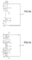
- the figure 5a has a slot made near the upper left corner of the sheet 21.
- the slot is a straight line connecting the points A and B, the point A being at a distance p from the upper edge of the sheet and the point B at a distance q of said upper edge of the sheet 21.
- This slot is associated with a "male" cutting pattern (see figure 5b ) made on another sheet, said pattern comprising two cuts i on either side of a central portion CD having a length less than or equal to the distance between the points A and B, the points C and D being situated on a CD line at the same level as the AB line.
- the slot AB may comprise a cut-out i, for example a cut perpendicular to the slot AB (see FIG. figure 6 and / or the "male" cutting pattern may comprise fold lines j, for example a fold line starting from the point C and a fold line starting from the point D (see figure 7 ).
- the cut lines are obtained by printing these cutting lines on each sheet of paper with an absorbent ink, and by exposing each sheet to a beam of a laser emitting at a length wavelength absorbed by the places inked with absorbent ink.
- the chosen laser is of low power, but of sufficient power to obtain a total ablation (according to the cutting lines) or partial (following the fold lines) of the paper.
- the characteristics of this absorbent ink and the laser are available in document [1].
- An embodiment of the present invention also includes a computer-assisted product that can be accommodated on a storage medium and include instructions that can be used to program a computer to perform the method of the present invention.
- This storage medium may include but is not limited any type of disk including floppy disks, optical disks, CD-ROMs, magneto-optical disks, ROMs, RAMs, EPROMs, EEPROMs, flash memories, magnetic or optical cards, or any type of media suitable for storing electronic instructions.
- This invention may also be advantageously implemented using a conventional computer programmed according to the teachings of current specifications, as will be apparent to those skilled in the computer field.
- the appropriate coding of software can readily be prepared by skilled programmers based on the teachings of the present disclosure, as will be apparent to those skilled in the software field.
- the computer program for cutting and printing according to the present invention can be written in a number of programming languages including, but not limited to, C, C ++, Fortran and Basic, as would be apparent to a person of ordinary skill in this field.
- the invention can also be implemented by preparing application-specific integrated circuits or by connecting together an appropriate network of conventional circuit components, as would be apparent to those skilled in the art.
- a document creation software or printer control
- the definition of the position of the cutting patterns on each sheet can be easily achieved by the document creation software or software associated with the printing and cutting device, through knowledge of the pagination of the document, and the thickness of the paper. It will thus be possible to use a computer and software to match the location of the printed content of each sheet (texts, drawings, illustrations, etc.) with the location of the "male” and “female” type cutting patterns and additional folding and / or cutting lines.
- the use of a software makes it easy to use a printing and cutting device such as that described in document [1] which makes it possible to make both the cuts used for the assembly of the sheets. and printing the sheets with one and the same device.
- the software can make it possible to size the margin, that is to say the space between the cutting line and the printed area, correctly according to the result that one wants to obtain.
- the software can give a null value to the margin so that a large photograph can be positioned and printed on two consecutive sheets.
- the "all paper” assembly solution proposed by the invention makes the use of usual fastening means, such as staples or paper clips, useless. Assembled sheets are thus available which can be destroyed by passing through a chipper without having to first remove the fastening means.
Landscapes
- Handling Of Sheets (AREA)
- Perforating, Stamping-Out Or Severing By Means Other Than Cutting (AREA)
- Superconductors And Manufacturing Methods Therefor (AREA)
- Pressure Welding/Diffusion-Bonding (AREA)
- Folding Of Thin Sheet-Like Materials, Special Discharging Devices, And Others (AREA)
- Coupling Device And Connection With Printed Circuit (AREA)
- Sheet Holders (AREA)
- Toys (AREA)
Claims (14)
- Verfahren zum Zusammenfügen von wenigstens zwei Papierblättern bei Nutzung einer peripheren Vorrichtung mit Einrichtungen zum Bedrucken eines Papierblatts, Einrichtungen zum Schneiden des genannten Papierbfatts und Instruktionsempfangseinrichtungen,
dadurch gekennzeichet, dass es die folgenden Schritte umfaßt:- Herstellung - mit Hilfe der Schneideinrichtungen der peripheren Vorrichtung - wenigstens eines sogenannten "femininen" Zuschnittmusters, das die Form eines Schlitzes aufweist, der sich in einem ersten Blatt (1 ; 11 ; 21) an einer bestimmten, in der Nähe eines Rands des genannten Blatts (1 ; 11 ; 21) befindlichen Stelle von einem Punkt A zu einem Punkt B erstreckt,- Herstellung - für jeden gebildeten Schlitz - eines einem Schlitz zugeordneten sogenannten "maskulinen" Zuschnittmusters in einem zweiten Blatt (2 ; 12 ; 22), das einen durch die Punkte C und D begrenzten zentralen Teil umfasst, der sich auf einer Linie befindet, die durch die Punkte A und B des dem genannten "maskulinen" Muster zugeordneten Schlitzes verläuft, sowie zwei Schnitte (i) beiderseits dieses zentralen Teils, wobei der erste Schnitt von dem Punkt C ausgeht und bis zu einem Rand des zweiten Blattes (2 ; 12 ; 22) verläuft, der zweite Schnitt von dem Punkt D ausgeht und bis zu einem Rand des zweiten Blattes (2 ; 12 ; 22) verläuft, der zentrale Teil eine Länge kleiner oder gleich der die Punkte A und B des zugeordneten Schlitzes trennenden Länge hat und die Schlitze mit Schneideinrichtungen der peripheren Vorrichtung realisiert werden,- Herstellung - wenn es mehr als zwei Blätter gibt - in jedem der restlichen Blätter wenigstens eines Musters des "femininen" Typs oder wenigstens eines Musters des "maskulinen" Typs gemäß dem zugeordneten Herstellungsschritt, wobei die genannten restlichen Blätter alle dasselbe Muster haben,- manuelles Zusammenfügen jedes der Blätter desselben Musters mit dem Blatt eines anderen Musters durch Einfügen des "maskulinen" Musters in das "feminine" Muster. - Zusammenfügungsverfahren nach dem vorangehenden Anspruch, dadurch gekennzeichnet, dass es außerdem einen Schritt zur Herstellung wenigstens einer Faltungslinie (j) mit Hilfe der Schneideinrichtungen der peripheren Vorrichtung umfasst, die von dem Punkt C und/oder dem Punkt D ausgeht und bis zum Rand des zweiten Blatts (2 ; 12 ; 22) geht, um das Einrühren des gemäß der Faltungslinie oder -linien (j) gefalteten "maskulinen" Zuschnitts in den "femininen" Zuschnitt zu erleichtern.
- Zusammenfügungsverfahren nach dem vorangehenden Anspruch, dadurch gekennzeichnet, dass die von dem Punkt C (dem Punkt D) ausgehende Faltungslinie (j) mit dem von dem Punkt C (dem Punkt D) ausgehenden Schnitt einen stumpfen Winkel θ bildet, wobei der genannte stumpfe Winkel zwischen 90° und 135° enthalten ist.
- Zusammenfügungsverfahren nach Anspruch 2 oder 3, dadurch gekennzeichnet, dass das "maskuline" Zuschnittmuster zwei
Faltungslinien (j) umfasst: eine von dem Punkt C ausgehende Faltungslinie und eine von dem Punkt D ausgehende Faltungslinie. - Zusammenfügungsverfahren nach einem der vorangehenden Ansprüche, dadurch gekennzeichnet, dass es außerdem einen Schritt zur Herstellung wenigstens eines Schnitts (i) umfasst, der von einem sich zwischen den Punkten A und B befindlichen Punkt des schlitzförmigen femininen Musters ausgehend den Blattrand durchschneidet.
- Zusammenfügungsverfahren nach dem vorangehenden Anspruch, dadurch gekennzeichnet, dass der Schlitz einen einzigen Schnitt mit gleichem Abstand vom Punkt A und vom Punkt B umfasst.
- Zusammenfügungsverfahren nach Anspruch 5, dadurch gekennzeichnet, dass der Schlitz zwei Schnitte umfasst, einen von dem auf dem Schlitz befindlichen Punkt A' ausgehenden ersten Schnitt und einem von dem auf dem Schlitz befindlichen Punkt B' ausgehenden zweiten Schnitt, wobei die Abstände AA' und BB' gleich sind.
- Zusammenfügungsverfahren nach einem der vorangehenden Ansprüche, dadurch gekennzeichnet, dass die Marge bzw. Randbreite zwischen der Schnittlinie (i) und einer bedruckten Zone für zwei aufeinanderfolgende Blätter kleiner oder gleich der Dicke eines der beiden Blätter ist.
- Zusammenfügungsverfahren nach einem der vorangehenden Ansprüche, dadurch gekennzeichnet, dass die bestimmte Stelle wenigstens eines "femininen" Zuschnittmusters sich ebenfalls in der Nähe einer Ecke des Blatts (1 ; 11 ; 21) befindet.
- Zusammenfügungsverfahren nach einem der vorangehenden Ansprüche, dadurch gekennzeichnet, dass der Schlitz des "femininen" Zuschnittmusters eine vom Punkt A zum Punkt B gehende gerade Linie ist.
- Zusammenfügungsverfahren nach einem der vorangehenden Ansprüche, dadurch gekennzeichnet, dass der Schnitt oder die Schnitte (i) in jedem Blatt durch das Aufdrucken des Zuschnittmusters auf das fragliche Blatt mit einer tief in das genannte Papierblatt eindringenden absorbierenden Tinte realisiert werden, wobei man das genannte Blatt dann dem Strahl eines Lasers mit schwacher Leistung aussetzt, der entsprechend empfangener Instruktionen mit einer von der absorbierenden Tinte absorbierten Wellenlänge emittiert, wobei die Leistung des Lasers ausreicht, um das Papierblatt an den tintenbedruckten Stellen zu durchschneiden.
- Zusammenfügungsverfahren nach einem der vorangehenden Ansprüche, dadurch gekennzeichnet, dass die wenigstens eine Faltungslinie (j) eines Blatts durch das Aufdrucken des Zuschnittmusters auf das fragliche Blatt mit einer tief in das genannte Papierblatt eindringenden absorbierenden Tinte realisiert wird, wobei man das genannte Blatt dann dem Strahl eines Lasers mit schwacher Leistung aussetzt, der entsprechend empfangener Instruktionen mit einer die absorbierende Tinte absorbierenden Wellenlänge emittiert, wobei die Leistung des Lasers ausreicht, eine partielle Ablation des Papiers an den genannten mit absorbierender Tinte bedruckten Stellen zu erhalten.
- Zusammenfügungsverfahren nach Anspruch 11 oder 12, dadurch gekennzeichnet, dass der Laser einer der Laser einer mehrere Laser umfassenden Lasermatrix ist, wobei jeder Laser individuell gesteuert wird.
- Zusammenfügungsverfahren nach einem der vorangehenden Ansprüche, dadurch gekennzeichnet, dass wenigstens eines der zusammenzufügenden Blätter mit Hilfe der Druckeinrichtungen der Vorrichtung bedruckt wird.
Applications Claiming Priority (2)
| Application Number | Priority Date | Filing Date | Title |
|---|---|---|---|
| FR0553081A FR2891767B1 (fr) | 2005-10-11 | 2005-10-11 | Procede pour assembler plusieurs pages entre elles |
| PCT/EP2006/067262 WO2007042527A1 (fr) | 2005-10-11 | 2006-10-11 | Procede pour assembler plusieurs pages entre elles. |
Publications (2)
| Publication Number | Publication Date |
|---|---|
| EP1943106A1 EP1943106A1 (de) | 2008-07-16 |
| EP1943106B1 true EP1943106B1 (de) | 2010-02-17 |
Family
ID=36699206
Family Applications (1)
| Application Number | Title | Priority Date | Filing Date |
|---|---|---|---|
| EP06807139A Not-in-force EP1943106B1 (de) | 2005-10-11 | 2006-10-11 | Verfahren zum zusammenfügen mehrerer seiten |
Country Status (8)
| Country | Link |
|---|---|
| US (1) | US20070082560A1 (de) |
| EP (1) | EP1943106B1 (de) |
| JP (1) | JP2009511301A (de) |
| AT (1) | ATE457879T1 (de) |
| DE (1) | DE602006012348D1 (de) |
| ES (1) | ES2341184T3 (de) |
| FR (1) | FR2891767B1 (de) |
| WO (1) | WO2007042527A1 (de) |
Families Citing this family (4)
| Publication number | Priority date | Publication date | Assignee | Title |
|---|---|---|---|---|
| US8155576B2 (en) * | 2007-05-30 | 2012-04-10 | Canon Kabushiki Kaisha | Sheet processing apparatus and image forming apparatus |
| JP2013198932A (ja) * | 2012-03-26 | 2013-10-03 | Dainippon Printing Co Ltd | レーザ加工データ分配システムおよびレーザ加工装置 |
| JP2014026186A (ja) * | 2012-07-30 | 2014-02-06 | Miyakoshi Printing Machinery Co Ltd | ラベル用紙のハーフカット型抜き加工方法 |
| JP7043388B2 (ja) * | 2018-11-30 | 2022-03-29 | ローランドディー.ジー.株式会社 | カッティングヘッド付きプリンタ |
Family Cites Families (11)
| Publication number | Priority date | Publication date | Assignee | Title |
|---|---|---|---|---|
| US727283A (en) * | 1903-02-10 | 1903-05-05 | Parker B Cady | Flexible photographic film. |
| US2598379A (en) * | 1951-04-04 | 1952-05-27 | Mcbee Co | Spread sheet |
| DE7934954U1 (de) * | 1979-12-12 | 1980-03-27 | Schneider, Friedrich, 8032 Graefelfing | |
| JPS60162062A (ja) * | 1984-02-02 | 1985-08-23 | Mitsubishi Motors Corp | 内燃機関の制御装置 |
| WO1992012862A1 (en) * | 1991-01-25 | 1992-08-06 | Andyval Inc. | A device for attaching sheets together |
| DE29712362U1 (de) * | 1997-07-12 | 1997-09-11 | Gaab, Alexander, 97900 Külsheim | Zerlegbarer Steckhalter für Papiere, Postkarten und Visitenkarten |
| US6715749B2 (en) * | 2002-08-30 | 2004-04-06 | Hewlett-Packard Development Company, L.P. | Booklet maker and method of manufacturing a booklet maker |
| WO2004024466A1 (en) * | 2002-09-10 | 2004-03-25 | Olof Karlsson | Device for joining and sealing of documents |
| US6926400B2 (en) * | 2002-10-31 | 2005-08-09 | Hewlett-Packard Development Company, L.P. | Media incising printer |
| FR2850308B1 (fr) | 2003-01-28 | 2005-03-04 | Commissariat Energie Atomique | Peripherique permettant l'impression et la decoupe de feuilles de papier a l'aide d'une source laser de faible puissance |
| JP4552443B2 (ja) * | 2004-01-27 | 2010-09-29 | 富士ゼロックス株式会社 | 面発光型半導体レーザアレイ |
-
2005
- 2005-10-11 FR FR0553081A patent/FR2891767B1/fr not_active Expired - Fee Related
- 2005-11-04 US US11/266,335 patent/US20070082560A1/en not_active Abandoned
-
2006
- 2006-10-11 WO PCT/EP2006/067262 patent/WO2007042527A1/fr not_active Ceased
- 2006-10-11 ES ES06807139T patent/ES2341184T3/es active Active
- 2006-10-11 DE DE602006012348T patent/DE602006012348D1/de active Active
- 2006-10-11 AT AT06807139T patent/ATE457879T1/de not_active IP Right Cessation
- 2006-10-11 JP JP2008535018A patent/JP2009511301A/ja active Pending
- 2006-10-11 EP EP06807139A patent/EP1943106B1/de not_active Not-in-force
Also Published As
| Publication number | Publication date |
|---|---|
| ES2341184T3 (es) | 2010-06-16 |
| JP2009511301A (ja) | 2009-03-19 |
| ATE457879T1 (de) | 2010-03-15 |
| FR2891767A1 (fr) | 2007-04-13 |
| EP1943106A1 (de) | 2008-07-16 |
| WO2007042527A1 (fr) | 2007-04-19 |
| US20070082560A1 (en) | 2007-04-12 |
| DE602006012348D1 (de) | 2010-04-01 |
| FR2891767B1 (fr) | 2007-11-30 |
Similar Documents
| Publication | Publication Date | Title |
|---|---|---|
| EP1587683B1 (de) | Zum drucken und schneiden von papierbögen unter verwendung einer laserquelle mit niedriger leistung verwendbares peripheriegerät | |
| EP1291195B1 (de) | Bedienelement für bedruckte Gegenstände | |
| EP1943106B1 (de) | Verfahren zum zusammenfügen mehrerer seiten | |
| FR2705644A1 (fr) | Carte de souhaits. | |
| EP1074397A1 (de) | Automatisches System zur Vorbereitung auf Anfrage eines Hefts | |
| CA2939663C (fr) | Document pourvu d'un dispositif de securisation d'une information confidentielle mentionnee dans le document et procede de mise en oeuvre d'un tel dispositif | |
| EP2177249A1 (de) | Puzzlebuch für Kinder | |
| EP0509884B1 (de) | Endlossatz von geschlossenen Briefumschlägen mit jeweils einer Zusatztasche | |
| EP3797037B1 (de) | Verfahren zur behandlung eines anpassbaren blattes für ein sicherheitsheft | |
| FR3011358A1 (fr) | Procede pour l'impression, notamment en petite serie. | |
| EP0625432B1 (de) | Unterschriften- oder Sortiermappe mit mehreren Haltestreifen | |
| WO2025171878A1 (fr) | Procede de conception numerique et de fabrication d'elements pour la fabrication d'un objet en trois dimensions, l'installation permettant sa mise en œuvre, et elements pour la fabrication d'objets en trois dimensions | |
| EP2412256B1 (de) | Zigarettenpapierheftchen, die mit einer perfektionierten Markierung versehen sind | |
| FR2696264A1 (fr) | Couverture, notamment pour trieur, classeur ou parapheur et procédé de fabrication et de fixation d'une telle couverture. | |
| BE504424A (de) | ||
| EP2767409B1 (de) | Verfahren zur Erstellung von Mehrfachmitteilungen | |
| FR3145503A1 (fr) | Procédé de conception et de fabrication numérique d’éléments pour la fabrication d’un objet en trois dimensions, l’installation permettant sa mise en œuvre, et éléments pour la fabrication d’objets en trois dimensions. | |
| JP3154873U (ja) | Cdジャケット | |
| BE470860A (de) | ||
| FR3125982A3 (fr) | Parapheur à onglets de rétention. | |
| FR2680724A1 (fr) | Parapheur ou trieur muni de moyens de retention. | |
| EP1006004A1 (de) | Unterschriften- oder Sortiermappe mit einem einschiebaren Merkzeichnensystem | |
| FR2692522A1 (fr) | Imprimé pour des formulaires. | |
| FR2925941A1 (fr) | Systeme d'assemblage de feuille(s) et/ou de produit(s) plan(s) analogue(s) permettant une desunion | |
| BE407689A (de) |
Legal Events
| Date | Code | Title | Description |
|---|---|---|---|
| PUAI | Public reference made under article 153(3) epc to a published international application that has entered the european phase |
Free format text: ORIGINAL CODE: 0009012 |
|
| 17P | Request for examination filed |
Effective date: 20080326 |
|
| AK | Designated contracting states |
Kind code of ref document: A1 Designated state(s): AT BE BG CH CY CZ DE DK EE ES FI FR GB GR HU IE IS IT LI LT LU LV MC NL PL PT RO SE SI SK TR |
|
| GRAP | Despatch of communication of intention to grant a patent |
Free format text: ORIGINAL CODE: EPIDOSNIGR1 |
|
| GRAS | Grant fee paid |
Free format text: ORIGINAL CODE: EPIDOSNIGR3 |
|
| GRAA | (expected) grant |
Free format text: ORIGINAL CODE: 0009210 |
|
| AK | Designated contracting states |
Kind code of ref document: B1 Designated state(s): AT BE BG CH CY CZ DE DK EE ES FI FR GB GR HU IE IS IT LI LT LU LV MC NL PL PT RO SE SI SK TR |
|
| REG | Reference to a national code |
Ref country code: GB Ref legal event code: FG4D Free format text: NOT ENGLISH |
|
| REG | Reference to a national code |
Ref country code: CH Ref legal event code: EP |
|
| REG | Reference to a national code |
Ref country code: IE Ref legal event code: FG4D Free format text: LANGUAGE OF EP DOCUMENT: FRENCH |
|
| REF | Corresponds to: |
Ref document number: 602006012348 Country of ref document: DE Date of ref document: 20100401 Kind code of ref document: P |
|
| REG | Reference to a national code |
Ref country code: NL Ref legal event code: T3 |
|
| REG | Reference to a national code |
Ref country code: ES Ref legal event code: FG2A Ref document number: 2341184 Country of ref document: ES Kind code of ref document: T3 |
|
| LTIE | Lt: invalidation of european patent or patent extension |
Effective date: 20100217 |
|
| PG25 | Lapsed in a contracting state [announced via postgrant information from national office to epo] |
Ref country code: IS Free format text: LAPSE BECAUSE OF FAILURE TO SUBMIT A TRANSLATION OF THE DESCRIPTION OR TO PAY THE FEE WITHIN THE PRESCRIBED TIME-LIMIT Effective date: 20100617 Ref country code: PT Free format text: LAPSE BECAUSE OF FAILURE TO SUBMIT A TRANSLATION OF THE DESCRIPTION OR TO PAY THE FEE WITHIN THE PRESCRIBED TIME-LIMIT Effective date: 20100617 Ref country code: LT Free format text: LAPSE BECAUSE OF FAILURE TO SUBMIT A TRANSLATION OF THE DESCRIPTION OR TO PAY THE FEE WITHIN THE PRESCRIBED TIME-LIMIT Effective date: 20100217 |
|
| PG25 | Lapsed in a contracting state [announced via postgrant information from national office to epo] |
Ref country code: FI Free format text: LAPSE BECAUSE OF FAILURE TO SUBMIT A TRANSLATION OF THE DESCRIPTION OR TO PAY THE FEE WITHIN THE PRESCRIBED TIME-LIMIT Effective date: 20100217 Ref country code: SI Free format text: LAPSE BECAUSE OF FAILURE TO SUBMIT A TRANSLATION OF THE DESCRIPTION OR TO PAY THE FEE WITHIN THE PRESCRIBED TIME-LIMIT Effective date: 20100217 Ref country code: PL Free format text: LAPSE BECAUSE OF FAILURE TO SUBMIT A TRANSLATION OF THE DESCRIPTION OR TO PAY THE FEE WITHIN THE PRESCRIBED TIME-LIMIT Effective date: 20100217 Ref country code: LV Free format text: LAPSE BECAUSE OF FAILURE TO SUBMIT A TRANSLATION OF THE DESCRIPTION OR TO PAY THE FEE WITHIN THE PRESCRIBED TIME-LIMIT Effective date: 20100217 Ref country code: AT Free format text: LAPSE BECAUSE OF FAILURE TO SUBMIT A TRANSLATION OF THE DESCRIPTION OR TO PAY THE FEE WITHIN THE PRESCRIBED TIME-LIMIT Effective date: 20100217 |
|
| REG | Reference to a national code |
Ref country code: IE Ref legal event code: FD4D |
|
| PG25 | Lapsed in a contracting state [announced via postgrant information from national office to epo] |
Ref country code: RO Free format text: LAPSE BECAUSE OF FAILURE TO SUBMIT A TRANSLATION OF THE DESCRIPTION OR TO PAY THE FEE WITHIN THE PRESCRIBED TIME-LIMIT Effective date: 20100217 Ref country code: CY Free format text: LAPSE BECAUSE OF FAILURE TO SUBMIT A TRANSLATION OF THE DESCRIPTION OR TO PAY THE FEE WITHIN THE PRESCRIBED TIME-LIMIT Effective date: 20100217 Ref country code: GR Free format text: LAPSE BECAUSE OF FAILURE TO SUBMIT A TRANSLATION OF THE DESCRIPTION OR TO PAY THE FEE WITHIN THE PRESCRIBED TIME-LIMIT Effective date: 20100518 Ref country code: EE Free format text: LAPSE BECAUSE OF FAILURE TO SUBMIT A TRANSLATION OF THE DESCRIPTION OR TO PAY THE FEE WITHIN THE PRESCRIBED TIME-LIMIT Effective date: 20100217 Ref country code: IE Free format text: LAPSE BECAUSE OF FAILURE TO SUBMIT A TRANSLATION OF THE DESCRIPTION OR TO PAY THE FEE WITHIN THE PRESCRIBED TIME-LIMIT Effective date: 20100217 Ref country code: SE Free format text: LAPSE BECAUSE OF FAILURE TO SUBMIT A TRANSLATION OF THE DESCRIPTION OR TO PAY THE FEE WITHIN THE PRESCRIBED TIME-LIMIT Effective date: 20100217 |
|
| PG25 | Lapsed in a contracting state [announced via postgrant information from national office to epo] |
Ref country code: SK Free format text: LAPSE BECAUSE OF FAILURE TO SUBMIT A TRANSLATION OF THE DESCRIPTION OR TO PAY THE FEE WITHIN THE PRESCRIBED TIME-LIMIT Effective date: 20100217 Ref country code: CZ Free format text: LAPSE BECAUSE OF FAILURE TO SUBMIT A TRANSLATION OF THE DESCRIPTION OR TO PAY THE FEE WITHIN THE PRESCRIBED TIME-LIMIT Effective date: 20100217 Ref country code: BG Free format text: LAPSE BECAUSE OF FAILURE TO SUBMIT A TRANSLATION OF THE DESCRIPTION OR TO PAY THE FEE WITHIN THE PRESCRIBED TIME-LIMIT Effective date: 20100517 |
|
| PLBE | No opposition filed within time limit |
Free format text: ORIGINAL CODE: 0009261 |
|
| STAA | Information on the status of an ep patent application or granted ep patent |
Free format text: STATUS: NO OPPOSITION FILED WITHIN TIME LIMIT |
|
| 26N | No opposition filed |
Effective date: 20101118 |
|
| PG25 | Lapsed in a contracting state [announced via postgrant information from national office to epo] |
Ref country code: DK Free format text: LAPSE BECAUSE OF FAILURE TO SUBMIT A TRANSLATION OF THE DESCRIPTION OR TO PAY THE FEE WITHIN THE PRESCRIBED TIME-LIMIT Effective date: 20100217 |
|
| PG25 | Lapsed in a contracting state [announced via postgrant information from national office to epo] |
Ref country code: IT Free format text: LAPSE BECAUSE OF FAILURE TO SUBMIT A TRANSLATION OF THE DESCRIPTION OR TO PAY THE FEE WITHIN THE PRESCRIBED TIME-LIMIT Effective date: 20100217 |
|
| PG25 | Lapsed in a contracting state [announced via postgrant information from national office to epo] |
Ref country code: MC Free format text: LAPSE BECAUSE OF NON-PAYMENT OF DUE FEES Effective date: 20101031 |
|
| PG25 | Lapsed in a contracting state [announced via postgrant information from national office to epo] |
Ref country code: HU Free format text: LAPSE BECAUSE OF FAILURE TO SUBMIT A TRANSLATION OF THE DESCRIPTION OR TO PAY THE FEE WITHIN THE PRESCRIBED TIME-LIMIT Effective date: 20100818 Ref country code: LU Free format text: LAPSE BECAUSE OF NON-PAYMENT OF DUE FEES Effective date: 20101011 |
|
| PG25 | Lapsed in a contracting state [announced via postgrant information from national office to epo] |
Ref country code: TR Free format text: LAPSE BECAUSE OF FAILURE TO SUBMIT A TRANSLATION OF THE DESCRIPTION OR TO PAY THE FEE WITHIN THE PRESCRIBED TIME-LIMIT Effective date: 20100217 |
|
| REG | Reference to a national code |
Ref country code: FR Ref legal event code: PLFP Year of fee payment: 10 |
|
| PGFP | Annual fee paid to national office [announced via postgrant information from national office to epo] |
Ref country code: GB Payment date: 20151019 Year of fee payment: 10 Ref country code: DE Payment date: 20151014 Year of fee payment: 10 Ref country code: CH Payment date: 20151007 Year of fee payment: 10 |
|
| PGFP | Annual fee paid to national office [announced via postgrant information from national office to epo] |
Ref country code: NL Payment date: 20150921 Year of fee payment: 10 Ref country code: ES Payment date: 20151026 Year of fee payment: 10 Ref country code: FR Payment date: 20151102 Year of fee payment: 10 Ref country code: BE Payment date: 20151029 Year of fee payment: 10 |
|
| PG25 | Lapsed in a contracting state [announced via postgrant information from national office to epo] |
Ref country code: BE Free format text: LAPSE BECAUSE OF NON-PAYMENT OF DUE FEES Effective date: 20161031 |
|
| REG | Reference to a national code |
Ref country code: DE Ref legal event code: R119 Ref document number: 602006012348 Country of ref document: DE |
|
| REG | Reference to a national code |
Ref country code: CH Ref legal event code: PL |
|
| REG | Reference to a national code |
Ref country code: NL Ref legal event code: MM Effective date: 20161101 |
|
| GBPC | Gb: european patent ceased through non-payment of renewal fee |
Effective date: 20161011 |
|
| REG | Reference to a national code |
Ref country code: FR Ref legal event code: ST Effective date: 20170630 |
|
| PG25 | Lapsed in a contracting state [announced via postgrant information from national office to epo] |
Ref country code: LI Free format text: LAPSE BECAUSE OF NON-PAYMENT OF DUE FEES Effective date: 20161031 Ref country code: FR Free format text: LAPSE BECAUSE OF NON-PAYMENT OF DUE FEES Effective date: 20161102 Ref country code: CH Free format text: LAPSE BECAUSE OF NON-PAYMENT OF DUE FEES Effective date: 20161031 Ref country code: GB Free format text: LAPSE BECAUSE OF NON-PAYMENT OF DUE FEES Effective date: 20161011 Ref country code: DE Free format text: LAPSE BECAUSE OF NON-PAYMENT OF DUE FEES Effective date: 20170503 |
|
| PG25 | Lapsed in a contracting state [announced via postgrant information from national office to epo] |
Ref country code: NL Free format text: LAPSE BECAUSE OF NON-PAYMENT OF DUE FEES Effective date: 20161101 |
|
| REG | Reference to a national code |
Ref country code: BE Ref legal event code: MM Effective date: 20161031 |
|
| PG25 | Lapsed in a contracting state [announced via postgrant information from national office to epo] |
Ref country code: ES Free format text: LAPSE BECAUSE OF NON-PAYMENT OF DUE FEES Effective date: 20161012 |
|
| REG | Reference to a national code |
Ref country code: ES Ref legal event code: FD2A Effective date: 20181128 |