EP1943878B1 - Kochfeld und verfahren zum betreiben eines kochfelds - Google Patents
Kochfeld und verfahren zum betreiben eines kochfelds Download PDFInfo
- Publication number
- EP1943878B1 EP1943878B1 EP06807106A EP06807106A EP1943878B1 EP 1943878 B1 EP1943878 B1 EP 1943878B1 EP 06807106 A EP06807106 A EP 06807106A EP 06807106 A EP06807106 A EP 06807106A EP 1943878 B1 EP1943878 B1 EP 1943878B1
- Authority
- EP
- European Patent Office
- Prior art keywords
- heating
- switching
- heating zone
- cooking hob
- operating mode
- Prior art date
- Legal status (The legal status is an assumption and is not a legal conclusion. Google has not performed a legal analysis and makes no representation as to the accuracy of the status listed.)
- Active
Links
Images


Classifications
-
- H—ELECTRICITY
- H05—ELECTRIC TECHNIQUES NOT OTHERWISE PROVIDED FOR
- H05B—ELECTRIC HEATING; ELECTRIC LIGHT SOURCES NOT OTHERWISE PROVIDED FOR; CIRCUIT ARRANGEMENTS FOR ELECTRIC LIGHT SOURCES, IN GENERAL
- H05B6/00—Heating by electric, magnetic or electromagnetic fields
- H05B6/02—Induction heating
- H05B6/04—Sources of current
-
- H—ELECTRICITY
- H05—ELECTRIC TECHNIQUES NOT OTHERWISE PROVIDED FOR
- H05B—ELECTRIC HEATING; ELECTRIC LIGHT SOURCES NOT OTHERWISE PROVIDED FOR; CIRCUIT ARRANGEMENTS FOR ELECTRIC LIGHT SOURCES, IN GENERAL
- H05B6/00—Heating by electric, magnetic or electromagnetic fields
- H05B6/02—Induction heating
- H05B6/06—Control, e.g. of temperature, of power
- H05B6/062—Control, e.g. of temperature, of power for cooking plates or the like
- H05B6/065—Control, e.g. of temperature, of power for cooking plates or the like using coordinated control of multiple induction coils
-
- H—ELECTRICITY
- H05—ELECTRIC TECHNIQUES NOT OTHERWISE PROVIDED FOR
- H05B—ELECTRIC HEATING; ELECTRIC LIGHT SOURCES NOT OTHERWISE PROVIDED FOR; CIRCUIT ARRANGEMENTS FOR ELECTRIC LIGHT SOURCES, IN GENERAL
- H05B6/00—Heating by electric, magnetic or electromagnetic fields
- H05B6/02—Induction heating
- H05B6/10—Induction heating apparatus, other than furnaces, for specific applications
- H05B6/12—Cooking devices
- H05B6/1209—Cooking devices induction cooking plates or the like and devices to be used in combination with them
- H05B6/1245—Cooking devices induction cooking plates or the like and devices to be used in combination with them with special coil arrangements
- H05B6/1272—Cooking devices induction cooking plates or the like and devices to be used in combination with them with special coil arrangements with more than one coil or coil segment per heating zone
-
- Y—GENERAL TAGGING OF NEW TECHNOLOGICAL DEVELOPMENTS; GENERAL TAGGING OF CROSS-SECTIONAL TECHNOLOGIES SPANNING OVER SEVERAL SECTIONS OF THE IPC; TECHNICAL SUBJECTS COVERED BY FORMER USPC CROSS-REFERENCE ART COLLECTIONS [XRACs] AND DIGESTS
- Y02—TECHNOLOGIES OR APPLICATIONS FOR MITIGATION OR ADAPTATION AGAINST CLIMATE CHANGE
- Y02B—CLIMATE CHANGE MITIGATION TECHNOLOGIES RELATED TO BUILDINGS, e.g. HOUSING, HOUSE APPLIANCES OR RELATED END-USER APPLICATIONS
- Y02B40/00—Technologies aiming at improving the efficiency of home appliances, e.g. induction cooking or efficient technologies for refrigerators, freezers or dish washers
Definitions
- the invention relates to a hob according to the preamble of claim 1 and to a method for operating a hob according to the preamble of claim 12.
- An induction hob with at least one first heating zone which has two independently heatable heating elements, which are operated in a normal operating mode via a first switching device with a first power supply device.
- In the normal operating mode can be operated depending on a size of Gargut mattersers or pot, which is arranged on the heating zone, both heating elements or only one heating element of the heating zone.
- induction hobs with further heating zones for heating further food containers or pots are known from the prior art, which are operated in the normal operating mode via a second switching device with a second power supply device.
- the object of the invention is in particular to provide a generic hob with a special mode in which a heating power of the first heating zone above a maximum power of the first power supply device can be increased and in the normal operating mode, the first heating zone with both heating elements and the other heating zone simultaneously can be operated.
- the invention is based on a hob, in particular an induction hob, with at least one first heating zone having at least two independently heatable heating elements, which are operated in a normal operating mode via a first switching device with a first power supply device, and with at least one other Heating zone, which is operated in the normal operating mode via a second switching device with a second power supply device.
- the cooktop comprises a switching element for establishing a power supply connection between the second power supply device and one of the heating elements of the first heating zone, the power supply connection being produced in a special operating mode for increasing a heating power of the first heating zone.
- the second power supply device is used to supply the first heating zone only when the special operating mode is active or only when a heating power exceeding the maximum power of the first power supply device is actually requested. It can be achieved, in particular, that the second power supply device is always available for operating the further heating zone in the normal mode, even if both heating elements of the first heating zone are in operation.
- the size and shape of the heating zone can be varied by the switching on and off of heating elements.
- the idea of the invention can be used profitably mainly in the field of induction hobs because of the high-frequency technology used there, in principle also a use in connection with hobs with ohmic heating elements is conceivable.
- an intermodulation hum can be avoided when operating a plurality of heating elements with different frequencies.
- the intermodulation buzzing can be avoided particularly reliably if the hob comprises a synchronization line for synchronizing the power supply devices.
- a frequency generator of a first power supply device as a master and a frequency generator of the second power supply device can be used as a slave.
- the frequency encoders of the power supply devices can be designed to be particularly space-saving and cost-effective as application-specific integrated circuits (ASICs), which each control an inverter of the power supply device.
- ASICs application-specific integrated circuits
- the application specific integrated circuits can in turn be operated by a low-frequency switching microcontroller, which may be arranged together with the ASIC and the inverter on a common circuit board which carries the switching device.
- a low-frequency switching microcontroller which may be arranged together with the ASIC and the inverter on a common circuit board which carries the switching device.
- the two switching devices are carried by a common circuit board.
- a comfortable, short-term increase in heating power can be achieved by a switching means for manually activating the special operating mode. Overheating of the hob can be avoided if the special operating mode automatically deactivates after the expiration of a preset time.
- the special operating mode can thus be regarded as a short-term heating power boost. Further embodiments of the invention are conceivable in which the special operating mode is automatically deactivated when a temperature threshold is reached.
- An overload of the second power supply device can be avoided if the further heating zone is deactivated in the special operating mode. This can be achieved either by deactivating the second heating zone for the duration of operation in the special operating mode or by blocking the activation of the special operating mode whenever the further heating zone is active and conversely the further heating zone during operation in the special operating mode can not be switched on.
- the hob comprises a connection line for connecting the second power supply device to one of the heating elements of the first heating zone, crosstalk of the frequencies of the two power supply devices can be at least reduced by a remote arrangement thereof.
- a disturbance due to a disturbance frequency, as produced by a non-linear superimposition of the conversion frequencies of the two switching devices, can be controlled if one of the switching devices is intended to limit a difference frequency between a conversion frequency of the first switching device and a conversion frequency of the second switching device.
- An audible acoustic disturbance can be completely avoided if the switching device is intended to determine the difference frequency to lie outside an audible frequency band.
- the hob comprises a switching device for changing the connections between the power supply devices and the heating zones for switching between the normal operating mode and the special operating mode
- the power supply devices from conventional cooking hobs can be used largely without change in a hob according to the invention. A number of additional cabling can be reduced.
- Additional lines carrying a working current can be avoided when a first switch for disconnecting a first heating element of the first heating zone from the first power supply device is arranged in the first switching device.
- the invention relates to a method for operating a hob, in particular an induction hob, having at least a first heating zone having at least two independently heatable heating elements, wherein in a normal operating mode, the two heating elements are operated via a first switching device with a first power supply device and another heating zone is operated via a second switching device with a second power supply device.
- a switching element for establishing a power supply connection between the second power supply device and one of the heating elements of the first heating zone is actuated for switching on and off a special operating mode for increasing a heating power of the first heating zone.
- a generic hob can be operated in a special operating mode in which a heating power of the first heating zone can be increased above a maximum power of the first power supply device.
- both heating elements of the first heating zone and the other heating zone can be operated simultaneously in the normal operating mode.
- FIG. 1 shows an induction hob with a total of three heating zones 10, 12, 14.
- a first heating zone 10 has two independently operable heating elements 16, 18 in the form of concentric rings, which are operated in a normal operating mode via a first switching device 20 with a first power supply device 26.
- the power supply device 26 has two outputs 40, 42.
- the heating elements 16, 18 are formed as induction coils and provided to transmit electrical energy to a resonator circuit in a cooking utensil or pot, not shown here, on the Induction hob can be arranged.
- the induction hob also includes a Kochtopferkennungungssystem that detects about the load or a complex-valued impedance of the heating elements 16, 18, whether a cooking product is placed on the induction hob and what size of Gargut capableer has. If the cooking utensil container is significantly larger than the inner heating element 16, the first switching device 20 for heating the cooking utensil next to the inner heating element 16 also switches on the first, outer heating element 18, which surrounds the inner heating element 16 in an annular manner.
- the two further heating zones 12, 14 are operated in the normal operating mode via a second switching device 22 with a second power supply device 28, which also has two outputs 44, 46.
- a power supply connection between the second power supply device 28 and the outer, annular heating element 18 of the first heating zone 10 can be produced.
- the input unit 47 includes a special key that forms a switching means 34 for manually activating the special mode of operation. After the expiration of a preset time, the special operation mode ends automatically and without further operator intervention.
- the two further heating zones 12, 14 are simultaneously deactivated.
- the high-frequency AC voltage generated by the corresponding output 44 of the second power supply device 28 is given by the switching or electronic switching of the integrated into the second switching device 22 switching element 32 to a connecting line 38.
- the connection line 38 is provided for connecting the second power supply device 28 to the outer heating element 18 of the first heating zone 10.
- the connecting line 38 opens into a further switching device 24 for changing the links between the power supply devices 26, 28 and the heating zones 10, 12, 14.
- the further switching device 24 changes these links for switching between the normal operating mode and the special operating mode and also includes the first switching element 30th
- the switching of a first switching element 30 of the further switching device 24 interrupts a connection between the output 42 of the first power supply device 26 and the outer heating element 18 of the first heating zone 10 and at the same time a connection between the outer heating element 18 and the connecting line 38 or the output 44 of the second power supply device 28.
- the switching elements 30, 32 are switched simultaneously by a central control unit of the induction hob.
- the further switching device 24 and thus also the first switching element 30 are integrated in the first switching device 20 or arranged directly next to the first switching device 20.
- the first switching element 30 therefore serves to connect the outer heating element 18 of the first heating zone 10 to the second power supply device 28 and is arranged in the second switching device 22 or integrated into the second switching device 22.
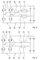
- FIG. 2 shows the right switching device 22 from FIG. 1 in a more detailed presentation.
- the switching device 22 comprises, in addition to an inverter circuit 58 for the independent power supply of the heating zones 12, 14, two switching elements 60, 62 for switching between sub-modes of the normal operating mode, in which either one of the heating zones 12, 14 or both heating zones 12, 14 are operated.
- the inverter circuit 58 comprises a total of four inverter diodes and four capacitors.
- the switching element 32 is integrated in the switching device 22.
- Analog shows FIG. 3 the left switching device 20 from FIG. 1 in a more detailed presentation.
- the switching device 20 comprises, in addition to an inverter circuit 56 for the independent power supply of the heating elements 16, 18 of the heating zone 10, two switching elements 64, 66 for switching between sub-modes of the normal operating mode in which either one of the heating elements 16, 18 or both heating elements 16, 18 of the heating zone 10 operated become.
- FIG. 4 shows the two switching devices 20, 22 and power supply devices 26, 28 in an alternative representation.
- Each of the switching devices 20, 22 comprises a microcontroller 48, 50, which is controlled by signals of the input unit 47.
- the input unit 47 also includes a central control unit for controlling an entire cooking appliance, which in addition to the induction hob also includes an oven not explicitly shown here.
- the microcontroller 48, 50 in turn each control an ASIC 52, 54 (Application Specific Integrated Circuit), which generates the high-frequency signals necessary for generating a high-frequency heating voltage and in the FIGS. 2 and 3 Inverter circuits 56, 58 shown in more detail.
- ASIC 52, 54 Application Specific Integrated Circuit
- the two switching devices 20, 22 are interconnected by a synchronization line 36 for synchronizing the power supply devices 26, 28 in the special mode of operation. If the special operating mode is activated, the ASIC 52 of the first switching device 20 operates as a master and transmits the Umrichtfrequenz U1 and a difference frequency DF to the operating as a slave further switching device 22 and to the corresponding ASIC 52 on. The microcontroller 50 of the further switching device 24 is thus disabled. In particular, a phase control signal can also be transmitted via this synchronization line 36.
- the first switching device 20 is designed so that in the special mode a differential frequency DF between a Umrichtfrequenz U1 of the first switching device 20 and a Umrichtfrequenz U2 of the second switching device 22 always has the value zero and therefore limited is.
- the difference frequency DF is always outside an audible frequency band of about 100 Hz to 10 kHz.
Landscapes
- Physics & Mathematics (AREA)
- Electromagnetism (AREA)
- General Induction Heating (AREA)
- Induction Heating Cooking Devices (AREA)
- Frying-Pans Or Fryers (AREA)
- Electric Stoves And Ranges (AREA)
Description
- Die Erfindung geht aus von einem Kochfeld nach dem Oberbegriff des Anspruchs 1 und von einem Verfahren zum Betreiben eines Kochfelds nach dem Oberbegriff des Anspruchs 12.
- Aus der
WO 2005/043737 A2 ist ein Induktionskochfeld mit wenigstens einer ersten Heizzone bekannt, die zwei unabhängig heizbare Heizelemente aufweist, die in einem Normalbetriebsmodus über eine erste Schaltvorrichtung mit einer ersten Stromversorgungsvorrichtung betrieben werden. Im Normalbetriebsmodus können abhängig von einer Größe eines Gargutbehälters bzw. Topfs, der auf der Heizzone angeordnet ist, beide Heizelemente oder nur ein Heizelement der Heizzone betrieben werden. - Ferner sind aus dem Stand der Technik Induktionskochfelder mit weiteren Heizzonen zum Heizen weiterer Gargutbehälter bzw. Töpfe bekannt, die im Normalbetriebsmodus über eine zweite Schaltvorrichtung mit einer zweiten Stromversorgungsvorrichtung betrieben werden.
- Die Aufgabe der Erfindung besteht insbesondere darin, ein gattungsgemäßes Kochfeld mit einem Sonderbetriebsmodus bereitzustellen, in dem eine Heizleistung der ersten Heizzone über eine maximale Leistung der ersten Stromversorgungsvorrichtung hinaus erhöht werden kann und in dem im Normalbetriebsmodus die erste Heizzone mit beiden Heizelementen und die weitere Heizzone gleichzeitig betrieben werden können.
- Die Aufgabe wird erfindungsgemäß durch die Merkmale des Patentanspruchs 1 gelöst, während vorteilhafte Ausgestaltungen und Weiterbildungen der Erfindung den Unteransprüchen entnommen werden können.
- Die Erfindung geht aus von einem Kochfeld, insbesondere von einem Induktionskochfeld, mit wenigstens einer ersten Heizzone, die zumindest zwei unabhängig heizbare Heizelemente aufweist, die in einem Normalbetriebsmodus über eine erste Schaltvorrichtung mit einer ersten Stromversorgungsvorrichtung betrieben sind, und mit zumindest einer weiteren Heizzone, die im Normalbetriebsmodus über eine zweite Schaltvorrichtung mit einer zweiten Stromversorgungsvorrichtung betrieben ist.
- Es wird vorgeschlagen, dass das Kochfeld ein Schaltelement zum Herstellen einer Stromversorgungsverbindung zwischen der zweiten Stromversorgungsvorrichtung und einem der Heizelemente der ersten Heizzone umfasst, wobei die Stromversorgungsverbindung in einem Sonderbetriebsmodus zur Erhöhung einer Heizleistung der ersten Heizzone hergestellt wird. Dadurch kann erreicht werden, dass die zweite Stromversorgungsvorrichtung nur bei eingeschaltetem Sonderbetriebsmodus bzw. nur genau dann, wenn wirklich eine die maximale Leistung der ersten Stromversorgungsvorrichtung übertreffende Heizleistung angefordert ist, zur Versorgung der ersten Heizzone herangezogen wird. Es kann insbesondere erreicht werden, dass die zweite Stromversorgungsvorrichtung im Normalmodus, und zwar auch dann, wenn beide Heizelemente der ersten Heizzone im Betrieb sind, stets zum Betreiben der weiteren Heizzone zur Verfügung steht.
- Als Heizzone soll in diesem Zusammenhang ein Bereich zum Aufstellen eines einzelnen Gargutbehälters bzw. Topfs bezeichnet werden, wobei die Größe und die Form der Heizzone durch das Zu- und Abschalten von Heizelementen variierbar sein können. Obwohl der Erfindungsgedanke wegen der dort eingesetzten Hochfrequenztechnik hauptsächlich im Bereich von Induktionskochfeldern gewinnbringend einsetzbar ist, ist prinzipiell auch eine Verwendung im Zusammenhang mit Kochfeldern mit ohmschen Heizelementen denkbar.
- Insbesondere dann, wenn die Heizelemente als Induktionsspulen ausgebildet sind, kann ein Intermodulationsbrummen beim Betrieb mehrerer Heizelemente mit unterschiedlichen Frequenzen vermieden werden. Das Intermodulationsbrummen kann besonders sicher vermieden werden, wenn das Kochfeld eine Synchronisationsleitung zum Synchronisieren der Stromversorgungsvorrichtungen umfasst. Zum Synchronisieren der Stromversorgungsvorrichtungen kann ein Frequenzgeber einer ersten Stromversorgungsvorrichtung als Master und ein Frequenzgeber der zweiten Stromversorgungsvorrichtung als Slave eingesetzt werden. Die Frequenzgeber der Stromversorgungsvorrichtungen können besonders raumsparend und kostengünstig als anwendungsspezifische integrierte Schaltungen (ASICs) ausgebildet sein, die jeweils einen Wechselrichter der Stromversorgungsvorrichtung steuern. Die anwendungsspezifischen integrierten Schaltungen können ihrerseits von einem niederfrequent schaltenden Mikrocontroller betrieben sein, der zusammen mit dem ASIC und dem Wechselrichter auf einer gemeinsamen Schaltplatine angeordnet sein kann, die die Schaltvorrichtung trägt. Es sind auch Ausgestaltungen der Erfindung denkbar, in denen die beiden Schaltvorrichtungen von einer gemeinsamen Schaltplatine getragen sind.
- Ein komfortables, kurzfristiges Erhöhen der Heizleistung kann durch ein Schaltmittel zum manuellen Aktivieren des Sonderbetriebsmodus erreicht werden. Ein Überhitzen des Kochfelds kann vermieden werden, wenn sich der Sonderbetriebsmodus nach dem Ablauf einer voreingestellten Zeit automatisch deaktiviert. Der Sonderbetriebsmodus kann dadurch als kurzzeitiger Heizleistungsschub betrachtet werden. Es sind ferner Ausgestaltungen der Erfindung denkbar, in denen der Sonderbetriebsmodus beim Erreichen einer Temperaturschwelle selbsttätig deaktiviert wird.
- Eine Überlastung der zweiten Stromversorgungsvorrichtung kann vermieden werden, wenn die weitere Heizzone im Sonderbetriebsmodus deaktiviert ist. Dies kann entweder dadurch erreicht werden, dass die zweite Heizzone für die Dauer des Betriebs im Sonderbetriebsmodus deaktiviert ist oder dadurch, dass ein Einschalten des Sonderbetriebsmodus immer dann blockiert ist, wenn die weitere Heizzone aktiv ist und dass umgekehrt die weitere Heizzone während des Betriebs im Sonderbetriebsmodus nicht zugeschaltet werden kann.
- Umfasst das Kochfeld eine Verbindungsleitung zum Verbinden der zweiten Stromversorgungsvorrichtung mit einem der Heizelemente der ersten Heizzone, kann ein Übersprechen der Frequenzen der beiden Stromversorgungsvorrichtungen durch eine entfernte Anordnung derselben zumindest reduziert werden.
- Eine Störung durch eine Störfrequenz, wie sie durch eine nicht lineare Überlagerung der Umrichtfrequenzen der beiden Schaltvorrichtungen erzeugt wird, kann kontrolliert werden, wenn eine der Schaltvorrichtungen dazu vorgesehen ist, eine Differenzfrequenz zwischen einer Umrichtfrequenz der ersten Schaltvorrichtung und einer Umrichtfrequenz der zweiten Schaltvorrichtung zu beschränken. Eine hörbare akustische Störung kann vollständig vermieden werden, wenn die Schaltvorrichtung dazu vorgesehen ist, die Differenzfrequenz so zu bestimmen, dass sie außerhalb eines hörbaren Frequenzbands liegt.
- Umfasst das Kochfeld eine Schaltvorrichtung zum Verändern der Verknüpfungen zwischen den Stromversorgungsvorrichtungen und den Heizzonen zum Umschalten zwischen dem Normalbetriebsmodus und dem Sonderbetriebsmodus, können die Stromversorgungsvorrichtungen aus konventionellen Kochfeldern weitgehend ohne Änderung in einem erfindungsgemäßen Kochfeld genutzt werden. Eine Anzahl zusätzlicher Verkabelungen kann reduziert werden.
- Zusätzliche, einen Arbeitsstrom führende Leitungen können vermieden werden, wenn ein erster Schalter zum Trennen eines ersten Heizelements der ersten Heizzone von der ersten Stromversorgungsvorrichtung in der ersten Schaltvorrichtung angeordnet ist.
- Weitere Vorteile hinsichtlich der Einsparung von Verkabelungen können erreicht werden, wenn das Schaltelement zum Verbinden des ersten Heizelements der ersten Heizzone mit der zweiten Stromversorgungsvorrichtung in der zweiten Schaltvorrichtung angeordnet ist. Dadurch können insbesondere im Normalbetrieb auch Strahlungsverluste der Leitungen vermieden werden.
- Ferner betrifft die Erfindung ein Verfahren zum Betreiben eines Kochfelds, insbesondere eines Induktionskochfelds, mit wenigstens einer ersten Heizzone, die zumindest zwei unabhängig heizbare Heizelemente aufweist, wobei in einem Normalbetriebsmodus die beiden Heizelemente über eine erste Schaltvorrichtung mit einer ersten Stromversorgungsvorrichtung betrieben werden und eine weitere Heizzone über eine zweite Schaltvorrichtung mit einer zweiten Stromversorgungsvorrichtung betrieben wird.
- Es wird vorgeschlagen, dass zum Ein- und Ausschalten eines Sonderbetriebsmodus zur Erhöhung einer Heizleistung der ersten Heizzone ein Schaltelement zum Herstellen einer Stromversorgungsverbindung zwischen der zweiten Stromversorgungsvorrichtung und einem der Heizelemente der ersten Heizzone betätigt wird. Dadurch kann insbesondere ein gattungsgemäßes Kochfeld in einem Sonderbetriebsmodus betrieben werden, in dem eine Heizleistung der ersten Heizzone über eine maximale Leistung der ersten Stromversorgungsvorrichtung erhöht werden kann. Gleichzeitig können im Normalbetriebsmodus beide Heizelemente der ersten Heizzone und die weitere Heizzone gleichzeitig betrieben werden.
- Weitere Vorteile ergeben sich aus der folgenden Zeichnungsbeschreibung. In der Zeichnung sind Ausführungsbeispiele der Erfindung dargestellt. Die Zeichnung, die Beschreibung und die Ansprüche enthalten zahlreiche Merkmale in Kombination. Der Fachmann wird die Merkmale zweckmäßigerweise auch einzeln betrachten und zu sinnvollen weiteren Kombinationen zusammenfassen.
- Es zeigen:
- Fig. 1
- ein Induktionskochfeld in einer schematischen Darstellung,
- Fig. 2
- ein schematisiertes Schaltbild einer Schaltvorrichtung des Indukti- onskochfelds aus
Figur 1 , - Fig. 3
- ein schematisiertes Schaltbild einer weiteren Schaltvorrichtung des Induktionskochfelds aus
Figur 1 und - Fig. 4
- die Schaltvorrichtungen aus den
Figuren 2 und 3 in einer weiteren schematisierten Darstellung. -
Figur 1 zeigt ein Induktionskochfeld mit insgesamt drei Heizzonen 10, 12, 14. Eine erste Heizzone 10 weist zwei unabhängig betreibbare Heizelemente 16, 18 in der Form von konzentrischen Ringen auf, die in einem Normalbetriebsmodus über eine erste Schaltvorrichtung 20 mit einer ersten Stromversorgungsvorrichtung 26 betrieben werden. Zum Betreiben der Heizelemente 16, 18 hat die Stromversorgungsvorrichtung 26 zwei Ausgänge 40, 42. Die Heizelemente 16, 18 sind als Induktionsspulen ausgebildet und dazu vorgesehen, elektrische Energie an einen Resonatorkreis in einem hier nicht dargestellten Gargutbehälter bzw. Topf zu übertragen, der auf dem Induktionskochfeld angeordnet werden kann. Das Induktionskochfeld umfasst ferner ein Kochtopferkennungssystem, das über die Last bzw. über eine komplexwertige Impedanz der Heizelemente 16, 18 erkennt, ob ein Gargutbehälter auf dem Induktionskochfeld aufgestellt ist und welche Größe der Gargutbehälter hat. Ist der Gargutbehälter deutlich größer als das innere Heizelement 16, so schaltet die erste Schaltvorrichtung 20 zum Heizen des Gargutbehälters neben dem inneren Heizelement 16 auch das erste, äußere Heizelement 18 zu, welches das innere Heizelement 16 ringförmig umschließt. - Die beiden weiteren Heizzonen 12, 14 werden im Normalbetriebsmodus über eine zweite Schaltvorrichtung 22 mit einer zweiten Stromversorgungsvorrichtung 28 betrieben, die ebenfalls zwei Ausgänge 44, 46 hat.
- Durch zwei Schaltelemente 30, 32 kann eine Stromversorgungsverbindung zwischen der zweiten Stromversorgungsvorrichtung 28 und dem äußeren, ringförmigen Heizelement 18 der ersten Heizzone 10 hergestellt werden. Dies geschieht dann, wenn ein Bediener über eine Eingabeeinheit 47 (
Figur 4 ), die im vorliegenden Fall als Tastatur ausgebildet ist, den Sonderbetriebsmodus zur Erhöhung einer Heizleistung der ersten Heizzone 10 startet. Die Eingabeeinheit 47 umfasst eine spezielle Taste, die ein Schaltmittel 34 zum manuellen Aktivieren des Sonderbetriebsmodus bildet. Nach dem Ablauf einer voreingestellten Zeit endet der Sonderbetriebsmodus selbsttätig und ohne weiteren Bedienereingriff. - Ist der Sonderbetriebsmodus aktiviert, werden gleichzeitig die beiden weiteren Heizzonen 12, 14 deaktiviert. Dazu wird die von dem entsprechenden Ausgang 44 der zweiten Stromversorgungsvorrichtung 28 erzeugte, hochfrequente Wechselspannung durch das Umlegen bzw. elektronische Umschalten des in die zweite Schaltvorrichtung 22 integrierten Schaltelements 32 auf eine Verbindungsleitung 38 gegeben. Die Verbindungsleitung 38 ist zum Verbinden der zweiten Stromversorgungsvorrichtung 28 mit dem äußeren Heizelement 18 der ersten Heizzone 10 vorgesehen.
- Die Verbindungsleitung 38 mündet in eine weitere Schaltvorrichtung 24 zum Verändern der Verknüpfungen zwischen den Stromversorgungsvorrichtungen 26, 28 und den Heizzonen 10, 12, 14. Die weitere Schaltvorrichtung 24 ändert diese Verknüpfungen zum Umschalten zwischen dem Normalbetriebsmodus und dem Sonderbetriebsmodus und umfasst auch das erste Schaltelement 30. Zum Aktivieren des Sonderbetriebsmodus wird durch das Umlegen eines ersten Schaltelements 30 der weiteren Schaltvorrichtung 24 eine Verbindung zwischen dem Ausgang 42 der ersten Stromversorgungsvorrichtung 26 und dem äußeren Heizelement 18 der ersten Heizzone 10 unterbrochen und gleichzeitig eine Verbindung zwischen dem äußeren Heizelement 18 und der Verbindungsleitung 38 bzw. dem Ausgang 44 der zweiten Stromversorgungsvorrichtung 28 hergestellt. Die Schaltelemente 30, 32 werden von einer zentralen Steuereinheit des Induktionskochfelds simultan geschaltet. Die weitere Schaltvorrichtung 24 und damit auch das erste Schaltelement 30 sind in die erste Schaltvorrichtung 20 integriert bzw. unmittelbar neben der ersten Schaltvorrichtung 20 angeordnet.
- Das erste Schaltelement 30 dient daher zum Verbinden des äußeren Heizelements 18 der ersten Heizzone 10 mit der zweiten Stromversorgungsvorrichtung 28 und ist in der zweiten Schaltvorrichtung 22 angeordnet bzw. in die zweite Schaltvorrichtung 22 integriert.
-
Figur 2 zeigt die rechte Schaltvorrichtung 22 ausFigur 1 in einer detaillierteren Darstellung. Die Schaltvorrichtung 22 umfasst neben einer Wechselrichterschaltung 58 zur unabhängigen Stromversorgung der Heizzonen 12, 14 zwei Schaltelemente 60, 62 zum Umschalten zwischen Untermodi des Normalbetriebsmodus, in denen wahlweise eine der Heizzonen 12, 14 oder beide Heizzonen 12, 14 betrieben werden. Die Wechselrichterschaltung 58 umfasst insgesamt vier Wechselrichterdioden und vier Kondensatoren. Zusätzlich ist das Schaltelement 32 in die Schaltvorrichtung 22 integriert. - Analog zeigt
Figur 3 die linke Schaltvorrichtung 20 ausFigur 1 in einer detaillierteren Darstellung. Die Schaltvorrichtung 20 umfasst neben einer Wechselrichterschaltung 56 zur unabhängigen Stromversorgung der Heizelemente 16, 18 der Heizzone 10 zwei Schaltelemente 64, 66 zum Umschalten zwischen Untermodi des Normalbetriebsmodus, in denen wahlweise eines der Heizelemente 16, 18 oder beide Heizelemente 16, 18 der Heizzone 10 betrieben werden. -
Figur 4 zeigt die beiden Schaltvorrichtungen 20, 22 und Stromversorgungsvorrichtungen 26, 28 in einer alternativen Darstellung. Jede der Schaltvorrichtungen 20, 22 umfasst einen Mikrocontroller 48, 50, der durch Signale der Eingabeeinheit 47 gesteuert wird. Die Eingabeeinheit 47 umfasst auch eine zentrale Steuereinheit zum Steuern eines gesamten Gargeräts, welches neben dem Induktionskochfeld auch noch einen hier nicht explizit dargestellten Backofen umfasst. Die Mikrocontroller 48, 50 steuern ihrerseits jeweils einen ASIC 52, 54 (Application Specific Integrated Circuit), der die zum Erzeugen einer hochfrequenten Heizspannung notwendigen Hochfrequenzsignale erzeugt und an in denFiguren 2 und 3 detaillierter dargestellten Wechselrichterschaltungen 56, 58 gibt. - Die beiden Schaltvorrichtungen 20, 22 sind durch eine Synchronisationsleitung 36 zum Synchronisieren der Stromversorgungsvorrichtungen 26, 28 in dem Sonderbetriebsmodus miteinander verbunden. Ist der Sonderbetriebsmodus aktiviert, so arbeitet der ASIC 52 der ersten Schaltvorrichtung 20 als Master und gibt die Umrichtfrequenz U1 und eine Differenzfrequenz DF an die als Slave arbeitende weitere Schaltvorrichtung 22 bzw. an den entsprechenden ASIC 52 weiter. Der Mikrocontroller 50 der weiteren Schaltvorrichtung 24 ist dadurch außer Funktion gesetzt. Über diese Synchronisationsleitung 36 kann insbesondere auch ein Phasenkontrollsignal übertragen werden.
- Durch diese Verschaltung als Master und Slave und durch die Synchronisationsleitung 36 ist die erste Schaltvorrichtung 20 so ausgelegt, dass im Sonderbetriebsmodus eine Differenzfrequenz DF zwischen einer Umrichtfrequenz U1 der ersten Schaltvorrichtung 20 und einer Umrichtfrequenz U2 der zweiten Schaltvorrichtung 22 stets den Wert Null hat und daher beschränkt ist. Insbesondere liegt die Differenzfrequenz DF stets außerhalb eines hörbaren Frequenzbands von etwa 100 Hz bis 10kHz.
- Es sind weitere Ausgestaltungen der Erfindung denkbar, in denen durch die Synchronisationsleitung 36 nur ein bestimmter, von Null verschiedener und von der Umrichtfrequenz U1 abhängiger Grenzwert eines Frequenzbereichs vorgegeben wird, innerhalb dessen die weitere Schaltvorrichtung 22 bzw. der Mikrocontroller 50 die Umrichtfrequenz U2 nach Maßgabe der gewünschten Heizwirkung bestimmen kann, ohne dass die Differenzfrequenz DF zwischen den Umrichtfrequenzen U1, U2 in das hörbare Frequenzband kommen könnte und dadurch ein störendes Brummen oder Rauschen erzeugen könnte.
-
- 10
- Heizzone
- 12
- Heizzone
- 14
- Heizzone
- 16
- Heizelement
- 18
- Heizelement
- 20
- Schaltvorrichtung
- 22
- Schaltvorrichtung
- 24
- Schaltvorrichtung
- 26
- Stromversorgungsvorrichtung
- 28
- Stromversorgungsvorrichtung
- 30
- Schaltelement
- 32
- Schaltelement
- 34
- Schaltmittel
- 36
- Synchronisationsleitung
- 38
- Verbindungsleitung
- 40
- Ausgang
- 42
- Ausgang
- 44
- Ausgang
- 46
- Ausgang
- 47
- Eingabeeinheit
- 48
- Mikrocontroller
- 50
- Mikrocontroller
- 52
- ASIC
- 54
- ASIC
- 56
- Wechselrichterschaltung
- 58
- Wechselrichterschaltung
- 60
- Schaltelement
- 62
- Schaltelement
- 64
- Schaltelement
- 66
- Schaltelement
- U1
- Umrichtfrequenz
- U2
- Umrichtfrequenz
- DF
- Differenzfrequenz
Claims (12)
- Kochfeld, insbesondere Induktionskochfeld, mit wenigstens einer ersten Heizzone (10), die zumindest zwei unabhängig heizbare Heizelemente (16, 18) aufweist, die in einem Normalbetriebsmodus über eine erste Schaltvorrichtung (20) mit einer ersten Stromversorgungsvorrichtung (26) betrieben sind, und mit zumindest einer weiteren Heizzone (12, 14), die im Normalbetriebsmodus über eine zweite Schaltvorrichtung (22) mit einer zweiten Stromversorgungsvorrichtung (28) betrieben ist, gekennzeichnet durch wenigstens ein Schaltelement (30, 32) zum Herstellen einer Stromversorgungsverbindung zwischen der zweiten Stromversorgungsvorrichtung (28) und einem der Heizelemente (16, 18) der ersten Heizzone (10) in einem Sonderbetriebsmodus zur Erhöhung einer Heizleistung der ersten Heizzone (10).
- Kochfeld nach Anspruch 1, dadurch gekennzeichnet, dass die Heizelemente (16, 18) als Induktionsspulen ausgebildet sind.
- Kochfeld nach Anspruch 2, gekennzeichnet durch eine Synchronisationsleitung (36) zum Synchronisieren der Stromversorgungsvorrichtungen (26, 28) in dem Sonderbetriebsmodus.
- Kochfeld nach einem der vorhergehenden Ansprüche, gekennzeichnet durch ein Schaltmittel (34) zum manuellen Aktivieren des Sonderbetriebsmodus.
- Kochfeld nach einem der vorhergehenden Ansprüche, dadurch gekennzeichnet, dass die weitere Heizzone (12, 14) im Sonderbetriebsmodus deaktiviert ist.
- Vorrichtung nach einem der vorhergehenden Ansprüche, gekennzeichnet durch eine Verbindungsleitung (38) zum Verbinden der zweiten Stromversorgungsvorrichtung (28) mit einem der Heizelemente (16, 18) der ersten Heizzone (10).
- Kochfeld nach einem der vorhergehenden Ansprüche, dadurch gekennzeichnet, dass eine der Schaltvorrichtungen (20, 22) dazu vorgesehen ist, eine Differenzfrequenz (DF) zwischen einer Umrichtfrequenz (U1) der ersten Schaltvorrichtung (20) und einer Umrichtfrequenz (U2) der zweiten Schaltvorrichtung (22) zu beschränken.
- Kochfeld nach Anspruch 7, dadurch gekennzeichnet, dass die Schaltvorrichtung (20) dazu vorgesehen ist, die Differenzfrequenz (DF) so zu bestimmen, dass sie außerhalb eines hörbaren Frequenzbands liegt.
- Kochfeld nach einem der vorhergehenden Ansprüche, gekennzeichnet durch eine Schaltvorrichtung (24) zum Verändern der Verknüpfungen zwischen den Stromversorgungsvorrichtungen (26, 28) und den Heizzonen (10, 12, 14) zum Umschalten zwischen dem Normalbetriebsmodus und dem Sonderbetriebsmodus.
- Kochfeld nach einem der vorhergehenden Ansprüche, dadurch gekennzeichnet, dass ein erstes Schaltelement (30) zum Trennen eines ersten Heizelements (18) der ersten Heizzone (10) von der ersten Stromversorgungsvorrichtung (26) in der ersten Schaltvorrichtung (20) angeordnet ist.
- Kochfeld nach Anspruch 10, dadurch gekennzeichnet, dass das Schaltelement (32) zum Verbinden des ersten Heizelements (18) der ersten Heizzone (10) mit der zweiten Stromversorgungsvorrichtung (28) in der zweiten Schaltvorrichtung (22) angeordnet ist.
- Verfahren zum Betreiben eines Kochfelds, insbesondere eines Induktionskochfelds, mit wenigstens einer ersten Heizzone (10), die zumindest zwei unabhängig heizbare Heizelemente (16, 18) aufweist, wobei in einem Normalbetriebsmodus die beiden Heizelemente (16, 18) über eine erste Schaltvorrichtung (20) mit einer ersten Stromversorgungsvorrichtung (26) betrieben werden, und wobei wenigstens eine weitere Heizzone (12, 14) über eine zweite Schaltvorrichtung (22) mit einer zweiten Stromversorgungsvorrichtung (28) betrieben wird, dadurch gekennzeichnet, dass zum Ein- und Ausschalten eines Sonderbetriebsmodus zur Erhöhung einer Heizleistung der ersten Heizzone (10) ein Schaltelement (30, 32) zum Herstellen einer Stromversorgungsverbindung zwischen der zweiten Stromversorgungsvorrichtung (28) und einem der Heizelemente (16, 18) der ersten Heizzone (10) betätigt wird.
Applications Claiming Priority (2)
| Application Number | Priority Date | Filing Date | Title |
|---|---|---|---|
| ES200502708A ES2300168B1 (es) | 2005-10-27 | 2005-10-27 | Encimera de cocina y procedimiento para el funcionamiento de una encimera de cocina. |
| PCT/EP2006/067220 WO2007048700A1 (de) | 2005-10-27 | 2006-10-10 | Kochfeld und verfahren zum betreiben eines kochfelds |
Publications (2)
| Publication Number | Publication Date |
|---|---|
| EP1943878A1 EP1943878A1 (de) | 2008-07-16 |
| EP1943878B1 true EP1943878B1 (de) | 2009-03-25 |
Family
ID=37771087
Family Applications (1)
| Application Number | Title | Priority Date | Filing Date |
|---|---|---|---|
| EP06807106A Active EP1943878B1 (de) | 2005-10-27 | 2006-10-10 | Kochfeld und verfahren zum betreiben eines kochfelds |
Country Status (7)
| Country | Link |
|---|---|
| US (1) | US8963054B2 (de) |
| EP (1) | EP1943878B1 (de) |
| CN (1) | CN101297601B (de) |
| AT (1) | ATE427024T1 (de) |
| DE (1) | DE502006003290D1 (de) |
| ES (2) | ES2300168B1 (de) |
| WO (1) | WO2007048700A1 (de) |
Families Citing this family (40)
| Publication number | Priority date | Publication date | Assignee | Title |
|---|---|---|---|---|
| ES2329211B1 (es) * | 2007-08-07 | 2010-08-30 | Bsh Electrodomesticos España, S.A. | Circuito de dispositivo de coccion. |
| EP2034801B1 (de) | 2007-09-05 | 2012-10-31 | Whirlpool Corporation | Verbessertes Induktionskochgerät und Verfahren zum Überprüfen der Kochfähigkeit eines Kochgeschirrs |
| JP5309148B2 (ja) * | 2008-10-08 | 2013-10-09 | パナソニック株式会社 | 誘導加熱装置 |
| ES2352772B1 (es) * | 2008-12-19 | 2012-01-26 | Bsh Electrodomésticos España, S.A. | Campo de cocción con varios elementos de calentamiento y al menos un grupo constructivo de la electrónica de potencia. |
| ES2347403B1 (es) * | 2008-12-19 | 2011-08-17 | Bsh Electrodomesticos España, S.A. | Campo de coccion por induccion y procedimiento para accionar un campode coccion por induccion. |
| ES2353890B1 (es) * | 2008-12-19 | 2012-01-26 | Bsh Electrodomesticos España, S.A. | Campo de cocción con al menos tres zonas de calentamiento. |
| EP2209350B1 (de) | 2009-01-16 | 2018-11-28 | Whirlpool Corporation | Verfahren zur Synchronisierung von Induktionsspulen, die von Leistungswandlern einer Induktionskochstelle bereitgestellt werden und ein solches Verfahren ausführendes Induktionsheizsystem |
| TWI394547B (zh) * | 2009-03-18 | 2013-05-01 | Delta Electronics Inc | 加熱裝置 |
| EP3771288B1 (de) | 2009-10-05 | 2021-12-15 | Whirlpool Corporation | Verfahren zur lieferung von energie an induktionskochbereiche eines induktionskochfelds mit mehreren stromwandlern und induktionskochfeld mit diesem verfahren |
| ES2382862B1 (es) * | 2009-10-26 | 2013-05-08 | BSH Electrodomésticos España S.A. | Encimera de cocción con al menos dos elementos de calentamiento y una disposición de la electrónica de potencia |
| ITTO20090942A1 (it) | 2009-12-01 | 2011-06-02 | Indesit Co Spa | Piano cottura e metodo per il suo controllo |
| ES2384919B1 (es) * | 2009-12-28 | 2013-05-20 | Bsh Electrodomésticos España, S.A. | Dispositivo de aparato de cocción. |
| ES2388028B1 (es) * | 2010-03-03 | 2013-08-23 | Bsh Electrodomésticos España, S.A. | Encimera de cocción con al menos una zona de cocción y procedimiento para accionar una encimera de cocción. |
| EP2544507A4 (de) * | 2010-03-04 | 2014-11-19 | Mitsubishi Electric Corp | Induktionskochgerät |
| WO2011148568A1 (ja) * | 2010-05-28 | 2011-12-01 | 三菱電機株式会社 | 誘導加熱調理器 |
| EP2651182B1 (de) * | 2011-01-19 | 2021-12-15 | Electrolux Home Products Corporation N.V. | Induktionskochfeld mit vier Heizzonen |
| CN103548416B (zh) * | 2011-03-30 | 2016-09-07 | Bsh家用电器有限公司 | 感应加热装置及其运行方法和带感应加热装置的家用器具 |
| WO2012131571A1 (de) * | 2011-03-31 | 2012-10-04 | BSH Bosch und Siemens Hausgeräte GmbH | Induktionsheizvorrichtung |
| ES2432235B1 (es) * | 2012-05-30 | 2014-11-04 | Bsh Electrodomésticos España, S.A. | Dispositivo de calentamiento por inducción |
| US20160029439A1 (en) * | 2013-04-10 | 2016-01-28 | Panasonic Intellectual Property Management Co., Ltd. | Induction heater |
| EP3024300B1 (de) * | 2013-09-05 | 2017-08-30 | Electrolux Appliances Aktiebolag | Induktionskochfeld mit einer kochstelle mit drei oder mehr induktionsspulen und verfahren zur steuerung einer kochstelle |
| ES2538605B1 (es) * | 2013-12-20 | 2016-04-15 | Bsh Electrodomésticos España, S.A. | Dispositivo de campo de cocción |
| US10024545B2 (en) | 2014-04-17 | 2018-07-17 | Whirlpool Corporation | Power management for home appliances |
| DE112015005055A5 (de) * | 2014-11-06 | 2017-08-03 | BSH Hausgeräte GmbH | Gargerätevorrichtung |
| GB2533080B (en) | 2014-11-11 | 2017-08-02 | Jt Int Sa | Electronic vapour inhalers |
| US10455647B2 (en) | 2014-11-26 | 2019-10-22 | Samsung Electronics Co., Ltd. | Cooking apparatus and method for controlling the same |
| KR102388214B1 (ko) * | 2015-06-22 | 2022-04-20 | 엘지전자 주식회사 | 전자 유도 가열 조리기 |
| CN105050217A (zh) * | 2015-07-28 | 2015-11-11 | 阳春丽 | 一种串联谐振式感应加热电源同步运行方法 |
| DE102015118397A1 (de) | 2015-10-28 | 2017-05-04 | Frima International Ag | Verfahren zur Steuerung eines Gargeräts, Gargerät und Heizelement |
| EP3209093B1 (de) | 2016-02-19 | 2018-09-12 | Electrolux Appliances Aktiebolag | Induktionsmodul sowie induktionskochfeld |
| WO2017149108A1 (en) | 2016-03-04 | 2017-09-08 | Arcelik Anonim Sirketi | Induction heating cooker with dual-coil heater and vessel detection method |
| WO2017149111A1 (en) | 2016-03-04 | 2017-09-08 | Arcelik Anonim Sirketi | Induction heating cooker with dual-coil heater and vessel detection method |
| WO2017174630A1 (en) | 2016-04-06 | 2017-10-12 | Arcelik Anonim Sirketi | Induction heating cooktop comprising a dual coil heating zone |
| EP3282815B1 (de) * | 2016-08-08 | 2019-05-15 | Electrolux Appliances Aktiebolag | Verfahren zur steuerung eines induktionskochfelds |
| KR101851889B1 (ko) * | 2017-01-12 | 2018-06-07 | 엘지전자 주식회사 | 유도 가열 조리기 |
| EP3445135B1 (de) * | 2017-08-14 | 2020-05-27 | Electrolux Appliances Aktiebolag | Leistungsmodul und garvorrichtung |
| KR102541269B1 (ko) | 2018-06-25 | 2023-06-09 | 삼성전자주식회사 | 조리 기기 및 이의 제어 방법 |
| KR102525461B1 (ko) * | 2018-08-09 | 2023-04-24 | 엘지전자 주식회사 | 간섭 소음을 줄일 수 있는 유도 가열 장치 |
| US20230328852A1 (en) * | 2020-09-02 | 2023-10-12 | BSH Hausgeräte GmbH | Domestic appliance device and method for operating a domestic appliance device |
| WO2025234948A1 (en) * | 2024-01-30 | 2025-11-13 | Mamur Teknoloji Sistemleri San. A.S. | An induction cooktop and a power control method for an induction cooktop |
Family Cites Families (8)
| Publication number | Priority date | Publication date | Assignee | Title |
|---|---|---|---|---|
| US4755655A (en) * | 1986-12-04 | 1988-07-05 | General Electric Company | Thermal protection arrangement for solid disk glass cooktop |
| KR0179529B1 (ko) * | 1995-12-27 | 1999-05-15 | 구자홍 | 다출력 제어를 위한 듀얼 할프 브리지형 전자 유도 가열 조리 장치 |
| FR2773014B1 (fr) * | 1997-12-23 | 2000-03-03 | Europ Equip Menager | Dispositif d'alimentation de plusieurs circuits resonants par un generateur de puissance a onduleur |
| US6528770B1 (en) * | 1999-04-09 | 2003-03-04 | Jaeger Regulation | Induction cooking hob with induction heaters having power supplied by generators |
| EP1194010A2 (de) * | 2000-09-29 | 2002-04-03 | BSH Balay, S.A. | Umrichterschaltung und Verfahren zum Betrieb einer solchen |
| ES2211303B1 (es) * | 2002-08-01 | 2005-10-01 | Bsh Electrodomesticos España, S.A. | Placa de cocina de induccion con zonas de calentamiento de estructura reconfigurable y procedimiento para incrementar la potencia maxima de dichas zonas de calentamiento. |
| FR2850216B1 (fr) * | 2003-01-21 | 2005-04-08 | Brandt Ind | Generateur d'alimentation d'un circuit oscillant, notamment pour table de cuisson par induction. |
| ES2201937B1 (es) * | 2003-11-03 | 2005-02-01 | Bsh Electrodomesticos España, S.A. | Procedimiento para el funcionamiento de un circuito convertidor. |
-
2005
- 2005-10-27 ES ES200502708A patent/ES2300168B1/es not_active Expired - Fee Related
-
2006
- 2006-10-10 DE DE502006003290T patent/DE502006003290D1/de active Active
- 2006-10-10 WO PCT/EP2006/067220 patent/WO2007048700A1/de not_active Ceased
- 2006-10-10 AT AT06807106T patent/ATE427024T1/de not_active IP Right Cessation
- 2006-10-10 CN CN2006800398099A patent/CN101297601B/zh not_active Expired - Fee Related
- 2006-10-10 EP EP06807106A patent/EP1943878B1/de active Active
- 2006-10-10 ES ES06807106T patent/ES2322671T3/es active Active
- 2006-10-10 US US12/084,163 patent/US8963054B2/en not_active Expired - Fee Related
Also Published As
| Publication number | Publication date |
|---|---|
| DE502006003290D1 (de) | 2009-05-07 |
| ES2322671T3 (es) | 2009-06-24 |
| CN101297601A (zh) | 2008-10-29 |
| CN101297601B (zh) | 2011-05-04 |
| US8963054B2 (en) | 2015-02-24 |
| US20090139980A1 (en) | 2009-06-04 |
| ES2300168B1 (es) | 2009-05-08 |
| ATE427024T1 (de) | 2009-04-15 |
| WO2007048700A1 (de) | 2007-05-03 |
| ES2300168A1 (es) | 2008-06-01 |
| EP1943878A1 (de) | 2008-07-16 |
Similar Documents
| Publication | Publication Date | Title |
|---|---|---|
| EP1943878B1 (de) | Kochfeld und verfahren zum betreiben eines kochfelds | |
| EP2342943B1 (de) | Kochfeld und verfahren zum betreiben eines kochfelds | |
| EP1878309B1 (de) | Verfahren und anordnung zur leistungsversorgung mehrerer induktionsspulen bei einem induktionsgerät | |
| EP2034800B1 (de) | Kochvorrichtungsschaltung | |
| EP2236004B1 (de) | Induktionskochfeld mit einer mehrzahl von induktionsheizkörpern | |
| EP3706510A1 (de) | Verfahren zur ansteuerung einer induktionsspule und induktionsspulenvorrichtung | |
| EP1683257B1 (de) | Verfahren zur vermeidung bzw. reduktion von störschall in einer umrichterschaltung bei gleichzeitigem betrieb mehrerer ausgänge | |
| EP2206407B1 (de) | Kochvorrichtung | |
| EP2494846B1 (de) | Kochfeld mit wenigstens zwei heizelementen und einer leistungselektronikanordnung | |
| EP2380395A1 (de) | Kochfeld mit wenigstens drei heizzonen | |
| DE602005003310T2 (de) | Umrichterschaltung für Induktionsheizvorrichtung, Kochgerät mit einer solchen Schaltung und Betriebsverfahren | |
| WO2007042318A1 (de) | Verfahren zum betrieb einer induktionsheizeinrichtung | |
| EP2543231A1 (de) | Kochfeld mit zumindest einer kochzone sowie verfahren zum betreiben eines kochfelds | |
| DE102010001770A1 (de) | Wechselrichter zum Betreiben von Unterhaltungs-Elektronikgeräten in einem Fahrzeug | |
| EP2469970B1 (de) | Gargerätevorrichtung | |
| EP2520131B1 (de) | Gargerätevorrichtung | |
| EP3641497B1 (de) | Gargerätevorrichtung | |
| EP4413832A1 (de) | Induktionsenergieübertragungssystem | |
| EP4581905A1 (de) | Induktionsenergieübertragungssystem | |
| EP0861015A2 (de) | Einrichtung zum induktiven Beheizen von Behältern | |
| EP4327628A1 (de) | Induktionsenergieübertragungssystem | |
| EP3977815B1 (de) | Gargerätevorrichtung | |
| EP2945461B1 (de) | Gargerätevorrichtung | |
| WO2008031560A1 (de) | Induktionsheizeinrichtung | |
| EP4074142B1 (de) | Induktionsvorrichtung |
Legal Events
| Date | Code | Title | Description |
|---|---|---|---|
| PUAI | Public reference made under article 153(3) epc to a published international application that has entered the european phase |
Free format text: ORIGINAL CODE: 0009012 |
|
| 17P | Request for examination filed |
Effective date: 20080527 |
|
| AK | Designated contracting states |
Kind code of ref document: A1 Designated state(s): AT BE BG CH CY CZ DE DK EE ES FI FR GB GR HU IE IS IT LI LT LU LV MC NL PL PT RO SE SI SK TR |
|
| GRAP | Despatch of communication of intention to grant a patent |
Free format text: ORIGINAL CODE: EPIDOSNIGR1 |
|
| DAX | Request for extension of the european patent (deleted) | ||
| GRAS | Grant fee paid |
Free format text: ORIGINAL CODE: EPIDOSNIGR3 |
|
| GRAA | (expected) grant |
Free format text: ORIGINAL CODE: 0009210 |
|
| AK | Designated contracting states |
Kind code of ref document: B1 Designated state(s): AT BE BG CH CY CZ DE DK EE ES FI FR GB GR HU IE IS IT LI LT LU LV MC NL PL PT RO SE SI SK TR |
|
| REG | Reference to a national code |
Ref country code: GB Ref legal event code: FG4D Free format text: NOT ENGLISH |
|
| REG | Reference to a national code |
Ref country code: CH Ref legal event code: EP |
|
| REG | Reference to a national code |
Ref country code: IE Ref legal event code: FG4D Free format text: LANGUAGE OF EP DOCUMENT: GERMAN |
|
| REF | Corresponds to: |
Ref document number: 502006003290 Country of ref document: DE Date of ref document: 20090507 Kind code of ref document: P |
|
| REG | Reference to a national code |
Ref country code: ES Ref legal event code: FG2A Ref document number: 2322671 Country of ref document: ES Kind code of ref document: T3 |
|
| PG25 | Lapsed in a contracting state [announced via postgrant information from national office to epo] |
Ref country code: SI Free format text: LAPSE BECAUSE OF FAILURE TO SUBMIT A TRANSLATION OF THE DESCRIPTION OR TO PAY THE FEE WITHIN THE PRESCRIBED TIME-LIMIT Effective date: 20090325 Ref country code: LT Free format text: LAPSE BECAUSE OF FAILURE TO SUBMIT A TRANSLATION OF THE DESCRIPTION OR TO PAY THE FEE WITHIN THE PRESCRIBED TIME-LIMIT Effective date: 20090325 Ref country code: FI Free format text: LAPSE BECAUSE OF FAILURE TO SUBMIT A TRANSLATION OF THE DESCRIPTION OR TO PAY THE FEE WITHIN THE PRESCRIBED TIME-LIMIT Effective date: 20090325 |
|
| PG25 | Lapsed in a contracting state [announced via postgrant information from national office to epo] |
Ref country code: SE Free format text: LAPSE BECAUSE OF FAILURE TO SUBMIT A TRANSLATION OF THE DESCRIPTION OR TO PAY THE FEE WITHIN THE PRESCRIBED TIME-LIMIT Effective date: 20090625 Ref country code: LV Free format text: LAPSE BECAUSE OF FAILURE TO SUBMIT A TRANSLATION OF THE DESCRIPTION OR TO PAY THE FEE WITHIN THE PRESCRIBED TIME-LIMIT Effective date: 20090325 Ref country code: PL Free format text: LAPSE BECAUSE OF FAILURE TO SUBMIT A TRANSLATION OF THE DESCRIPTION OR TO PAY THE FEE WITHIN THE PRESCRIBED TIME-LIMIT Effective date: 20090325 |
|
| NLV1 | Nl: lapsed or annulled due to failure to fulfill the requirements of art. 29p and 29m of the patents act | ||
| REG | Reference to a national code |
Ref country code: IE Ref legal event code: FD4D |
|
| PG25 | Lapsed in a contracting state [announced via postgrant information from national office to epo] |
Ref country code: EE Free format text: LAPSE BECAUSE OF FAILURE TO SUBMIT A TRANSLATION OF THE DESCRIPTION OR TO PAY THE FEE WITHIN THE PRESCRIBED TIME-LIMIT Effective date: 20090325 Ref country code: CZ Free format text: LAPSE BECAUSE OF FAILURE TO SUBMIT A TRANSLATION OF THE DESCRIPTION OR TO PAY THE FEE WITHIN THE PRESCRIBED TIME-LIMIT Effective date: 20090325 Ref country code: PT Free format text: LAPSE BECAUSE OF FAILURE TO SUBMIT A TRANSLATION OF THE DESCRIPTION OR TO PAY THE FEE WITHIN THE PRESCRIBED TIME-LIMIT Effective date: 20090831 |
|
| PG25 | Lapsed in a contracting state [announced via postgrant information from national office to epo] |
Ref country code: RO Free format text: LAPSE BECAUSE OF FAILURE TO SUBMIT A TRANSLATION OF THE DESCRIPTION OR TO PAY THE FEE WITHIN THE PRESCRIBED TIME-LIMIT Effective date: 20090325 Ref country code: NL Free format text: LAPSE BECAUSE OF FAILURE TO SUBMIT A TRANSLATION OF THE DESCRIPTION OR TO PAY THE FEE WITHIN THE PRESCRIBED TIME-LIMIT Effective date: 20090325 Ref country code: SK Free format text: LAPSE BECAUSE OF FAILURE TO SUBMIT A TRANSLATION OF THE DESCRIPTION OR TO PAY THE FEE WITHIN THE PRESCRIBED TIME-LIMIT Effective date: 20090325 Ref country code: IS Free format text: LAPSE BECAUSE OF FAILURE TO SUBMIT A TRANSLATION OF THE DESCRIPTION OR TO PAY THE FEE WITHIN THE PRESCRIBED TIME-LIMIT Effective date: 20090725 |
|
| PG25 | Lapsed in a contracting state [announced via postgrant information from national office to epo] |
Ref country code: IE Free format text: LAPSE BECAUSE OF FAILURE TO SUBMIT A TRANSLATION OF THE DESCRIPTION OR TO PAY THE FEE WITHIN THE PRESCRIBED TIME-LIMIT Effective date: 20090325 Ref country code: BG Free format text: LAPSE BECAUSE OF FAILURE TO SUBMIT A TRANSLATION OF THE DESCRIPTION OR TO PAY THE FEE WITHIN THE PRESCRIBED TIME-LIMIT Effective date: 20090625 Ref country code: DK Free format text: LAPSE BECAUSE OF FAILURE TO SUBMIT A TRANSLATION OF THE DESCRIPTION OR TO PAY THE FEE WITHIN THE PRESCRIBED TIME-LIMIT Effective date: 20090325 |
|
| PLBE | No opposition filed within time limit |
Free format text: ORIGINAL CODE: 0009261 |
|
| STAA | Information on the status of an ep patent application or granted ep patent |
Free format text: STATUS: NO OPPOSITION FILED WITHIN TIME LIMIT |
|
| 26N | No opposition filed |
Effective date: 20091229 |
|
| BERE | Be: lapsed |
Owner name: BSH BOSCH UND SIEMENS HAUSGERATE G.M.B.H. Effective date: 20091031 |
|
| PG25 | Lapsed in a contracting state [announced via postgrant information from national office to epo] |
Ref country code: MC Free format text: LAPSE BECAUSE OF NON-PAYMENT OF DUE FEES Effective date: 20091031 |
|
| PG25 | Lapsed in a contracting state [announced via postgrant information from national office to epo] |
Ref country code: BE Free format text: LAPSE BECAUSE OF NON-PAYMENT OF DUE FEES Effective date: 20091031 |
|
| PG25 | Lapsed in a contracting state [announced via postgrant information from national office to epo] |
Ref country code: AT Free format text: LAPSE BECAUSE OF NON-PAYMENT OF DUE FEES Effective date: 20091010 |
|
| PG25 | Lapsed in a contracting state [announced via postgrant information from national office to epo] |
Ref country code: LU Free format text: LAPSE BECAUSE OF NON-PAYMENT OF DUE FEES Effective date: 20091010 |
|
| REG | Reference to a national code |
Ref country code: CH Ref legal event code: PL |
|
| PG25 | Lapsed in a contracting state [announced via postgrant information from national office to epo] |
Ref country code: HU Free format text: LAPSE BECAUSE OF FAILURE TO SUBMIT A TRANSLATION OF THE DESCRIPTION OR TO PAY THE FEE WITHIN THE PRESCRIBED TIME-LIMIT Effective date: 20090926 |
|
| PG25 | Lapsed in a contracting state [announced via postgrant information from national office to epo] |
Ref country code: LI Free format text: LAPSE BECAUSE OF NON-PAYMENT OF DUE FEES Effective date: 20101031 Ref country code: CH Free format text: LAPSE BECAUSE OF NON-PAYMENT OF DUE FEES Effective date: 20101031 |
|
| PG25 | Lapsed in a contracting state [announced via postgrant information from national office to epo] |
Ref country code: CY Free format text: LAPSE BECAUSE OF FAILURE TO SUBMIT A TRANSLATION OF THE DESCRIPTION OR TO PAY THE FEE WITHIN THE PRESCRIBED TIME-LIMIT Effective date: 20090325 |
|
| PG25 | Lapsed in a contracting state [announced via postgrant information from national office to epo] |
Ref country code: GR Free format text: LAPSE BECAUSE OF FAILURE TO SUBMIT A TRANSLATION OF THE DESCRIPTION OR TO PAY THE FEE WITHIN THE PRESCRIBED TIME-LIMIT Effective date: 20090325 |
|
| REG | Reference to a national code |
Ref country code: DE Ref legal event code: R081 Ref document number: 502006003290 Country of ref document: DE Owner name: BSH HAUSGERAETE GMBH, DE Free format text: FORMER OWNER: BSH BOSCH UND SIEMENS HAUSGERAETE GMBH, 81739 MUENCHEN, DE Effective date: 20150407 |
|
| REG | Reference to a national code |
Ref country code: ES Ref legal event code: PC2A Owner name: BSH HAUSGERATE GMBH Effective date: 20150609 |
|
| REG | Reference to a national code |
Ref country code: FR Ref legal event code: PLFP Year of fee payment: 10 |
|
| REG | Reference to a national code |
Ref country code: FR Ref legal event code: CD Owner name: BSH HAUSGERATE GMBH, DE Effective date: 20151022 |
|
| REG | Reference to a national code |
Ref country code: FR Ref legal event code: PLFP Year of fee payment: 11 |
|
| REG | Reference to a national code |
Ref country code: FR Ref legal event code: PLFP Year of fee payment: 12 |
|
| REG | Reference to a national code |
Ref country code: FR Ref legal event code: PLFP Year of fee payment: 13 |
|
| PGFP | Annual fee paid to national office [announced via postgrant information from national office to epo] |
Ref country code: TR Payment date: 20191004 Year of fee payment: 14 |
|
| PG25 | Lapsed in a contracting state [announced via postgrant information from national office to epo] |
Ref country code: TR Free format text: LAPSE BECAUSE OF NON-PAYMENT OF DUE FEES Effective date: 20201010 |
|
| P01 | Opt-out of the competence of the unified patent court (upc) registered |
Effective date: 20230504 |
|
| PGFP | Annual fee paid to national office [announced via postgrant information from national office to epo] |
Ref country code: DE Payment date: 20251031 Year of fee payment: 20 |
|
| PGFP | Annual fee paid to national office [announced via postgrant information from national office to epo] |
Ref country code: GB Payment date: 20251024 Year of fee payment: 20 |
|
| PGFP | Annual fee paid to national office [announced via postgrant information from national office to epo] |
Ref country code: IT Payment date: 20251031 Year of fee payment: 20 |
|
| PGFP | Annual fee paid to national office [announced via postgrant information from national office to epo] |
Ref country code: FR Payment date: 20251029 Year of fee payment: 20 |
|
| PGFP | Annual fee paid to national office [announced via postgrant information from national office to epo] |
Ref country code: ES Payment date: 20251114 Year of fee payment: 20 |