EP1944228A1 - Fahrzeug - Google Patents
Fahrzeug Download PDFInfo
- Publication number
- EP1944228A1 EP1944228A1 EP06811325A EP06811325A EP1944228A1 EP 1944228 A1 EP1944228 A1 EP 1944228A1 EP 06811325 A EP06811325 A EP 06811325A EP 06811325 A EP06811325 A EP 06811325A EP 1944228 A1 EP1944228 A1 EP 1944228A1
- Authority
- EP
- European Patent Office
- Prior art keywords
- steering
- vehicle
- angle
- wheel
- target
- Prior art date
- Legal status (The legal status is an assumption and is not a legal conclusion. Google has not performed a legal analysis and makes no representation as to the accuracy of the status listed.)
- Granted
Links
Images




















Classifications
-
- B—PERFORMING OPERATIONS; TRANSPORTING
- B60—VEHICLES IN GENERAL
- B60W—CONJOINT CONTROL OF VEHICLE SUB-UNITS OF DIFFERENT TYPE OR DIFFERENT FUNCTION; CONTROL SYSTEMS SPECIALLY ADAPTED FOR HYBRID VEHICLES; ROAD VEHICLE DRIVE CONTROL SYSTEMS FOR PURPOSES NOT RELATED TO THE CONTROL OF A PARTICULAR SUB-UNIT
- B60W40/00—Estimation or calculation of non-directly measurable driving parameters for road vehicle drive control systems not related to the control of a particular sub unit, e.g. by using mathematical models
- B60W40/10—Estimation or calculation of non-directly measurable driving parameters for road vehicle drive control systems not related to the control of a particular sub unit, e.g. by using mathematical models related to vehicle motion
- B60W40/114—Yaw movement
-
- B—PERFORMING OPERATIONS; TRANSPORTING
- B60—VEHICLES IN GENERAL
- B60G—VEHICLE SUSPENSION ARRANGEMENTS
- B60G17/00—Resilient suspensions having means for adjusting the spring or vibration-damper characteristics, for regulating the distance between a supporting surface and a sprung part of vehicle or for locking suspension during use to meet varying vehicular or surface conditions, e.g. due to speed or load
- B60G17/015—Resilient suspensions having means for adjusting the spring or vibration-damper characteristics, for regulating the distance between a supporting surface and a sprung part of vehicle or for locking suspension during use to meet varying vehicular or surface conditions, e.g. due to speed or load the regulating means comprising electric or electronic elements
- B60G17/016—Resilient suspensions having means for adjusting the spring or vibration-damper characteristics, for regulating the distance between a supporting surface and a sprung part of vehicle or for locking suspension during use to meet varying vehicular or surface conditions, e.g. due to speed or load the regulating means comprising electric or electronic elements characterised by their responsiveness, when the vehicle is travelling, to specific motion, a specific condition, or driver input
- B60G17/0161—Resilient suspensions having means for adjusting the spring or vibration-damper characteristics, for regulating the distance between a supporting surface and a sprung part of vehicle or for locking suspension during use to meet varying vehicular or surface conditions, e.g. due to speed or load the regulating means comprising electric or electronic elements characterised by their responsiveness, when the vehicle is travelling, to specific motion, a specific condition, or driver input mainly during straight-line motion
-
- B—PERFORMING OPERATIONS; TRANSPORTING
- B60—VEHICLES IN GENERAL
- B60G—VEHICLE SUSPENSION ARRANGEMENTS
- B60G17/00—Resilient suspensions having means for adjusting the spring or vibration-damper characteristics, for regulating the distance between a supporting surface and a sprung part of vehicle or for locking suspension during use to meet varying vehicular or surface conditions, e.g. due to speed or load
- B60G17/015—Resilient suspensions having means for adjusting the spring or vibration-damper characteristics, for regulating the distance between a supporting surface and a sprung part of vehicle or for locking suspension during use to meet varying vehicular or surface conditions, e.g. due to speed or load the regulating means comprising electric or electronic elements
- B60G17/016—Resilient suspensions having means for adjusting the spring or vibration-damper characteristics, for regulating the distance between a supporting surface and a sprung part of vehicle or for locking suspension during use to meet varying vehicular or surface conditions, e.g. due to speed or load the regulating means comprising electric or electronic elements characterised by their responsiveness, when the vehicle is travelling, to specific motion, a specific condition, or driver input
- B60G17/0162—Resilient suspensions having means for adjusting the spring or vibration-damper characteristics, for regulating the distance between a supporting surface and a sprung part of vehicle or for locking suspension during use to meet varying vehicular or surface conditions, e.g. due to speed or load the regulating means comprising electric or electronic elements characterised by their responsiveness, when the vehicle is travelling, to specific motion, a specific condition, or driver input mainly during a motion involving steering operation, e.g. cornering, overtaking
-
- B—PERFORMING OPERATIONS; TRANSPORTING
- B60—VEHICLES IN GENERAL
- B60G—VEHICLE SUSPENSION ARRANGEMENTS
- B60G17/00—Resilient suspensions having means for adjusting the spring or vibration-damper characteristics, for regulating the distance between a supporting surface and a sprung part of vehicle or for locking suspension during use to meet varying vehicular or surface conditions, e.g. due to speed or load
- B60G17/015—Resilient suspensions having means for adjusting the spring or vibration-damper characteristics, for regulating the distance between a supporting surface and a sprung part of vehicle or for locking suspension during use to meet varying vehicular or surface conditions, e.g. due to speed or load the regulating means comprising electric or electronic elements
- B60G17/0195—Resilient suspensions having means for adjusting the spring or vibration-damper characteristics, for regulating the distance between a supporting surface and a sprung part of vehicle or for locking suspension during use to meet varying vehicular or surface conditions, e.g. due to speed or load the regulating means comprising electric or electronic elements characterised by the regulation being combined with other vehicle control systems
-
- B—PERFORMING OPERATIONS; TRANSPORTING
- B60—VEHICLES IN GENERAL
- B60G—VEHICLE SUSPENSION ARRANGEMENTS
- B60G21/00—Interconnection systems for two or more resiliently-suspended wheels, e.g. for stabilising a vehicle body with respect to acceleration, deceleration or centrifugal forces
- B60G21/007—Interconnection systems for two or more resiliently-suspended wheels, e.g. for stabilising a vehicle body with respect to acceleration, deceleration or centrifugal forces means for adjusting the wheel inclination
-
- B—PERFORMING OPERATIONS; TRANSPORTING
- B60—VEHICLES IN GENERAL
- B60G—VEHICLE SUSPENSION ARRANGEMENTS
- B60G3/00—Resilient suspensions for a single wheel
- B60G3/01—Resilient suspensions for a single wheel the wheel being mounted for sliding movement, e.g. in or on a vertical guide
-
- B—PERFORMING OPERATIONS; TRANSPORTING
- B60—VEHICLES IN GENERAL
- B60L—PROPULSION OF ELECTRICALLY-PROPELLED VEHICLES; SUPPLYING ELECTRIC POWER FOR AUXILIARY EQUIPMENT OF ELECTRICALLY-PROPELLED VEHICLES; ELECTRODYNAMIC BRAKE SYSTEMS FOR VEHICLES IN GENERAL; MAGNETIC SUSPENSION OR LEVITATION FOR VEHICLES; MONITORING OPERATING VARIABLES OF ELECTRICALLY-PROPELLED VEHICLES; ELECTRIC SAFETY DEVICES FOR ELECTRICALLY-PROPELLED VEHICLES
- B60L15/00—Methods, circuits, or devices for controlling the traction-motor speed of electrically-propelled vehicles
- B60L15/20—Methods, circuits, or devices for controlling the traction-motor speed of electrically-propelled vehicles for control of the vehicle or its driving motor to achieve a desired performance, e.g. speed, torque, programmed variation of speed
- B60L15/2036—Electric differentials, e.g. for supporting steering vehicles
-
- B—PERFORMING OPERATIONS; TRANSPORTING
- B60—VEHICLES IN GENERAL
- B60W—CONJOINT CONTROL OF VEHICLE SUB-UNITS OF DIFFERENT TYPE OR DIFFERENT FUNCTION; CONTROL SYSTEMS SPECIALLY ADAPTED FOR HYBRID VEHICLES; ROAD VEHICLE DRIVE CONTROL SYSTEMS FOR PURPOSES NOT RELATED TO THE CONTROL OF A PARTICULAR SUB-UNIT
- B60W30/00—Purposes of road vehicle drive control systems not related to the control of a particular sub-unit, e.g. of systems using conjoint control of vehicle sub-units
- B60W30/02—Control of vehicle driving stability
-
- B—PERFORMING OPERATIONS; TRANSPORTING
- B60—VEHICLES IN GENERAL
- B60W—CONJOINT CONTROL OF VEHICLE SUB-UNITS OF DIFFERENT TYPE OR DIFFERENT FUNCTION; CONTROL SYSTEMS SPECIALLY ADAPTED FOR HYBRID VEHICLES; ROAD VEHICLE DRIVE CONTROL SYSTEMS FOR PURPOSES NOT RELATED TO THE CONTROL OF A PARTICULAR SUB-UNIT
- B60W40/00—Estimation or calculation of non-directly measurable driving parameters for road vehicle drive control systems not related to the control of a particular sub unit, e.g. by using mathematical models
- B60W40/10—Estimation or calculation of non-directly measurable driving parameters for road vehicle drive control systems not related to the control of a particular sub unit, e.g. by using mathematical models related to vehicle motion
- B60W40/11—Pitch movement
-
- B—PERFORMING OPERATIONS; TRANSPORTING
- B60—VEHICLES IN GENERAL
- B60W—CONJOINT CONTROL OF VEHICLE SUB-UNITS OF DIFFERENT TYPE OR DIFFERENT FUNCTION; CONTROL SYSTEMS SPECIALLY ADAPTED FOR HYBRID VEHICLES; ROAD VEHICLE DRIVE CONTROL SYSTEMS FOR PURPOSES NOT RELATED TO THE CONTROL OF A PARTICULAR SUB-UNIT
- B60W40/00—Estimation or calculation of non-directly measurable driving parameters for road vehicle drive control systems not related to the control of a particular sub unit, e.g. by using mathematical models
- B60W40/10—Estimation or calculation of non-directly measurable driving parameters for road vehicle drive control systems not related to the control of a particular sub unit, e.g. by using mathematical models related to vehicle motion
- B60W40/112—Roll movement
-
- B—PERFORMING OPERATIONS; TRANSPORTING
- B62—LAND VEHICLES FOR TRAVELLING OTHERWISE THAN ON RAILS
- B62K—CYCLES; CYCLE FRAMES; CYCLE STEERING DEVICES; RIDER-OPERATED TERMINAL CONTROLS SPECIALLY ADAPTED FOR CYCLES; CYCLE AXLE SUSPENSIONS; CYCLE SIDECARS, FORECARS, OR THE LIKE
- B62K5/00—Cycles with handlebars, equipped with three or more main road wheels
- B62K5/10—Cycles with handlebars, equipped with three or more main road wheels with means for inwardly inclining the vehicle body on bends
-
- B—PERFORMING OPERATIONS; TRANSPORTING
- B60—VEHICLES IN GENERAL
- B60G—VEHICLE SUSPENSION ARRANGEMENTS
- B60G2204/00—Indexing codes related to suspensions per se or to auxiliary parts
- B60G2204/40—Auxiliary suspension parts; Adjustment of suspensions
- B60G2204/423—Rails, tubes, or the like, for guiding the movement of suspension elements
- B60G2204/4232—Sliding mounts
-
- B—PERFORMING OPERATIONS; TRANSPORTING
- B60—VEHICLES IN GENERAL
- B60G—VEHICLE SUSPENSION ARRANGEMENTS
- B60G2300/00—Indexing codes relating to the type of vehicle
- B60G2300/12—Cycles; Motorcycles
- B60G2300/122—Trikes
-
- B—PERFORMING OPERATIONS; TRANSPORTING
- B60—VEHICLES IN GENERAL
- B60G—VEHICLE SUSPENSION ARRANGEMENTS
- B60G2300/00—Indexing codes relating to the type of vehicle
- B60G2300/45—Rolling frame vehicles
-
- B—PERFORMING OPERATIONS; TRANSPORTING
- B60—VEHICLES IN GENERAL
- B60G—VEHICLE SUSPENSION ARRANGEMENTS
- B60G2400/00—Indexing codes relating to detected, measured or calculated conditions or factors
- B60G2400/05—Attitude
- B60G2400/052—Angular rate
- B60G2400/0521—Roll rate
-
- B—PERFORMING OPERATIONS; TRANSPORTING
- B60—VEHICLES IN GENERAL
- B60G—VEHICLE SUSPENSION ARRANGEMENTS
- B60G2400/00—Indexing codes relating to detected, measured or calculated conditions or factors
- B60G2400/05—Attitude
- B60G2400/052—Angular rate
- B60G2400/0522—Pitch rate
-
- B—PERFORMING OPERATIONS; TRANSPORTING
- B60—VEHICLES IN GENERAL
- B60G—VEHICLE SUSPENSION ARRANGEMENTS
- B60G2400/00—Indexing codes relating to detected, measured or calculated conditions or factors
- B60G2400/05—Attitude
- B60G2400/052—Angular rate
- B60G2400/0523—Yaw rate
-
- B—PERFORMING OPERATIONS; TRANSPORTING
- B60—VEHICLES IN GENERAL
- B60G—VEHICLE SUSPENSION ARRANGEMENTS
- B60G2400/00—Indexing codes relating to detected, measured or calculated conditions or factors
- B60G2400/10—Acceleration; Deceleration
- B60G2400/106—Acceleration; Deceleration longitudinal with regard to vehicle, e.g. braking
-
- B—PERFORMING OPERATIONS; TRANSPORTING
- B60—VEHICLES IN GENERAL
- B60G—VEHICLE SUSPENSION ARRANGEMENTS
- B60G2400/00—Indexing codes relating to detected, measured or calculated conditions or factors
- B60G2400/20—Speed
- B60G2400/208—Speed of wheel rotation
-
- B—PERFORMING OPERATIONS; TRANSPORTING
- B60—VEHICLES IN GENERAL
- B60G—VEHICLE SUSPENSION ARRANGEMENTS
- B60G2400/00—Indexing codes relating to detected, measured or calculated conditions or factors
- B60G2400/25—Stroke; Height; Displacement
- B60G2400/252—Stroke; Height; Displacement vertical
-
- B—PERFORMING OPERATIONS; TRANSPORTING
- B60—VEHICLES IN GENERAL
- B60G—VEHICLE SUSPENSION ARRANGEMENTS
- B60G2400/00—Indexing codes relating to detected, measured or calculated conditions or factors
- B60G2400/30—Propulsion unit conditions
- B60G2400/34—Accelerator pedal position
-
- B—PERFORMING OPERATIONS; TRANSPORTING
- B60—VEHICLES IN GENERAL
- B60G—VEHICLE SUSPENSION ARRANGEMENTS
- B60G2400/00—Indexing codes relating to detected, measured or calculated conditions or factors
- B60G2400/30—Propulsion unit conditions
- B60G2400/39—Brake pedal position
-
- B—PERFORMING OPERATIONS; TRANSPORTING
- B60—VEHICLES IN GENERAL
- B60G—VEHICLE SUSPENSION ARRANGEMENTS
- B60G2400/00—Indexing codes relating to detected, measured or calculated conditions or factors
- B60G2400/40—Steering conditions
-
- B—PERFORMING OPERATIONS; TRANSPORTING
- B60—VEHICLES IN GENERAL
- B60G—VEHICLE SUSPENSION ARRANGEMENTS
- B60G2400/00—Indexing codes relating to detected, measured or calculated conditions or factors
- B60G2400/40—Steering conditions
- B60G2400/41—Steering angle
-
- B—PERFORMING OPERATIONS; TRANSPORTING
- B60—VEHICLES IN GENERAL
- B60G—VEHICLE SUSPENSION ARRANGEMENTS
- B60G2600/00—Indexing codes relating to particular elements, systems or processes used on suspension systems or suspension control systems
- B60G2600/20—Manual control or setting means
-
- B—PERFORMING OPERATIONS; TRANSPORTING
- B60—VEHICLES IN GENERAL
- B60G—VEHICLE SUSPENSION ARRANGEMENTS
- B60G2800/00—Indexing codes relating to the type of movement or to the condition of the vehicle and to the end result to be achieved by the control action
- B60G2800/90—System Controller type
- B60G2800/91—Suspension Control
-
- B—PERFORMING OPERATIONS; TRANSPORTING
- B60—VEHICLES IN GENERAL
- B60G—VEHICLE SUSPENSION ARRANGEMENTS
- B60G2800/00—Indexing codes relating to the type of movement or to the condition of the vehicle and to the end result to be achieved by the control action
- B60G2800/90—System Controller type
- B60G2800/92—ABS - Brake Control
-
- B—PERFORMING OPERATIONS; TRANSPORTING
- B60—VEHICLES IN GENERAL
- B60G—VEHICLE SUSPENSION ARRANGEMENTS
- B60G2800/00—Indexing codes relating to the type of movement or to the condition of the vehicle and to the end result to be achieved by the control action
- B60G2800/90—System Controller type
- B60G2800/95—Automatic Traction or Slip Control [ATC]
-
- B—PERFORMING OPERATIONS; TRANSPORTING
- B60—VEHICLES IN GENERAL
- B60G—VEHICLE SUSPENSION ARRANGEMENTS
- B60G2800/00—Indexing codes relating to the type of movement or to the condition of the vehicle and to the end result to be achieved by the control action
- B60G2800/90—System Controller type
- B60G2800/96—ASC - Assisted or power Steering control
-
- B—PERFORMING OPERATIONS; TRANSPORTING
- B60—VEHICLES IN GENERAL
- B60W—CONJOINT CONTROL OF VEHICLE SUB-UNITS OF DIFFERENT TYPE OR DIFFERENT FUNCTION; CONTROL SYSTEMS SPECIALLY ADAPTED FOR HYBRID VEHICLES; ROAD VEHICLE DRIVE CONTROL SYSTEMS FOR PURPOSES NOT RELATED TO THE CONTROL OF A PARTICULAR SUB-UNIT
- B60W10/00—Conjoint control of vehicle sub-units of different type or different function
- B60W10/04—Conjoint control of vehicle sub-units of different type or different function including control of propulsion units
-
- B—PERFORMING OPERATIONS; TRANSPORTING
- B60—VEHICLES IN GENERAL
- B60W—CONJOINT CONTROL OF VEHICLE SUB-UNITS OF DIFFERENT TYPE OR DIFFERENT FUNCTION; CONTROL SYSTEMS SPECIALLY ADAPTED FOR HYBRID VEHICLES; ROAD VEHICLE DRIVE CONTROL SYSTEMS FOR PURPOSES NOT RELATED TO THE CONTROL OF A PARTICULAR SUB-UNIT
- B60W10/00—Conjoint control of vehicle sub-units of different type or different function
- B60W10/18—Conjoint control of vehicle sub-units of different type or different function including control of braking systems
-
- B—PERFORMING OPERATIONS; TRANSPORTING
- B60—VEHICLES IN GENERAL
- B60W—CONJOINT CONTROL OF VEHICLE SUB-UNITS OF DIFFERENT TYPE OR DIFFERENT FUNCTION; CONTROL SYSTEMS SPECIALLY ADAPTED FOR HYBRID VEHICLES; ROAD VEHICLE DRIVE CONTROL SYSTEMS FOR PURPOSES NOT RELATED TO THE CONTROL OF A PARTICULAR SUB-UNIT
- B60W10/00—Conjoint control of vehicle sub-units of different type or different function
- B60W10/20—Conjoint control of vehicle sub-units of different type or different function including control of steering systems
-
- B—PERFORMING OPERATIONS; TRANSPORTING
- B60—VEHICLES IN GENERAL
- B60W—CONJOINT CONTROL OF VEHICLE SUB-UNITS OF DIFFERENT TYPE OR DIFFERENT FUNCTION; CONTROL SYSTEMS SPECIALLY ADAPTED FOR HYBRID VEHICLES; ROAD VEHICLE DRIVE CONTROL SYSTEMS FOR PURPOSES NOT RELATED TO THE CONTROL OF A PARTICULAR SUB-UNIT
- B60W10/00—Conjoint control of vehicle sub-units of different type or different function
- B60W10/22—Conjoint control of vehicle sub-units of different type or different function including control of suspension systems
-
- B—PERFORMING OPERATIONS; TRANSPORTING
- B60—VEHICLES IN GENERAL
- B60W—CONJOINT CONTROL OF VEHICLE SUB-UNITS OF DIFFERENT TYPE OR DIFFERENT FUNCTION; CONTROL SYSTEMS SPECIALLY ADAPTED FOR HYBRID VEHICLES; ROAD VEHICLE DRIVE CONTROL SYSTEMS FOR PURPOSES NOT RELATED TO THE CONTROL OF A PARTICULAR SUB-UNIT
- B60W2300/00—Indexing codes relating to the type of vehicle
- B60W2300/34—Compact city vehicles, e.g., microcars or kei cars
- B60W2300/345—Three wheelers not including single track vehicles
-
- B—PERFORMING OPERATIONS; TRANSPORTING
- B60—VEHICLES IN GENERAL
- B60W—CONJOINT CONTROL OF VEHICLE SUB-UNITS OF DIFFERENT TYPE OR DIFFERENT FUNCTION; CONTROL SYSTEMS SPECIALLY ADAPTED FOR HYBRID VEHICLES; ROAD VEHICLE DRIVE CONTROL SYSTEMS FOR PURPOSES NOT RELATED TO THE CONTROL OF A PARTICULAR SUB-UNIT
- B60W2300/00—Indexing codes relating to the type of vehicle
- B60W2300/36—Cycles; Motorcycles; Scooters
- B60W2300/367—Tricycles
-
- B—PERFORMING OPERATIONS; TRANSPORTING
- B62—LAND VEHICLES FOR TRAVELLING OTHERWISE THAN ON RAILS
- B62K—CYCLES; CYCLE FRAMES; CYCLE STEERING DEVICES; RIDER-OPERATED TERMINAL CONTROLS SPECIALLY ADAPTED FOR CYCLES; CYCLE AXLE SUSPENSIONS; CYCLE SIDECARS, FORECARS, OR THE LIKE
- B62K2204/00—Adaptations for driving cycles by electric motor
-
- Y—GENERAL TAGGING OF NEW TECHNOLOGICAL DEVELOPMENTS; GENERAL TAGGING OF CROSS-SECTIONAL TECHNOLOGIES SPANNING OVER SEVERAL SECTIONS OF THE IPC; TECHNICAL SUBJECTS COVERED BY FORMER USPC CROSS-REFERENCE ART COLLECTIONS [XRACs] AND DIGESTS
- Y02—TECHNOLOGIES OR APPLICATIONS FOR MITIGATION OR ADAPTATION AGAINST CLIMATE CHANGE
- Y02T—CLIMATE CHANGE MITIGATION TECHNOLOGIES RELATED TO TRANSPORTATION
- Y02T10/00—Road transport of goods or passengers
- Y02T10/60—Other road transportation technologies with climate change mitigation effect
- Y02T10/64—Electric machine technologies in electromobility
-
- Y—GENERAL TAGGING OF NEW TECHNOLOGICAL DEVELOPMENTS; GENERAL TAGGING OF CROSS-SECTIONAL TECHNOLOGIES SPANNING OVER SEVERAL SECTIONS OF THE IPC; TECHNICAL SUBJECTS COVERED BY FORMER USPC CROSS-REFERENCE ART COLLECTIONS [XRACs] AND DIGESTS
- Y02—TECHNOLOGIES OR APPLICATIONS FOR MITIGATION OR ADAPTATION AGAINST CLIMATE CHANGE
- Y02T—CLIMATE CHANGE MITIGATION TECHNOLOGIES RELATED TO TRANSPORTATION
- Y02T10/00—Road transport of goods or passengers
- Y02T10/60—Other road transportation technologies with climate change mitigation effect
- Y02T10/72—Electric energy management in electromobility
Definitions
- An object of the present invention is to improve a turning performance of a vehicle.
- the wheels and the body may be inclined such that the respective positions of the left and right wheels relative to the body in the upward and downward directions are changed symmetrically with each other with respect to a neutral position. In this case, a height position of the gravity center of the vehicle as measured from the road surface is lowered. Therefore, the turning stability of the vehicle is further improved.
- the centrifugal force may be directly detected by a lateral-acceleration sensor or the like, or may be indirectly obtained based on a running state of the vehicle.
- the centrifugal force may be obtained based on a steering angle of a steering wheel, a running speed of the vehicle, etc.
- the neutral-position changing portion comprises a neutral-position determining portion which determines the neutral position according to a speed of change of the turning direction of the vehicle.
- the neutral position as the position measured from the road surface is changed such that the neutral position is more largely lowered when the speed of change of the turning direction is high than when the speed of change is low, then the neutral position is more largely lowered when the absolute value of the inclination angle is small than when the absolute value is great, and takes the lowest height position when the inclination angle is equal to zero.
- the left and right wheels are moved relative to the body in the upward and downward directions along the left and right guide members, respectively. Since the left and right guide members extend parallel to each other in the upward and downward directions, the left and right wheels are moved relative to the body and parallel to each other.
- the running stability of the vehicle for example, when the vehicle is being braked or driven can be improved.
- the body since the body can be inclined in the front-rear direction, a direction of a resultant force of a gravitational force and an inertia force exerted to the vehicle can be made nearer to the upward and downward directions in which an upper half portion of the operator's body extends. Therefore, the riding comfort felt by the operator can be improved as compared with the case where forces are exerted to the operator in the front-rear direction.
- the left and right wheels are provided in rear of the at least one wheel, if the left and right wheels are moved upward (to the bound side) relative to the body, then the rear portion of the body is lowered; and if the left and right wheels are moved downward (to the rebound side) relative to the body, then the rear portion of the body is raised.
- the front-rear-direction posture control device comprises an acceleration-deceleration-related front-rear-direction inclining portion which controls the up-down moving device to lower a front portion of the body relative to a rear portion thereof when the vehicle is accelerated by being driven and to lower the rear portion of the body relative to the front portion thereof when the vehicle is decelerated by being braked.
- the gravity center of the vehicle When the vehicle is braked and decelerated, the gravity center of the vehicle is moved frontward. In this case, if the rear portion of the body is lowered relative to the front portion thereof, an inclination of the body with respect to the front-rear direction, caused by the deceleration, can be restrained and accordingly an amount of frontward movement of the gravity center can be decreased.
- the acceleration-deceleration-related front-rear-direction inclining portion comprises an inclination-angle determining portion which determines an inclination angle of the body with respect to the front-rear direction such that an absolute value of the inclination angle of the body is greater when an absolute value of a front-rear-direction acceleration of the vehicle is great than when the absolute value of the front-rear-direction acceleration is small.
- the absolute value of the inclination angle of the body with respect to the front-rear direction is made smaller as compared with the case where the vehicle is braked or driven when it is running straight.
- the running stability of the vehicle can be prevented from lowering.
- the front-rear-direction posture control device comprises a feed-back control portion which controls an inclination angle of the body with respect to the front-rear direction, based on at least one of a pitch angle and a pitch rate of the vehicle.
- the vehicle according to any of the modes (1) through (13), further comprising (a) at least one steering wheel which is attached to a portion of the body that is located in front of the left and right wheels; (b) a steering device which steers said at least one steering wheel; and (c) a steering control device which controls the steering device and thereby controls steering of said at least one steering wheel.
- the at least one steering wheel is steered, then a lateral force is exerted to the tire of the steering wheel, and accordingly a roll moment is exerted to the body in a direction to cause the body to be inclined outward of the turning circle.
- This inclination direction is opposite to the steering direction, i.e., the inward direction with respect to the turning circle corresponding to the operation state of the steering instructing member. Therefore, if the steering wheel is steered in the direction opposite to the steering direction corresponding to the operation state of the steering instructing member, then the body can be inclined inward of the turning circle (i.e., outward of a turning circle corresponding to the steering of the steering wheel in the opposite direction).
- the present vehicle can advantageously perform a slalom running or a quick turn.
- the opposite-direction steering portion comprises an opposite-direction-steering-angle determining portion which determines, according to at least a speed of the change of the operation state of the steering instructing member detected by the steering-instruction detecting device, a steering angle of said at least one steering wheel in the opposite direction.
- the opposite-direction steering portion comprises a normal-state opposite-direction steering portion which does not steer said at least one steering wheel in the opposite direction when the vehicle is in a roll-over state, and steers said at least one steering wheel in the opposite direction when the vehicle is not in the roll-over state.
- the starting condition is met if at least one of (a) a condition that a roll rate to cause the body to be inclined outward of the turning circle has been detected, and (b) a condition that a difference of (b1) a roll rate obtained based on respective changes of the respective positions of the left and right wheels relative to the body and (b2) an actual roll rate is not smaller than a pre-set value is met.
- the ending condition may be met if at least one of (a) a condition that the roll rate has lowered to a value not greater than a pre-set value, and (b) a condition that the operator has corrected the steering angle by an amount enough to restrain the rolling-over state of the vehicle.
- the steering control is started after the posture control is started. That is, the posture control is prior to the steering control.
- the vehicle in accordance with this mode may be one which does not employ the lateral-direction posture control device and/or the front-rear-direction posture control device.
- the common member is held such that the common member is rotatable about each of the first axis line and the second axis line that intersect each other.
- the common-member holding device may be one which employs a universal joint.
- the second axis line may be perpendicular to the first axis line, so that the common member is rotatable about the first axis line irrespective of which angle the common member may take about the second axis line.
- the rotation of the common member about the second axis line constitutes an acceleration-deceleration instruction. More specifically described, the rotation of the common member about the second axis line in a predetermined direction (e.g., a frontward or downward direction) constitutes an acceleration instruction or a forward-running instruction; and the rotation of the common member about the second axis line in a direction opposite to the predetermined direction (e.g., a rearward or upward direction) constitutes a deceleration instruction.
- the acceleration instruction (or the forward-running instruction) and the deceleration instruction can be given in distinction from each other.
- the rotation of the common member in the frontward direction constitutes the acceleration instruction.
- each rotation can be effected irrespective of which relative position the corresponding engaged and axis members may have.
- the connecting device may be one which includes a plurality of pulleys and a plurality of cables, and the rotation of each axis member is transmitted by the corresponding cable.
- the pulleys and the cables cooperate with each other to constitute a rotation transmitting device as a portion of the connecting device.
- the left-side pedal and the right-side pedal are pivotable about the respective fourth axis lines with respect to the leftward and rightward directions.
- the two pedals are connected to each other such that the pedals are interlocked with each other. Therefore, the operator's feeling of operation of the pedals can be improved as compared with the case where the pedals are not interlocked with each other.
- the gravity-center-height-position-to-tread ratio of the vehicle may be not less than 1.05, 1.1, or 1.15.
- the gravity-center-height-position-to-wheel-base ratio of the vehicle may be not less than 1.05, 1.1, or 1.15.
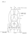
- Fig. 2 is a plan view of the vehicle.
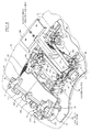
- Fig. 3 is a front view of an up-down moving device of the vehicle.
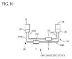
- Fig. 10 is a diagrammatic view of grip operation devices and a connecting device.
- Fig. 12 is a front view of a grip holding device of the grip operation device.
- Fig. 13 is an exploded view of an operation-device holding device of the connecting device.
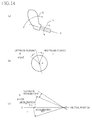
- Fig. 14 is illustrative views showing manners in which a grip of the grip operation device is operated.
- Fig. 15 is a view showing a control device that controls the vehicle as a whole, and peripheral devices connected to the control device.
- Fig. 22 is a view showing a target-left-right-lean-angle calculating portion of the control device.
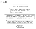
- Fig. 23 is a flow chart representing a braking and driving program that is stored in a storing portion of the control device.
- Fig. 24 is a flow chart representing a roll-over-guard-control-correction-amount calculating program that is stored in the storing portion.
- Fig. 25 is a flow chart representing a mode-dependent target-value determining program that is stored in the storing portion.
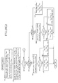
- Fig. 26(a) is a portion of a flow chart representing a priority-dependent control program that is stored in the storing portion.
- Fig. 26(b) is a remaining portion of the flow chart representing the priority-dependent control program.
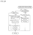
- Fig. 28 is a flow chart representing a turning-related front-rear-lean-angle limiting program that is stored in the storing portion.
- Fig. 30 is a flow chart representing a driving limiting program that is stored in a storing portion of a control device of another vehicle as another embodiment of the present invention.
- Fig. 31 is a flow chart representing a roll-over-guard control program that is stored in a storing portion of a control device of another vehicle as another embodiment of the present invention.
- Fig. 34 is a view showing a manner in which the target steering angle changes.
- Fig. 35 is a view showing a manner in which the vehicle turns in the case where a roll-over-guard control is performed in the vehicle.
- two grip operation devices i.e., a left grip operation device and a right grip operation device
- a left grip operation device and a right grip operation device 26, 28
- a left grip operation device and a right grip operation device 26, 28
- T a tread, T
- the present vehicle has the single front wheel 12, the overall size of the vehicle can be reduced as compared with a case where two front wheels are employed.
- the two up-down moving devices 50, 52 can be said to include respective motor units 81 each of which includes the up-down moving motor 66, the speed reducer 73, and the electromagnetic clutch 80.
- the zero point may be predetermined to be equal to a middle point of the above-described narrower limited movement ranges predetermined for the up-down moving devices 50, 52, or a point that is defined by the construction of the vehicle, e.g., the suspension springs 70.
- the pedal operation device 22 includes the above-described two pedals 24, 25; a main body 98; two pedal-pivot mechanisms 100, 102 that are provided on the main body 98; a connecting device 104 ( Fig. 8 ); and a locking device 106.
- the link device 104 is a trapezoidal link in which an effective length, L P2 , of the rod 142 is greater than a distance, L P1 , between the two first axis members 110, 110. Therefore, a downward pivotal motion of the inner portion of the left pedal 24 located inside the first axis line B L causes a downward pivotal motion of the outer portion of the right pedal 25 located outside the first axis line B R , such that an angle, ⁇ foot ', of the downward pivotal motion of the outer portion of the right pedal 25 is smaller than an angle, ⁇ foot , of the downward pivotal motion of the inner portion of the left pedal 24.
- the two first axis lines B L , B R extend like a capital, V, i.e., such that a distance therebetween increases in the frontward direction, i.e., E F > E B .
- each of the two first axis lines B L , B R is inclined relative to the centerline A by an angle, ⁇ (preferably, the angle ⁇ falls in the range of from 10 degrees to 15 degrees and is selected at, e.g., 13 degrees).
- the two first axis lines BL, BR are distant from each other by an angle, 2 ⁇ (preferably, the angle 2 ⁇ falls in the range of from 20 degrees to 30 degrees and is selected at, e.g., 26 degrees).
- each second axis line C L , C R substantially perpendicularly intersect the corresponding first axis lines B L , B R .
- each second axis line C L , C R is somewhat inclined such that as each second axis line C L , C R goes inward, each second axis line C L , C R goes rearward. Since each second axis line C L , C R is inclined in this way, respective portions of the two pedals 24, 25 that are located on the inner side of the corresponding first axis lines B L , B R and are located on the front side of the corresponding second axis lines C L , C R can have a large area. Therefore, the respective inner portions of the two pedals 24, 25 can be easily pivoted downward.
- the left and right pedal-pivot mechanisms 100, 102 have the respective potentiometers 130.
- the link device 104 defines a ratio of the pivotal-motion angle of one of the respective first axis members 110 of the two pedal-pivot mechanisms 100, 102 to that of the other first axis member 110. Therefore, if the pivotal-motion angle of one of the two pedals 24, 25 is detected, then that of the other pedal can be known.
- the two pedals 24, 25 be pivotable about the respective second axis lines C L , C R .
- the pressure sensors 128, 129 are replaced with strain gauges, then the strain gauges may be provided on each pedal 24, 25 per se so as to detect the operator's foot force applied thereto.
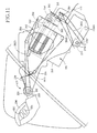
- the grip holding device 220 holds the grip 200 such that the grip 200 is rotatable or pivotable about each of a first axis line, D1, and a second axis line, D2, perpendicular to the first axis line D 1. As shown in Fig. 12 , the grip holding device 220 includes a universal joint 222.
- a base portion 223 that holds the grip 200 is held by a second axis member 225 extending parallel to the second axis line D2, such that the base portion 223 is pivotable about the second axis member 225 relative to a main body 224.
- a first axis member 228 is held by the base portion 223 such that the first axis member 228 is not rotatable relative to the base portion 223, and is rotatable about the first axis line D1 relative to the main body 224.
- the first axis member 228 is connected to a rotation transmitting portion 230 via the universal joint 222.
- the grip 200 is supported by the first axis member 228 such that the grip 200 is not rotatable relative to the first axis member 228 about the first axis line D1. Therefore, when the grip 200 is rotated about the first axis line D1, the first axis member 228 is rotated about the first axis line D1 and accordingly the rotation transmitting portion 230 is rotated.
- the second axis line D2 extends parallel to the widthwise direction of the body 10 and, when the grip 200 takes its neutral position, the first axis line D1 perpendicularly intersects the second axis line D2 and is somewhat inclined relative to the front-rear direction of the body 10.
- the two force applying mechanisms 190, 192 of the connecting device 180 have an identical construction including a reaction-force applying device that applies a reaction force corresponding to an angle of operation of the grip 200; a damping device that applies a damping force corresponding to a speed of operation of the grip 200; and an angle detecting device that detects the angle of operation of the grip 200.
- the two operation-device holding devices 194, 196 have respective identical constructions that are, however, symmetrical with each other with respect to the centerline A.
- the right operation-device holding device 196 that holds the right grip operation device 28 will be described in detail.
- the main body 224 is attached to the body 10 via the operation-device holding device 196, such that the main body 224 is movable relative to the body 10.
- the operation-device holding device 196 includes a body-side member 250 fixed to the body 10; two spline shafts 252, 254 attached to the body-side member 250; and two nuts 256, 258 that fit on the two spline shafts 252, 254, respectively.
- Each of the two spline shafts 252, 254 extends parallel to a third axis line, D3, and has a plurality of teeth extending parallel to the third axis line D3.
- Two pulleys 260, 261 are fixed to respective one end portions of the two spline shafts 252, 254; and two pulleys 262, 263 are fixed to respective one end portions of the two nuts 256, 258.
- the third axis line D3 is inclined relative to the body 10 such that as the third axis line D3 goes frontward, the axis line D3 goes upward.
- the main body 224 has two grooves 270, 272 that are opposed to the two spline shafts 252, 254, respectively; and two grooves 274, 275 that are opposed to the two nuts 256, 258, respectively.
- the grooves 270, 272 have respective diameters greater than those of the spline shafts 252, 254, and do not engage the teeth of the same 252, 254.
- the grooves 274, 275 have respective diameters greater than those of the nuts 256, 258.
- the spline shafts 252, 254 are respectively accommodated in the grooves 270, 272 and the nuts 256, 258 are respectively accommodated in the grooves 274, 275, such that respective rotations of the nuts 256, 258 and the spline shafts 252, 254 are permitted.
- each of the nuts 256, 258 is inhibited from being moved relative to the main body 224 along the third axis line D3 by two wall surfaces defining opposite axial ends of a corresponding one of the grooves 274,275.
- the movement of the main body 224 relative to the body-side member 250 is permitted by the movement of the nuts 256, 258 relative to the spline shafts 252, 254.
- the main body 224 can be moved between its advanced position and its retracted position at each of which the main body 224 can be inhibited from being moved relative to the body-side member 250 by a locking device 278.
- the advanced position of the main body 224 is a position where the plunger 278P is inserted into the front positioning hole 278H1; and the retracted position of the main body 224 is a position where the plunger 278P is inserted into the rear positioning hole 278H2.
- the locking device 278 is operated in response to operation of the switch 202.
- Two cables 284S, 284B are wound on the respective pulleys 260, 261 of the two spline shafts 252, 254 on which the two nuts 256, 258 fit, respectively.
- the two cables 284S, 284B are connected to the left grip operation device 26 via the above-described force applying devices 190, 192 and the left operation-device holding device 196.
- the rotation transmitting portion 230 When the grip 200 of the right grip operation device 28 is operated or rotated about the first axis line D1, the rotation transmitting portion 230 is rotated.
- the rotation of the rotation transmitting portion 230 is transmitted via the cable 282S to the pulley 262 of the nut 256, so that the nut 256 is rotated.
- the rotation of the nut 256 causes the rotation of the spline shaft 252 and the pulley 260.
- This rotation is transmitted via the cable 284S and the force applying device 190 to the spline shaft 252 of the left operation-device holding device 196 and further transmitted to the rotation transmitting portion 230 via the cable 282S.
- the rotation of the rotation transmitting portion 230 causes the rotation of the first axis member 228 about the first axis line D1.
- the force applying device 190 is commonly used for the respective rotations of the right grip operation device 28 and the left grip operation device 26 about the respective first axis lines D1.
- the reaction force or the like is applied to the one grip 200 and the angle of rotation of the grip 200 is detected.
- the second axis member 225 When the grip 200 of the right grip operation device 28 is operated or pivoted about the second axis line D2, the second axis member 225 is rotated. The rotation of the second axis portion 225 is transmitted via the cable 282B to the pulley 263 of the nut 258, so that the nut 258 is rotated. The rotation of the nut 258 causes the rotation of the spline shaft 254 and the pulley 261. This rotation is transmitted via the cable 284B and the force applying device 192 to the spline shaft 254 of the left operation-device holding device 194 and further transmitted to the second axis member 225 via the cable 282B. The rotation of the second axis member 225 causes the rotation of the base portion 223 about the second axis line D2.
- the left grip 200 is rotated about the second axis line D2, without needing the operator's operation.
- the force applying device 192 is commonly used for the respective pivotal motions of the right grip operation device 28 and the left grip operation device 26 about the respective second axis lines D2.
- the reaction force or the like is applied to the grip 200 and the angle of rotation of the grip 200 is detected.
- the two grips 200 are connected to each other by the connecting device 180, in the interlocked manner in which the transmission of the rotation of one of the two grips 200 about the corresponding first axis line D1 to the other grip 200 and the transmission of the rotation of one of the two grips 200 about the corresponding second axis line D2 to the other grip 200 occur independent of each other.
- the rotation transmitting device 182 includes the cable 284S and the pulley 260; and the rotation transmitting device 184 includes the cable 284B and the pulley 261.
- the grips 200 provide a steering-instructing operable member, an acceleration-deceleration-instruction operable member, or a common member functioning as each of the steering-instructing operable member and the acceleration-deceleration-instructing operable member.
- the cable 173 is pulled by the main body 224 and the locking device 106 is placed at the unlocking position R2; and when the main body 224 is positioned at the advanced position, the cable 173 is pulled by the spring 174 and the locking device 106 is placed at the locking position R1.
- Each of the two operation-device holding devices 194, 196 may be arranged such that the position of the main body 224 relative to the body 10 can be fixed at an arbitrary position between the retracted position and the advanced position. In this case, the operation can finely adjust, according to his or her preference or build, respective positions where the two grips 200 are operated.
- the left and right grip operation devices 26, 28 are employed. However, it is not essentially needed to employ the two grip operation devices. That is, it is possible to employ only one grip operation device.
- the grips 200 constitute the common member functioning as each of the steering-instructing operable member and the acceleration-deceleration-instructing operable member. That is, it is possible to employ individual members that function as the steering-instructing operable member and the acceleration-deceleration-instructing operable member, respectively.
- the vehicle constructed as described above is controlled by a control device 300.
- the control device 300 is essentially constituted by a computer including an implementing portion 302, a storing portion 304, and an input-output portion 306.
- the input-output portion 306 is connected to a grip-operation detecting device 310 that detects an operation state of the grips 200; a pedal-operation detecting device 312 that detects an operation state of the pedals 24, 25; a posture-change detecting device 314 that detects a change of a posture of the vehicle; the switches 202, 204; an indicator 320; and the respective solenoids (not shown in Fig. 15 ) of the left and right locking devices 278.
- the input-output portion 306 is connected to the steering actuator 30, the driving-braking actuators 40, 42, and the suspension actuators 50, 52 via respective motor control devices (i.e., respective motor servo amps) 322, 324, 326.
- the grip-operation detecting device 310 includes a steering-instruction detecting portion (i.e., a steering-related angle sensor) 316 that detects an angle of rotation, ⁇ LAT , of the grips 200 about the first axis line D1; and an acceleration-deceleration-instruction detecting portion (i.e., an acceleration-deceleration-related angle sensor) 317 that detects an angle of rotation, ⁇ LON , of the grips 200 about the second axis line D2.
- the acceleration-deceleration-instruction detecting portion 317 also functions as a backward-movement-instruction detecting portion 318.
- each grip 200 can be rotated about the first axis line D1 as indicated at arrow, A, and about the second axis line D2 as indicated at arrow, B.
- a rightward rotation of the grip 200 from its neutral position about the first axis line D1 represents an instruction of a rightward steering
- a leftward rotation of the grip 200 from its neutral position represents an instruction of a leftward steering.
- the neutral position of the grip 200 is inclined inward by an appropriate angle (preferably, this angle falls in a range of from 10 degrees to 20 degrees and is equal to, e.g., 15 degrees).
- the rotation angle ⁇ LAT of the grip 200 as measured from its neutral position represents an instructed amount of steering.
- an angle of rightward turning takes a positive value and an angle of leftward turning takes a negative value.
- an angle of steering of the steering wheel 12 described later, it is assumed that an angle of rightward steering takes a positive value and an angle of leftward steering takes a negative value; and regarding an angle of inclination of the vehicle, described later, it is assumed for convenience that an angle of rightward inclination takes a positive value and an angle of leftward inclination takes a negative value.
- the pedal-operation detecting device (i.e., the posture-instruction detecting device) 312 includes the above-described potentiometers 130 that detect the angle ⁇ foot of pivotal motion of the pedals 24, 25, and the four pressure sensors 128, 129 that detect the foot forces applied to the pedals 24, 25.
- the pivotal-motion angle ⁇ foot detected by the potentiometers 130 represents an operator's instruction to incline the body 10 and the wheels 14, 16 in the lateral direction.
- a greater absolute value of angle ⁇ foot represents an operator's instruction to incline the body 10 and the wheels 14, 16 by a greater absolute value of angle in the lateral direction.
- the downward pivotal motion of the inner portion of the left pedal 24 represents an operator's instruction to incline the body 10 in the rightward direction
- the downward pivotal motion of the inner portion of the right pedal 25 represents an operator's instruction to incline the body 10 in the leftward direction. That is, the direction in which the vehicle's body 10 is inclined by the operation of the pedals 24, 25 is the same as the direction in which the operator's body is inclined when the operator operates the pedals 24, 25.
- a positive sign is given to angles of pivotal motion of the left pedal 24 (that represent an instruction to incline the body 10 in the rightward direction); and a negative sign is given to angles of pivotal motion of the right pedal 25 (that represent an instruction to incline the body 10 in the leftward direction).
- a negative sign is given to values detected by the two front foot-force sensors 129 out of the four foot-force sensors 128, 129; and a positive sign is given to values detected by the two rear foot-force sensors 128. Therefore, if a sum, or an average, of the values detected by the four foot-force sensors 128, 129 is negative, the sum or average represents an instruction to incline the body 10 in the forward direction; and if the sum or the average is positive, the sum or average represents an instruction to incline the body 10 in the backward direction. A greater absolute value of the sum or the average represents an instruction to incline the body 10 by a greater absolute value of angle.
- the sum, or the average, of the values detected by the four foot-force sensors 128, 129 (i.e., the value obtained by processing the values detected by the four pressure sensors 128, 129) will be simply referred to as the foot-force value, P foot .
- a positive sign is given to angles of inclination of the body 10 from a reference posture (i.e., a reference position) in the rearward direction, i.e., angles of the rearward inclination in which the rear portion of the body 10 is moved downward relative to the front portion thereof; and a negative sign is given to angles of inclination of the body 10 from the reference posture in the forward direction, i.e., angles of the forward inclination in which the rear portion of the body 10 is moved upward relative to the front portion thereof.
- each of the switches 202 is operated when a corresponding one of the grip operation devices 26, 28 is moved relative to the body 10; and each of the switches 204 is operated when either the comfort mode or the performance mode is selected.
- the comfort mode is a mode in which the posture of the body 10 is controlled irrespective of whether the pedals 24, 25 are operated
- the performance mode is a mode in which the posture of the body 10 is controlled based on the operation of the pedals 24, 25. Therefore, when the operator selects the comfort mode, the operator needs to move the main bodies 224 to their retracted positions. In this state, the pedal operation device 22 inhibits the operation of the pedals 24, 25. On the other hand, when the operator selects the performance mode, the operator needs to move the main bodies 224 to their advanced positions. In this state, the pedal operation device 22 permits the operation of the pedals 24, 25.
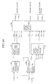
- control device 300 First, an overall flow of the operation of the control device 300 is briefly described by reference to the diagrammatic view of Fig. 16 .
- a target-vehicle-speed calculating portion 350 calculates a target running speed, V T , of the vehicle based on the rotation angle ⁇ LON of the grips 200 with respect to the front-rear direction and an actual running speed, Vs, of the vehicle.
- a target-wheel-speed calculating portion 352 calculates respective target rotation speeds, W TL , W TR , of the left and right driving wheels 14, 16 based on the target running speed V T of the vehicle and a target-steering-angle-related reference value, ⁇ Tref1 (this value ⁇ Tref1 is different from a target steering angle outputted to a target-motor-torque calculating portion 354).
- the target-motor-torque calculating portion 354 calculates respective target torques, M WL , M WR , of the two driving motors 44 based on the target rotation speeds W TL , W TR of the left and right driving wheels 14, 16 and respective actual rotation speeds W CL , W CR of the same 14, 16.
- the target torques M WL , M WR may be drive torques or brake torques.
- Information representing the calculated target torques M WL , M WR is supplied to the two motor control devices (i.e., motor servo amps) 324, respectively.
- the two motor control devices 324 control the respective operating states of the two driving motors 44 (i.e., output respective PWM signals to the same 44) so that respective actual torques thereof approach the corresponding target torques M WL , M WR .
- the motor control devices 324 supply, to the control device 300, information representing the actual rotation speeds W CL , W CR of the driving wheels 14, 16 and the drive or brake torques actually applied to the same 14, 16.
- the actual running speed of the vehicle will be simply referred to as the "vehicle speed" V S .
- the vehicle speed V S is determined based on an average of the respective peripheral speeds of the driving wheels 14, 16.
- a rotation speed of each wheel 14, 16 may be obtained as a peripheral speed or a rotation angular speed thereof, and a vehicle speed may be obtained based on the respective rotation angular speeds of the driving wheels 14, 16.
- a target-front-steering-angle calculating portion 356 calculates the target steering angle ⁇ T based on the actual vehicle speed V S , the rotation angle ⁇ LAT of the grips 200 with respect to the lateral direction, respective actual up-down strokes, H CL , H CR , of the left and right rear wheels 14, 16 relative to the body 10, and the roll rate ⁇ ; and the target-motor-torque calculating portion 354 calculates a target drive torque, M ⁇ , of the steering motor 32 based on the target steering angle ⁇ T and an actual steering angle, ⁇ C , of the steering wheel 12.
- Information representing the target drive torque M ⁇ is supplied to the motor control device (i.e., motor servo amp) 322.
- the motor control device 322 controls the operating state of the steering motor 32 so that an actual drive torque thereof approaches the target drive torque M ⁇ .
- the motor control device 322 supplies, to the control device 300, information representing the actual steering angle ⁇ C of the steering wheel 12 and an actual load applied to the same 12.
- the target-front-steering-angle calculating portion 356 calculates the target-steering-angle reference value ⁇ Tref1 and another target-steering-angle reference value, ⁇ Tref2 , that are to be supplied to the target-wheel-speed calculating portion 352 and a target-up-down-stroke calculating portion 358, respectively.
- the target-up-down-stroke calculating portion 358 calculates, in the comfort mode, respective target up-down strokes, H TL , H TR , of the left and right wheels 14, 16 relative to the body 10, based on the actual vehicle speed V S and a vehicle-speed deviation, ⁇ V (i.e., a value obtained by subtracting the actual vehicle speed V S from the target vehicle speed V T ), and calculates, in the performance mode, respective target up-down strokes H TL , H TR based on the actual vehicle speed V S , the vehicle-speed deviation ⁇ V, the pedal rotation angle ⁇ foot , and the foot force P foot .
- ⁇ V i.e., a value obtained by subtracting the actual vehicle speed V S from the target vehicle speed V T
- the target-motor-torque calculating portion 354 calculates respective target drive torques, M HL , M HR , of the two up-down moving motors 66 based on the respective target up-down strokes H TL , H TR and the respective actual up-down strokes H CL , H CR .
- Information representing the two target drive torques M HL , M HR is supplied to the two motor control devices (i.e., motor servo amps) 326, respectively.
- the motor control devices 326 control the respective operation states of the up-down moving motors 66 so that respective actual torques thereof approach the respective target torques M HL , M HR .
- the motor control devices 326 supply, to the control device 300, information representing the respective actual up-down strokes H CL , H CR of the driving wheels 14, 16 relative to the body 10.
- an up-down stroke may be obtained based on not an amount of rotation of each up-down moving motor 66 but a position of each wheel holding member 64 relative to the corresponding guide members 60, 62 that is detected by, e.g., a potentiometer.
- a posture of the body 10 with respect to the lateral direction and a posture of the body 10 with respect to the front-rear direction can be controlled by controlling the up-down moving devices 50, 52.
- the posture of the body 10 with respect to the lateral direction is controlled by controlling an angle, ⁇ L , of inclination of a straight line, Y B , defining an up-down direction of the body 10, relative to a normal line, Z, of a road surface.
- ⁇ L the inclination angle of the body 10 with respect to the lateral direction
- the body 10 and the left and right driving wheels 14, 16 are inclined by making different the respective positions of the wheels 14, 16 relative to the body 10 in the up-down direction.
- respective positions of the left and right driving wheels 14, 16 that are taken, when the main switch of the vehicle is changed from the OFF state to the ON state, relative to the body 10 in a steady state of the vehicle defined as a stopped state thereof or a constant-speed running state thereof are referred to as reference positions where the pitch angle (i.e., front-rear lean angle) ⁇ pit is equal to zero.
- the straight line X 0 defines the front-rear direction of the vehicle in the steady state thereof.
- Respective deviations of the reference positions from the zero point can be obtained based on respective accumulated values of the up-down strokes. If the deviations of the reference positions from the zero point are corrected, e.g., when the up-down strokes reach their limits, those deviations can be accurately obtained.
- a target-vehicle-speed obtaining portion 362 calculates a target vehicle speed, V T1 , based on the rotation angle ⁇ LON ( ⁇ D or ⁇ R ).
- the thus obtained target vehicle speed V T1 is processed by a low-pass filter 364, and then is outputted (as the target vehicle speed V T ).
- the target-vehicle-speed calculating portion 350 outputs a deviation ⁇ V (V T1 - V S ) of the vehicle speed that is obtained by subtracting the actual vehicle speed V S from the target vehicle speed V T1 .
- the thus obtained target vehicle speed V T2 is processed by a low-pass filter 370, and then is outputted (as the target vehicle speed V T ).
- the target-vehicle-speed calculating portion 350 outputs a deviation ⁇ V (V T2 - V S ) of the vehicle speed that is obtained by subtracting the actual vehicle speed V S from the target vehicle speed V T2 .
- the target-wheel-speed calculating portion 352 receives the target vehicle speed V T outputted by the target-vehicle-speed calculating portion 350, and the target-steering-angle reference value ⁇ Tref1 (containing a delay), described later.
- a difference calculating portion 380 calculates, based on the target-steering-angle reference value ⁇ Tref1 and the target vehicle speed V T , a difference of respective rotation speeds of the left and right wheels 14, 16 when the vehicle turns, and outputs respective difference-dependent target speeds, V WTL , V WTR , of the wheels 14, 16.
- a right-driving-wheel target-wheel-speed calculating portion 382 calculates a target speed W TR of the right driving wheel 16 based on the difference-dependent target speed V WTR of the right wheel 16 and the target vehicle speed V T
- a left-driving-wheel target-wheel-speed calculating portion 384 calculates a target speed W TL of the left driving wheel 14 based on the difference-dependent target speed V WTL of the left wheel 14 and the target vehicle speed V T .
- the thus obtained target wheel speeds W TL , W TR are outputted after, first, those speeds are processed by respective low-pass filters 386 and then the speeds whose absolute values are smaller than a pre-set value are removed (i.e., are changed to zero) by respective processing portions 388.
- Respective portions of the respective operations of the target-vehicle-speed calculating portion 350, the target-wheel-speed calculating portion 352 and the target-motor-torque calculating portion 354 will be briefly described by reference to the flow chart shown in Fig. 23 .
- a target vehicle speed V T is calculated based on the rotation angle ⁇ LON of the grips 200 with respect to the front-rear direction, and the actual vehicle speed V S .
- respective target speeds W TL , W TR of the left and right driving wheels 14, 16 are calculated based on the target vehicle speed V T and the target-steering-angle reference value ⁇ Tref1 .
- respective target drive torques M WL , M WR are calculated based on the respective target wheel speeds W TL , W TR and respective actual wheel speeds W CL , W CR , and are outputted.
- the respective target wheel speeds W TL , W TR outputted by the target-wheel-speed calculating portion 352 are equal to each other.
- the target speed W TR of the right driving wheel 16 is lower than the target speed W TL of the left driving wheel 14; and when the vehicle turns leftward, the target speed W TL of the left driving wheel 14 is lower than the target speed W TR of the right driving wheel 16.
- the target-vehicle-speed obtaining portion 362 of the control device 300 constitutes a target-vehicle-speed determining portion; the target-deceleration obtaining portion 366 of the control device 300 constitutes a target-deceleration determining portion; and the target-motor-torque calculating portion 354 and the target-wheel-speed calculating portion 352 of the control device 300 cooperate with each other to constitute a target-value-dependent driving-braking control portion.
- the motor control devices 324 cooperate with each other to constitute a driving-braking control device.
- a target vehicle speed is determined based on the rotation angle ⁇ LON ( ⁇ R ) of the grips 200.
- a target vehicle speed be determined at a pre-set speed irrespective of the magnitude of the rotation angle ⁇ LON .
- a first target-steering-angle obtaining portion 394 obtains a target steering angle ⁇ S1 , based on the rotation angle ⁇ LAT and the actual vehicle speed V S , such that the absolute value of the target steering angle ⁇ S1 is greater when the absolute value of the rotation angle ⁇ LAT is great than when the absolute value of the rotation angle ⁇ LAT is small, and such that, on the assumption that the rotation angle ⁇ LAT does not change, the target steering angle ⁇ S1 is smaller when the actual vehicle speed V S is high than when the actual vehicle speed V S is low.
- an output (i.e., a target steering angle ⁇ S3 ) from the multiplying portion 400 is made smaller when the absolute value of the deviation ⁇ V is great than when it is small, which leads to improving the running stability of the vehicle.
- the signal (i.e., target steering angle) ⁇ S3 outputted from the multiplying portion 400 is supplied via a low-pass filter 402 to a processing portion 404. Since the low-pass filter 402 produces a large delay, the target steering angle ⁇ T is outputted with a delay after the operation or rotation of the grips 200 by the angle ⁇ LAT about the respective first axis lines D1. Consequently the steering wheel 12 is steered with a delay after the operation or rotation of the grips 200.
- the target-steering-angle reference value ⁇ Tref1 is supplied to the target-wheel-speed calculating portion 352; and the target-steering-angle reference value ⁇ Tref2 is supplied to the target-up-down-stroke calculating portion 358.
- a coefficient obtaining portion 408 obtains a coefficient based on the actual vehicle speed V S .
- This coefficient falls within a range of from 0 to -1. In the case where the vehicle runs forward, the absolute value of this coefficient is greater when the actual vehicle speed V S is high than when the speed V S is low; and in the case where the vehicle moves backward, this coefficient is kept at zero.
- This coefficient is used as a time constant, T 1 , that is used in obtaining a target steering angle when an opposite-direction steering is carried out.
- a processing portion 404 processes, using a transfer function, T 1 (s)/T 2 (s), the input value ⁇ TO (i.e., the signal outputted from the low-pass filter 402).
- This transfer function is expressed as (T 1 ⁇ s + 1)/ (T 2 ⁇ s + 1), and the time constant T 1 is variable.
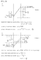
- the differential value s of the target steering angle ⁇ TO is equal to zero before time t1 and after time 2, but is changed during the time period between time t1 and time t2, as shown in Fig. 33(b) , such that the differential value s is first increased, subsequently kept constant, and then decreased. Consequently the values ⁇ O outputted by the processing portion 404 are changed as shown in Fig. 33(c) .
- Fig. 34 shows an example of a time-wise change of the output value (i.e., the target steering angle ⁇ O ).
- the target steering angle ⁇ O is first changed in a direction opposite to the direction of changing of the target steering angle ⁇ TO , and subsequently is kept at a constant value (i.e., a value, ⁇ TO2 , after the changing, shown in Fig. 33(c) ).
- a roll moment is produced by a reaction force against a lateral force applied to a tire of the wheel 12.
- this roll moment can be utilized to incline reliably and quickly the body 10 in a radially inward direction of its turning circle after the changing (i.e., in a radially outward direction of a turning circle when the steering wheel 12 is steered in the opposite direction).
- the vehicle can run even in a slalom mode or can turn quickly.
- a centrifugal force applied to the body 10 is greater when the vehicle speed V is high than when the vehicle speed V is low.
- a force against the inclination of the body 10 in the radially inward direction of its turning circle is greater when the vehicle speed V is high than when the vehicle speed V is low.
- the angle of steering in the opposite direction is made greater when the vehicle speed V is high than when the vehicle speed V is low. Therefore, even if the vehicle speed V may be high, the body 10 can be reliably inclined in the radially inward direction of its turning circle.
- the angle of steering in the opposite direction is made greater when the absolute value of the differential value of the target steering angle ⁇ TO (i.e., the speed of operation of the grips 200 about the respective first axis lines D1, or the speed of change of the rotation angle ⁇ LAT ) is great than it is small. Therefore, when the speed of operation of the grips 200 is high, the body 10 can be quickly inclined in the radially inward direction of its turning circle. Thus, the operator's request can be quickly satisfied.
- the rotation of the steering motor 32 does not substantially change because of the inertia of the motor 32.
- the differential value is small and the angle of steering in the opposite direction is small, the change of the target drive torque M ⁇ is small.
- the operation state of the steering motor 32 does not change, and the opposite-direction steering does not occur.
- the speed of operation or rotation of the grips 200 about the respective first axis lines D1 is lower than a pre-set value, then the steering wheel 12 is not steered in the direction opposite to the direction corresponding to the operation of the grips 200; and if the operation speed is not lower than the pre-set value, then the wheel 12 is steered in the opposite direction.
- a roll-over-guard control portion i.e., a roll-over-guard-control correction-value calculating portion
- the roll-over guard control is started when it is judged that the vehicle is in a roll-over state, and is ended when the roll-over state has ended or when the roll-over guard control is not needed any longer.
- the roll-over guard control is performed by making smaller the absolute value of the steering angle of the steering wheel 12.
- the roll-over guard control will be described by reference to the flow chart shown in Fig. 24 .
- Step S21 it is judged whether a roll-over-guard-control flag is set. If the roll-over-guard-control flag is reset, the control goes to Step S22 to estimate a roll rate, ⁇ ', based on respective speeds of change of the respective actual up-down strokes H CL , H CR of the left and right driving wheels 14,16; and at Step S23, the estimated roll rate ⁇ ' obtained at Step S22 is compared with the value ⁇ actually detected by the roll sensor 332.
- Step S29 the control goes to Step S29 to judge whether an ending condition has been met. If a negative judgment is made at Step S29, the control goes to Steps S25 through S28. On the other hand, if a positive judgment is made at Step S29, the control goes to Step S30 to reset the roll-over-guard-control flag and change the roll-over-guard control-correction amount ⁇ RO to zero. ⁇ RO ⁇ 0
- the roll-over-guard control portion 406 outputs the roll-over-guard control amount ⁇ ROS as the roll-over-guard-control correction amount ⁇ RO .
- the processing portion 404 outputs, when the grips 200 are operated, the opposite-direction target steering angle ⁇ 0 corresponding to the speed of operation of the grips 200. That is, even if the operator may perform the avoidance steering, the processing portion 404 outputs the target steering angle ⁇ 0 to steer the vehicle in the opposite direction. However, it is not desirable to steer, in the roll-over state, the vehicle in the opposite direction.
- the steering in the opposite direction is not performed because the roll-over-guard-control correction amount ⁇ RO to decrease the absolute value of the target steering angle ⁇ T0 is outputted. Even in this case, however, if the absolute value of the change amount ⁇ T0 of the target steering angle ⁇ T0 by the operator becomes not smaller than the absolute value of the roll-over-guard control amount ⁇ ROS , then the roll-over-guard control is ended. Thus, the target steering angle ⁇ T is determined, and the steering wheel 12 is steered, according to the operator's operation of the grips 200.
- the roll-over-guard control portion 406 When the vehicle is not in the roll-over state, the roll-over-guard control portion 406 outputs the roll-over-guard-control correction amount ⁇ RO that is equal to zero. Therefore, the opposite-direction steering is performed.
- the target-front-steering-angle calculating portion 356, the target-motor-torque calculating portion 354, a portion of the storing portion 304 that stores the roll-over-guard control program represented by the flow chart of Fig. 24 , and the implementing portion 302 cooperate with each other to constitute a steering control device.
- This steering control device also functions as a steering-operation-dependent steering control portion.
- the processing portions 404, 410 and the target-motor-torque calculating portion 354 cooperate with each other to constitute an opposite-direction steering portion; and the processing portions 404, 410 cooperate with each other to constitute an opposite-direction steering-angle determining portion.
- the low-pass filter 402 and the target-motor-torque calculating portion 354 cooperate with each other to constitute an after-posture-control steering control portion.
- the target-up-down-stroke calculating portion 358 receives the values ⁇ foot , P foot detected by the pedal-operation detecting device 312, the vehicle-speed deviation ⁇ V, the actual vehicle speed V S , and the target-steering-angle reference value ⁇ Tref2 , and outputs the respective target up-down strokes H TL , H TR of the left and right driving wheels 14, 16.
- the correction angle ⁇ H is added to the target front-rear lean angle ⁇ Tpit1 to provide a target front-rear lean angle ⁇ Tpit , which is inputted to a request integrating portion 414 that calculates, based on the target front-rear lean angle ⁇ Tpit and the target left-right lean angle ⁇ TL , respective target up-down strokes H TL , H TR of the left and right driving wheels 14, 16.
- the target-front-rear-lean-angle calculating portion 410 includes a processing portion 420 that calculates, based on the vehicle-speed deviation ⁇ V and the actual vehicle speed V S , a target pitch angle ⁇ T1 .
- the target pitch angle ⁇ T1 is made negative ( ⁇ T1 ⁇ 0) and accordingly the left and right wheels 14, 16 are moved to the rebound side relative to the body 10.
- the absolute value of the target pitch (lean) angle ⁇ T1 is increased as the vehicle-speed deviation ⁇ V is increased, because the inertia force increases as the acceleration increases.
- the target pitch angle ⁇ T1 is made positive ( ⁇ T1 > 0) and accordingly the left and right wheels 14, 16 are moved to the bound side relative to the body 10.
- the target pitch (lean) angle ⁇ T1 is increased as the absolute value of the vehicle-speed deviation ⁇ V is increased.
- the absolute value of the target pitch (lean) angle ⁇ T1 is decreased as the actual vehicle speed V S is increased, because it is not desirable that when the vehicle speed V S is high, the front-rear-direction lean angle be increased.
- the gravity center G of the present vehicle is located on the vertical line passing through the gravity center of the triangle connecting the respective ground-contact points of the three wheels 12, 14, 16 to each other. If the gravity center G is located inside an inscribed circle of the triangle, the vehicle is stable. Therefore, even if the gravity center G may be moved depending upon the running state of the vehicle, the vehicle is kept stable so long as the gravity center G remains inside the inscribed circle.
- a lateral-G estimating portion 422 estimates, based on the actual vehicle speed V S and the target-steering-angle reference value ⁇ Tref2 , a lateral acceleration Gy.
- the reference value ⁇ Tref2 is inputted to the lateral-G estimating portion 422, the reference value ⁇ Tref2 is subjected to a processing step in which the value ⁇ Tref2 whose absolute value is considerably small is changed to zero.
- the thus estimated lateral acceleration Gy is processed by an absolute-value obtaining portion 424 (i.e., an absolute value of the acceleration Gy is obtained); and a coefficient, K p2 , is obtained by a coefficient obtaining portion 426.
- the coefficient K p2 falls within a range of from 0 to 1, and increases as the absolute value of the lateral acceleration Gy decreases. That is, the coefficient K p2 approaches 1 as the absolute value approaches 0, and it approaches 0 as the absolute value increases.
- the absolute value of the lateral acceleration Gy is great, that is, if the vehicle is turning and the turning radius is small or the running speed of the vehicle is high, it is desirable that the front-rear lean angle be small. Therefore, the coefficient K p2 approaches 0 as the absolute value increases. Since this is true with both the leftward turning and the rightward turning, the absolute value of the lateral acceleration Gy is used.
- the target front-rear lean angle ⁇ Tpit1 is basically selected at zero; but in the performance mode, even if the vehicle-speed deviation ⁇ V may be zero, the target front-rear lean angle ⁇ Tpit1 may be selected at a value different from zero, depending upon the foot force P foot applied to the pedals 24, 25 by the operator. In other words, the control of the posture of the vehicle with respect to the front-rear direction can be quickly performed.
- the target front-rear lean angle ⁇ Tpit1 is not selected based on the foot force P foot only, but is selected based on the vehicle-speed deviation ⁇ V as well as the foot force P foot . Therefore, the posture of the vehicle with respect to the front-rear direction can be appropriately controlled according to the operator's operation of the pedals 24, 25.
- the left-right-lean-angle calculating portion 412 includes a processing portion 450 that obtains, based on the lateral acceleration Gy, an assist angle, ⁇ LA1 .
- the assist angle ⁇ LA1 is multiplied by a gain, K p3 , to obtain an assist angle, ⁇ LA2 . If the absolute value of the lateral acceleration Gy is great and accordingly the centrifugal force is great, it is required that a centripetal force against the centrifugal force be great. Meanwhile, if the absolute value of the left-right lean angle (i.e., camber angle) of the left and right wheels 14, 16 is great, then the centripetal force (i.e., camber trust force) is also great.
- the absolute value of the assist angle i.e., target left-right lean angle
- ⁇ LA1 the absolute value of the assist angle (i.e., target left-right lean angle) ⁇ LA1 is made greater when the absolute value of the lateral acceleration Gy is great than when it is small.
- the target left-right lean angle ⁇ LA1 is made smaller when the actual vehicle speed V S is high than when the speed V S is low.
- a gain for the pedal pivot angle ⁇ foot is selected at zero. Therefore, a processing portion 456 saturates the assist angle ⁇ LA2 , and the thus processed angle is outputted as the target left-right lean angle ⁇ TL .
- a processing portion 454 obtains, based on the pivot angle ⁇ foot , a target left-right lean angle ⁇ y .
- the absolute value of the target left-right lean angle ⁇ y is increased as the absolute value of the pivot angle ⁇ foot is increased, because the operator has an intension to lean the body 10 largely in the left-right direction when the pivot angle ⁇ foot is great.
- the absolute value of the target left-right lean angle ⁇ y is made smaller when the actual vehicle speed V S is high than when the speed V S is low.
- the assist angle ⁇ LA2 is added to the target left-right lean angle ⁇ y determined based on the pivot angle ⁇ foot , the thus obtained value is saturated by the processing portion 456 and then is outputted as the target left-right lean angle ⁇ TL .
- the gain K p3 is selected at a value smaller than the value of gain K p3 used in the comfort mode.
- the gravity center G thereof is moved leftward because of the centrifugal force (i.e., the lateral acceleration Gy).
- the centrifugal force i.e., the lateral acceleration Gy.
- the gravity center G is moved rightward and can be prevented from being moved out of the inscribed circle of the triangle.
- the amount of leftward movement of the gravity center G can be decreased.
- a differential-value obtaining portion 458 obtains a differential value of the lateral acceleration Gy inputted to the target-left-right-lean-angle calculating portion 412; an absolute-value obtaining portion 459 obtains an absolute value of the differential value; and a processing portion 460 obtains a correction angle, ⁇ H , based on the absolute value of the differential value.
- the correction angle ⁇ H is made greater when the absolute value of the differential value of the lateral acceleration Gy is great than when it is small.
- the target-left-right-lean-angle calculating portion 412 outputs the target left-right lean angle ⁇ TL and the correction angle ⁇ H .
- the correction angle ⁇ H is for compensating for the change of height position of the gravity center G caused by the control of the left-right lean angle.
- the control of the left-right lean angle i.e., when the respective positions of the left and right wheels 14, 16 relative to the body 10 in the up-down direction are changed, an average height position of a rear portion of the body 10 is also changed. This change corresponds to the change of the front-rear lean angle. Therefore, it can be said that the correction angle ⁇ H is a portion of the front-rear lean angle.
- the correction angle ⁇ H is outputted in the case where the absolute value of the differential value of the lateral acceleration Gy is greater than zero, or where the absolute value is greater than a pre-set value (greater than zero), i.e., in the case where a steering operation is carried out (the direction of turning is changed and the posture of the vehicle with respect to the lateral direction is changed).
- Step S31 it is judged whether the selected mode is the comfort mode or the performance mode. If the comfort mode has been selected, then the control goes to Step S32 to select the gains K p1 , K p3 at respective values each corresponding to the comfort mode. Step S32 is followed by Step S33 to obtain a target front-rear lean angle ⁇ Tpit based on the vehicle-speed deviation ⁇ V, and obtain a target left-right lean angle ⁇ TL based on the lateral acceleration Gy. Then, the control goes to Step S34 where the request integrating portion 414 determines target strokes H TL , H TR of the left and right wheels 14, 16, which are outputted to the target-motor-torque calculating portion 354.
- Step S35 the control goes to Step S35 to select the gains K p1 , K p3 at respective values that each correspond to the performance mode and are smaller than the respective values corresponding to the comfort mode.
- Step S35 is followed by Step S36 to obtain a target front-rear lean angle ⁇ Tpit based on the vehicle-speed deviation ⁇ V and the foot force P foot , and obtain a target left-right lean angle ⁇ TL based on the lateral acceleration Gy and the pedal-pivot angle ⁇ foot .
- the control goes to Step S36 where the request integrating portion 414 determines target strokes H TL , H TR of the left and right wheels 14, 16, which are outputted to the target-motor-torque calculating portion 354.
- the present vehicle enables the operator to select the comfort mode or the performance mode, which improves the operability of the vehicle.
- the present vehicle may be modified such that the operator can select respective desirable values of the gains K p1 , K p3 .
- the vehicle may be modified such that when the performance mode is selected, the target left-right lean angle ⁇ TL and the target front-rear lean angle ⁇ Tpit are not determined based on the respective magnitudes of the pedal-pivot angle ⁇ foot and the foot force P foot , but are selected at respective pre-set values in a manner in which the operation of the pedals 24, 25 is utilized as a trigger, and the detection of the pedal-pivot angle ⁇ foot is used as a signal to indicate that the operator has an intension to incline the body 10 in the left-right direction, or the detection of the foot force P foot is used as a signal to indicate that the operator has an intension to incline the body 10 in the front-rear direction.
- This is due to the fact that it may be somewhat difficult for the operator to adjust the respective magnitudes of the pedal pivot angle and the foot force by operating, with his or her feet, the pedals.
- the request adjusting potion 414 has a basic rule that respective target strokes (hereinafter, referred to as the pitch-related target strokes) H TPR , H TPL are determined based on the target front-rear lean angle ⁇ Tpit , respective target strokes (hereinafter, referred to as the lean-related target strokes) H TLR , H TLL are determined based on the target front-rear lean angle ⁇ TL , and a sum of the pitch-related target stroke H TPR and the corresponding lean-related target stroke H TLR , and a sum of the pitch-related target stroke H TPL and the corresponding lean-related target stroke H TLL are outputted as respective target strokes H TR , H TL of the left and right wheels 14, 16.
- respective target strokes hereinafter, referred to as the pitch-related target strokes
- H TPL are determined based on the target front-rear lean angle ⁇ Tpit
- respective target strokes hereinafter, referred to as the lean-
- the target-motor-torque calculating portion 354 calculates, based on the target strokes H TL , H TR and the actual strokes H CL , H CR , respective target torques M TL , M TR of the left and right up-down moving motors 66, and outputs the thus calculated target torques M TL , M TR .
- tan ⁇ L 2 ⁇ H / T where T is the tread of the vehicle.
- a stroke H R of the wheels 14, 16 is positive and accordingly a value tan ⁇ L and a left-right lean angle ⁇ L are also positive.
- a stroke H of the wheels 14, 16 is positive and accordingly a value tan ⁇ pit and a front-rear lean angle ⁇ pit are also positive.
- a target stroke H T of the wheels 14, 16 can be obtained based on the target left-right lean angle ⁇ TL and the target front-rear lean angle ⁇ Tpit .
- the strokes obtained based on the front-rear lean angle may mean either the strokes obtained while the left-right lean angle is taken into account, or the strokes obtained while the left-right lean angle is not taken into account.
- the steering wheel 12 is steered in the opposite direction. That is, during the control of inclination of the body 10 in the radially inward direction of the turning circle, the steering wheel 12 is steered in the opposite direction. Therefore, the body 10 can be quickly and reliably inclined radially inward of the turning circle, owing to the posture control and a roll moment caused by the steering of the wheel 12 in the opposite direction.
- pitch-related target strokes determined based on the front-rear lean angle corresponding to the braking have priority; and in the case where driving and turning simultaneously occur, lean-related target strokes based on the left-right lean angle corresponding to the turning have priority.
- respective pitch-related target strokes (H TPL , H TPR ) of the left and right driving wheels 14, 16 are calculated based on the target front-rear lean angle; and at Step S42, respective lean-related target strokes (H TLL , H TLR ) of the left and right driving wheels 14, 16 are calculated based on the target left-right lean angle.
- Step S42 when the vehicle turns rightward, the lean-related target stroke of the right driving wheel 16 is positive and the lean-related target stroke of the left driving wheel 14 is negative; and when the vehicle turns leftward, the lean-related target stroke of the right driving wheel 16 is negative and the lean-related target stroke of the left driving wheel 14 is positive.
- Step S43 it is judged whether the vehicle is being braked; and at Step S43, it is judged whether the vehicle is turning rightward. If the vehicle is being braked and is turning rightward, the control goes to Step S45 to obtain, for the right driving wheel 16, a sum of the pitch-related target stroke H TPR and the lean-related target stroke H TLR (hereinafter, referred to as a total target stroke, H STR : H STR ⁇ H TPR + H TLR ). At Step S46, it is judged whether the total target stroke H STR is not greater than a stroke limit, L (> 0), of the up-down moving devices 50, 52.
- a stroke limit, L > 0
- Step S46 if the total target stroke H STR of the right driving wheel 16 is greater than the stroke limit L, a negative judgment is made at Step S46, and the control goes to Step S48 to adopt the stroke limit L as the target stroke H TR of the right driving wheel 16 and adopt, as the target stroke H TL of the left driving wheel 14, a value whose absolute value is greater than the total target stroke H STL of the left driving wheel 14 by a shortage amount, L S , obtained by subtracting the stroke limit L from the total target stroke H STR .
- H STR ⁇ H TPR + H TLR H TR ⁇ L L S ⁇ H STR - L H STL ⁇ H TPL + H TLL H TL ⁇ H STL + L S H TPL + H TLL + L S
- a shortage amount (2L S /T) of the actual left-right lean angle tan ⁇ L corresponds to the shortage amount L S of the target stroke H TR .
- strokes H are scaled on the vertical line for easier understanding of the relationship between the strokes and the stroke limit L.
- Step S49 a positive judgment is made at Step S49, and the control goes to Step S50 to obtain, for the left driving wheel 14, a sum of the pitch-related target stroke H TPL and the lean-related target stroke H TLL (hereinafter, referred to as a total target stroke, H STL : H STL ⁇ H TPL + H TLL ).
- a total target stroke, H STL H STL ⁇ H TPL + H TLL .
- Step S51 it is judged whether the total target stroke H STL is not greater than the stroke limit L. In the case where the vehicle is being braked and is turning leftward, the stroke of the left driving wheel 14 is greater than the stroke of the right driving wheel 16.
- respective target strokes H TL , H TR of the left and right driving wheels 14, 16 are obtained in the same manners as described above in connection with Steps S47 and S48 corresponding to the case where the vehicle is turning rightward.
- the greater one of the respective total target strokes H STL , H STR is replaced with the stroke limit L, so that the stroke limit L is adopted and outputted as one of the two target strokes and the smaller one of the total target strokes H STL , H STR is increased by the shortage amount Ls, so as to be adopted and outputted as the other target stroke.
- the vehicle can be inclined by the target front-rear lean angle ⁇ Tpit corresponding to the braking, but the vehicle cannot be inclined by the target left-right lean angle ⁇ TL corresponding to the turning. That is, when braking and turning simultaneously occur to the vehicle, the braking has priority over the turning.
- Step S54 When the vehicle is being braked but is not turning rightward or leftward, the control goes to Step S54 to output the respective total target strokes H STL , H STR as the respective target strokes H TL , H TR .
- the lean-related target strokes H TLL , H TLR are very small values or zero, it can be said that the respective target strokes H TL , H TR are substantially equal to the respective pitch-related target strokes H TPL , H TPR .
- Step S55 and the following steps shown in Fig. 26(b) are implemented. If the vehicle is being driven and is turning rightward, a positive judgment is made at each of Steps S55 and S56, and the control goes to Step S57 to obtain an absolute value of a total target stroke H STL of the left driving wheel 14, because when the vehicle is being driven and is turning rightward, the absolute value of the total target stroke H STL of the left driving wheel 14 is greater than that of a total target stroke H STR of the right driving wheel 16. Step S57 is followed by Step S58 to judge whether the absolute value of the total target stroke H STL of the left driving wheel 14 is not greater than the stroke limit L.
- Step S58 If the absolute value of the total target stroke H STL is not greater than the stroke limit L, a positive judgment is made at Step S58, and the control goes to Step S59 to output the respective total target strokes H STL , H STR of the left and right driving wheels 14, 16 as respective target strokes H TL , H TR thereof.
- Step S60 the control goes to Step S60 to adopt, as the target stroke H TL of the left driving wheel 14, a value, - L, obtained by inverting the sign of the stroke limit L (> 0), and adopt, as the target stroke H TR of the right driving wheel 16, a value whose absolute value is smaller than the total target stroke H STR of the right wheel 16 by a shortage amount L S .
- a shortage amount (L S /W) of the actual front-rear lean angle tan ⁇ pit corresponds to the shortage amount L S of the target stroke H TR .
- Step S61 when the vehicle is turning leftward, a positive judgment is made at Step S61 and then, at Steps S62 through S65, it is judged whether the total target stroke H STR of the right driving wheel 16 is not greater than the stroke limit L, and respective target strokes H TL , H TR of the left and right driving wheels 14, 16 are obtained in the same manners as described above.
- Step S66 When the vehicle is not turning rightward or leftward, or is not being braked or driven, the control goes to Step S66 to adopt the respective total target strokes H STL , H STR of the left and right driving wheels 16 as respective target strokes H TL , H TR of the same 14, 16, and output the same H TL , H TR .
- control of the vehicle's posture with respect to the lateral direction involves restraining the change of height position of the gravity center G of the vehicle.
- the left-right lean angle ⁇ L is changed and accordingly an average height position of the two wheels 14, 16 is changed, so that a height position, H G , of the gravity center G is changed.
- the height position H G of the gravity center G takes a maximum value when the respective positions of the two rear wheels 14, 16 relative to the body 10 are equal to the neutral position (i.e., when the left-right lean angle ⁇ L is equal to zero), and the height position H G decreases as the absolute value of the left-right lean angle ⁇ L increases.
- the change of the height position H G of the gravity center G makes the operator feel discomfort.
- the vehicle is turned back (i.e., the direction of turning of the vehicle is changed to the opposite direction)
- the amount of change of the gravity-center height H G is large, then the body 10 cannot quickly be inclined to disadvantage.
- the neutral position depends on the strokes corresponding to the front-rear lean angle at the current time, and may coincide with the reference position.
- an average height position of the body 10 (i.e., a height position of a portion of the body 10 that corresponds to the rear wheels 14, 16) is changed based on the left-right lean angle ⁇ L . More specifically described, while the average height position of the body 10 is changed, the respective positions of the two rear wheels 14, 16 relative to the body 10 are so controlled as to obtain the left-right lean angle ⁇ L .
- the average height position of the body 10 is defined as a height position thereof when the left-right lean angle ⁇ L is equal to zero, and accordingly it corresponds to the neutral position of the wheels 14, 16.
- the average height position (i.e., the neutral position) can be changed by changing the respective positions of the left and right rear wheels 14, 16 in the same direction, which results in a change of the front-rear lean angle.
- the above-described correction value ⁇ H corresponds to this change of the front-rear lean angle that corresponds to the change of the neutral position.
- the correction value ⁇ H of the front-rear lean angle increases as the absolute value of the differential value of the lateral acceleration G y increases.
- the speed of operation of the grips 200 is high during an intermediate period of operation of the grips 200 (i.e., when the absolute value of the left-right lean angle ⁇ L is small), and is low during each of a starting and an ending period of operation of the grips 200 (i.e., when the absolute value of the left-right lean angle ⁇ L is great).
- the lateral acceleration G y is estimated based on the vehicle speed V S and the rotation angle ⁇ LAT of the grips 200. Therefore, providing that the vehicle speed V S is constant, the absolute value of the differential value of the lateral acceleration G y is greater when the speed of change of the rotation angle ⁇ LAT (i.e., the speed of operation of the grips 200) is high than when the speed is low.
- the correction value ⁇ H takes zero.
- FIG. 27 An example of this control will be explained by reference to a flow chart shown in Fig. 27 .
- This flow chart does not represent steps carried out by the request integrating portion 414, but represents respective operations of the target-front-rear-lean angle calculating portion 410, the target-left-right-lean angle calculating portion 412, and the request integrating portion 414.
- the correction value of the average height of the body 10 is obtained as the correction value ⁇ H of the target front-rear lean angle.
- this flow chart relates to a case where the correction value of the average height of the body 10 is obtained as a correction value, h, of an up-down stroke.
- the change of the average height of the body 10 can be decreased and accordingly the change of the height of the gravity center G can be decreased.
- the body 10 can be quickly inclined while the discomfort felt by the operator can be reduced.
- the height position H G of the gravity center G changes as shown in Fig. 39(a) .
- the correction value ⁇ H changes as shown in Fig. 39(b) because, as described above, the correction value ⁇ H is great during the intermediate period of operation of the grips 200, and is small during each of the starting and ending periods of operation of the grips 200. Therefore, the height of the gravity center G changes as shown in Fig. 39(c) , and the amount of change thereof is not restrained.
- the present vehicle may be modified such that when the vehicle is braked or driven while turning, the target strokes H TL , H TR are obtained while the target front-rear lean angle ⁇ Tpit is limited. Whether the vehicle is being braked or driven can be known from a sign of the target front-rear lean angle ⁇ Tpit (when the vehicle is being braked, the sign is positive; and when the vehicle is being driven, the sign is negative).
- the limited target front-rear lean angle ⁇ Tpit ' is made equal to the target front-rear lean angle ⁇ Tpit .
- the limited target front-rear lean angle ⁇ Tpit ' is made equal to the target front-rear lean angle ⁇ Tpit .
- the absolute value of the limited target front-rear lean angle ⁇ Tpit ' is made smaller than that of the target front-rear lean angle ⁇ Tpit (
- Step S106 respective limited pitch-related target strokes H TPL ', H TPR ' are obtained based on the limited target front-rear lean angle ⁇ Tpit '.
- Step S106 is followed by Step S107 to obtain respective total target strokes H STL , H STR that are equal to respective sums of the respective limited pitch-related target strokes H TPL , H TPR and respective lean-related target strokes H TLL , H TLR , and output the respective total target strokes H STL , H STR as respective target strokes H TL , H TR .
- the body 10 can be prevented from being largely inclined in the frontward and rearward directions.
- the turning stability of the vehicle can be improved. That is, since the target front-rear lean angle ⁇ Tpit is limited based on at least one of the roll angle and the roll rate, the turning performance of the vehicle can be advantageously maintained.
- the target front-rear lean angle ⁇ Tpit be limited based on at least one of the roll angle and the roll rate.
- the vehicle may be modified such that whenever the vehicle is braked or driven while turning, the absolute value of the target front-rear lean angle ⁇ Tpit is decreased by a pre-set angle, ⁇ TS (
- the present vehicle may be modified such that when the vehicle is driven while turning, the target strokes H TL , H TR are obtained while the target front-rear lean angle ⁇ Tpit is limited, and such that when the vehicle is braked while turning, the target strokes H TL , H TR are obtained while the target front-rear lean angle ⁇ Tpit is not limited.
- the present vehicle may be modified such that when the vehicle is braked while turning, the target strokes H TL , H TR are obtained while the target left-right lean angle is limited.
- the present vehicle may be modified such that the target front-rear lean angle ⁇ Tpit is limited while the pitch angle and/or the pitch rate are/is also taken into count.
- the target-left-right-lean-angle calculating portion 412, the request integrating portion 414, and the target-motor-torque calculating portion 354 of the control device 300 cooperate with each other to constitute a lateral-direction-posture control device; and the target-front-rear-lean-angle calculating portion 410, the request integrating portion 414, and the target-motor-torque calculating portion 354 of the control device 300 cooperate with each other to constitute a front-rear-direction-posture control device.
- processing portion 450 of the lateral-direction-posture control device constitutes an inclination-angle determining portion; and the processing portions 458, 459, 460 and the request integrating portion 414 of the lateral-direction-posture control device cooperate with each other to constitute a gravity-center-height-change restraining portion.
- the processing portions 420, 422, 424, 426, 430, 432, 434, 436, 437 of the target-front-rear-lean-angle calculating portion 410 of the front-rear-direction-posture control device cooperate with each other to constitute an acceleration-deceleration-related front-rear-direction inclining portion; and portions of the control device 300 that stores and implements the turning-related front-rear-lean-angle limiting routine represented by the flow chart of Fig. 28 cooperate with each other to constitute an inclination-angle restraining portion.
- Portions of the control device 300 that stores and implements Steps S48 and S53 of the flow chart of Fig. 26(a) cooperate with each other to constitute a turning-and-braking-related control portion or a limit-using lateral-direction-posture control portion; portions of the control device 300 that stores and implements Steps S60 and S65 of the flow chart of Fig. 26(b) cooperate with each other to constitute a turning-and-driving-related control portion or a limit-using front-rear-direction-posture control portion; and the processing portion 454 and the target-motor-torque calculating portion 354 of the control device 300 cooperate with each other to constitute an operation-dependent posture control portion.
- the target strokes H TL , H TR cannot be outputted because of the stroke limits of the up-down moving devices 50, 52, then the target front-rear lean angle ⁇ Tpit or the target left-right lean angle ⁇ TL is not achieved depending on the order of priority.
- the signals outputted by the request integrating portion 414 are supplied to the target-front-steering-angle calculating portion 356 and the target-motor-torque calculating portion 354.
- FIG. 29 An example of this control is represented by a flow chart shown in Fig. 29 .
- Step S121 it is judged whether an amount, L S , of shortage of a stroke is greater than zero, i.e., whether the posture control is restricted by the stroke limits of the up-down moving devices 50, 52. If a positive judgment is made at Step S121, the control goes to Step S122 to judge whether the vehicle is being braked, and to Step S123 to judge whether the vehicle is being driven.
- Step S124 the absolute value of the lateral acceleration G y corresponding to the stroke shortage amount L S is calculated; and at Step S125, an amount, ⁇ , of restraint of the steering angle corresponding to the absolute value of the lateral acceleration G y is calculated.
- the absolute value of the lateral acceleration G y is greater when the shortage amount L S is great than when the amount L S is small, and the restraint amount ⁇ of the steering angle is greater when the absolute value of the lateral acceleration G y is great than when the absolute value is small.
- the restraint amount ⁇ (> 0) is outputted to the target-front-steering-angle calculating portion 356; and when the vehicle is turning leftward, the product ⁇ ( ⁇ 0) of the value, - 1, and the restraint amount ⁇ is outputted to the calculating portion 356.
- the target-front-steering-angle calculating portion 356 subtracts, from the target steering angle ⁇ T , the restraint amount ⁇ so as to provide a final target steering angle, ⁇ T . ⁇ T ⁇ ⁇ T - ⁇
- the absolute value of the final target steering angle is smaller than the target steering angle before being restrained.
- the target-motor-torque calculating portion 354 subtracts the decrease amount ⁇ M D from the respective target drive torques M WL , M WR (determined based on the respective target wheel speeds W TL , W TR and the respective actual wheel speeds W CL , W CR ), so as to provide respective final target drive torques M WL , M WR .
- M WL ⁇ M WL - ⁇ M D / 2 M WR ⁇ M WR - ⁇ M D / 2
- portions of the control device 300 that store and implement Steps S124 through S128 cooperate with each other to constitute a steering restraining portion; and portions of the control device 300 that store and implement Steps S129 through S131 cooperate with each other to constitute a speed decreasing portion.
- the drive torque is decreased by the amount corresponding to the stroke shortage amount.
- the drive torque may be limited based on the pitch angle and/or the pitch rate.
- information representing the limitation of the drive torque is supplied from the request integrating portion 414 to the target-motor-torque calculating portion 354.
- Step S141 it is judged whether the up-down-stroke control is restricted (i.e., whether an amount L S of shortage of a stroke is greater than zero).
- Step S141 If a positive judgment is made at Step S141, the control goes to Step S142 to judge whether the vehicle is being driven. If a positive judgment is made at Step S142, the control goes to Step S143 to detect a pitch rate and a pitch angle, and further to Step S144 to obtain an amount of limitation of acceleration based on the detected pitch rate and the detected pitch angle.
- the limitation of acceleration is stronger when the pitch rate or the pitch angle is great than when the pitch rate or the pitch angle is small. In the case where the pitch rate or the pitch angle is small, even though the stroke may be short, it is not necessarily required to limit the acceleration. On the other hand, if the pitch rate or the pitch angle is great, an acceleration higher than an upper limit are not outputted; if the pitch rate or the pitch angle is greater, a decreased acceleration is outputted; and if the pitch rate or the pitch angle is still greater, a braking force is applied.
- Step S145 an amount of limitation to the drive torque is obtained based on the amount of limitation of acceleration, and information representing the amount of limitation to the drive torque is outputted to the target-motor-torque calculating portion 354.
- the drive torque when the up-down stroke is short, the drive torque can be restrained based on the pitch angle and/or the pitch rate. That is, even though the up-down stroke may be short, the drive torque may not be restrained if the pitch angle and/or the pitch rate are/is small. Therefore, based on the actual front-rear-direction posture of the vehicle, the drive torque can be restrained only in the case where the restraining is needed in deed. Thus, the running stability of the vehicle can be improved while the operator's intension is met to the highest possible degree.
- portions of the control device 300 that store and implement Steps S143 and S144 cooperate with each other to constitute an acceleration limiting portion; and the pitch-rate sensor 324 constitutes a portion of an inclination-angle obtaining device.
- the roll-over-guard control is performed such that when the vehicle is in the roll-over state, the absolute value of the steering angle ⁇ T is decreased.
- the roll-over guard control may be modified such that when the vehicle is in the roll-over state, the vehicle speed V S is limited.
- the signal outputted by the roll-over-guard control portion 406 is supplied to the target-vehicle-speed calculating portion 352. An example of this control is described by reference to a flow chart shown in Fig. 31 .
- the present embodiment is designed such that at Step S151, it is judged whether a roll-over-guard-control flag has been set and, at Step S152, it is judged whether a roll-over-guard-control starting condition has been met. If a negative judgment is made at Step S151 and a positive judgment is made at Step S152, the control goes to Step S153 to reset a roll value, and further to Step S 154 to obtain an actual roll angle. Step S 154 is followed by Step S155 to limit the vehicle speed based on the obtained actual roll angle. For example, the vehicle speed is controlled in such a manner that the vehicle speed, or the upper limit of the vehicle speed, is lower when the actual roll angle is great than when the angle is small. Then, at Step S156, information representing the limitation of the vehicle speed is supplied to the target-vehicle-speed calculating portion 352.
- the vehicle speed is limited. Therefore, the lowering of running stability of the vehicle can be restrained.
- the vehicle according to the present invention may be a wheelchair.
Landscapes
- Engineering & Computer Science (AREA)
- Mechanical Engineering (AREA)
- Automation & Control Theory (AREA)
- Transportation (AREA)
- Physics & Mathematics (AREA)
- Mathematical Physics (AREA)
- Power Engineering (AREA)
- Vehicle Body Suspensions (AREA)
- Steering Control In Accordance With Driving Conditions (AREA)
- Automatic Cycles, And Cycles In General (AREA)
- Motorcycle And Bicycle Frame (AREA)
- Electric Propulsion And Braking For Vehicles (AREA)
Applications Claiming Priority (2)
| Application Number | Priority Date | Filing Date | Title |
|---|---|---|---|
| JP2005295197A JP4534944B2 (ja) | 2005-10-07 | 2005-10-07 | 乗り物 |
| PCT/JP2006/319998 WO2007043447A1 (ja) | 2005-10-07 | 2006-10-05 | 乗り物 |
Publications (3)
| Publication Number | Publication Date |
|---|---|
| EP1944228A1 true EP1944228A1 (de) | 2008-07-16 |
| EP1944228A4 EP1944228A4 (de) | 2009-11-04 |
| EP1944228B1 EP1944228B1 (de) | 2013-12-25 |
Family
ID=37942690
Family Applications (1)
| Application Number | Title | Priority Date | Filing Date |
|---|---|---|---|
| EP06811325.7A Not-in-force EP1944228B1 (de) | 2005-10-07 | 2006-10-05 | Fahrzeug |
Country Status (5)
| Country | Link |
|---|---|
| US (1) | US8050820B2 (de) |
| EP (1) | EP1944228B1 (de) |
| JP (1) | JP4534944B2 (de) |
| CN (1) | CN101282871B (de) |
| WO (1) | WO2007043447A1 (de) |
Cited By (12)
| Publication number | Priority date | Publication date | Assignee | Title |
|---|---|---|---|---|
| WO2011107674A1 (fr) * | 2010-03-02 | 2011-09-09 | Synergethic | Véhicule électrique comportant au moins trois roues |
| US9045015B2 (en) | 2013-03-07 | 2015-06-02 | Ford Global Technologies, Llc | Laterally tiltable, multitrack vehicle |
| US9090281B2 (en) | 2013-03-07 | 2015-07-28 | Ford Global Technologies, Llc | Laterally tiltable, multitrack vehicle |
| US9145168B2 (en) | 2013-03-07 | 2015-09-29 | Ford Global Technologies, Llc | Laterally tiltable, multitrack vehicle |
| US9248857B2 (en) | 2013-03-07 | 2016-02-02 | Ford Global Technologies, Llc | Laterally tiltable, multitrack vehicle |
| US9283989B2 (en) | 2013-03-07 | 2016-03-15 | Ford Global Technologies, Llc | Laterally tiltable, multitrack vehicle |
| EP2765024A4 (de) * | 2011-10-06 | 2016-04-27 | Yamaha Motor Co Ltd | Elektrofahrzeug |
| US9821620B2 (en) | 2014-09-01 | 2017-11-21 | Ford Technologies Corporation | Method for operating a tilting running gear and an active tilting running gear for a non-rail-borne vehicle |
| US9845129B2 (en) | 2014-08-29 | 2017-12-19 | Ford Global Technologies, Llc | Stabilizing arrangement for a tilting running gear of a vehicle and tilting running gear |
| US9925843B2 (en) | 2015-02-24 | 2018-03-27 | Ford Global Technologies, Llc | Rear suspension systems for laterally tiltable multitrack vehicles |
| US10023019B2 (en) | 2015-02-24 | 2018-07-17 | Ford Global Technologies, Llc | Rear suspension systems with rotary devices for laterally tiltable multitrack vehicles |
| US10076939B2 (en) | 2014-11-26 | 2018-09-18 | Ford Global Technologies, Llc | Suspension systems for laterally tiltable multitrack vehicles |
Families Citing this family (85)
| Publication number | Priority date | Publication date | Assignee | Title |
|---|---|---|---|---|
| US7726446B1 (en) * | 2005-01-28 | 2010-06-01 | Vernon Roger Buchanan | Mobile hunting blind |
| JP4864749B2 (ja) * | 2007-02-01 | 2012-02-01 | トヨタ自動車株式会社 | 車両の走行制御装置 |
| KR100870091B1 (ko) * | 2007-05-11 | 2008-11-25 | 팅크웨어(주) | 센서를 이용한 회전상태 판단 방법 및 장치 |
| US11306798B2 (en) | 2008-05-09 | 2022-04-19 | Fox Factory, Inc. | Position sensitive suspension damping with an active valve |
| US9452654B2 (en) * | 2009-01-07 | 2016-09-27 | Fox Factory, Inc. | Method and apparatus for an adjustable damper |
| GB2461081B (en) * | 2008-06-19 | 2011-12-28 | Gibbs Tech Ltd | A three-wheeled amphibian with retractable wheels |
| US11299233B2 (en) | 2009-01-07 | 2022-04-12 | Fox Factory, Inc. | Method and apparatus for an adjustable damper |
| JP5351526B2 (ja) * | 2009-01-09 | 2013-11-27 | アイシン精機株式会社 | 姿勢安定化制御装置、車両及びプログラム |
| JP5507854B2 (ja) * | 2009-01-13 | 2014-05-28 | アイシン精機株式会社 | 姿勢安定化制御装置、該姿勢安定化制御装置を備えた車両、及びコンピュータプログラム |
| DE102009001306A1 (de) * | 2009-03-03 | 2010-09-09 | Robert Bosch Gmbh | Verfahren zur Stabilisierung eines Kraftfahrzeugs, insbesondere eines einspurigen Kraftfahrzeugs |
| US20100320023A1 (en) * | 2009-06-23 | 2010-12-23 | Michael Rhodig | Four wheel vehicle having a rotatable body section and method therefor |
| JP5278200B2 (ja) * | 2009-06-30 | 2013-09-04 | 日産自動車株式会社 | 車体傾動制御装置及びその方法 |
| JP5369999B2 (ja) * | 2009-08-27 | 2013-12-18 | 株式会社エクォス・リサーチ | 車両 |
| WO2011052076A1 (ja) * | 2009-10-30 | 2011-05-05 | トヨタ自動車株式会社 | 車両運動制御システム |
| JP2013009849A (ja) * | 2011-05-31 | 2013-01-17 | Imasen Electric Ind Co Ltd | 車椅子に備える姿勢制御機構 |
| EP3567272B1 (de) | 2011-09-12 | 2021-05-26 | Fox Factory, Inc. | Verfahren und vorrichtung zur aufhängungseinstellung |
| JP2013112236A (ja) * | 2011-11-30 | 2013-06-10 | Equos Research Co Ltd | 車両 |
| JP2013112238A (ja) * | 2011-11-30 | 2013-06-10 | Equos Research Co Ltd | 車両 |
| EP2808212B1 (de) * | 2012-01-25 | 2019-02-20 | Nissan Motor Co., Ltd | Fahrzeugsteuerungssystem und fahrzeugsteuerungsverfahren |
| JP6115893B2 (ja) * | 2012-03-26 | 2017-04-19 | アイシン精機株式会社 | パーソナルビークル制御装置 |
| US20150021865A1 (en) * | 2012-06-21 | 2015-01-22 | James Lin | Self-righting means for leaning vehicles; primarily by gravity |
| CA2917052A1 (en) * | 2012-07-10 | 2014-01-16 | Gotech International Limited | Steering and control systems for a three-wheeled vehicle |
| DE102012024971A1 (de) * | 2012-12-20 | 2013-07-04 | Daimler Ag | Verfahren zum kombinierten Bestimmen eines momentanen Wankwinkels eines Kraftfahrzeugs und einer momentanen Fahrbahn-Querneigung eines von dem Kraftfahrzeug befahrenen kurvenförmigen Fahrbahnabschnitts |
| WO2014145878A1 (en) * | 2013-03-15 | 2014-09-18 | David Calley | Three-wheeled vehicle |
| JP6081271B2 (ja) * | 2013-03-29 | 2017-02-15 | 本田技研工業株式会社 | 倒立振子型車両 |
| CN104139703A (zh) * | 2013-05-07 | 2014-11-12 | 博世汽车部件(苏州)有限公司 | 车辆驱动力控制单元、控制系统、方法以及车辆 |
| WO2014201463A2 (en) * | 2013-06-14 | 2014-12-18 | Bombardier Recreational Products Inc. | Leaning vehicle |
| KR101365709B1 (ko) * | 2013-08-29 | 2014-02-20 | 김성진 | 차량 롤링제어 시스템 및 그 방법 |
| JP6213072B2 (ja) * | 2013-09-02 | 2017-10-18 | トヨタ自動車株式会社 | 倒立二輪移動体 |
| US20160318494A1 (en) * | 2013-09-11 | 2016-11-03 | Harvest Automation, Inc. | Computer-implemented methods and systems for wheelie control in diwheel-type autonomous mobile robots |
| JP6090125B2 (ja) | 2013-11-15 | 2017-03-08 | トヨタ自動車株式会社 | 乗り物 |
| EP3082706B1 (de) | 2013-12-16 | 2018-05-30 | Pride Mobility Products Corporation | Erhöhter rollstuhl |
| US9061564B1 (en) | 2013-12-18 | 2015-06-23 | Automotive Research & Testing Center | Active vehicle with a variable inclination apparatus and method of using the same |
| NL2012245C2 (en) | 2014-02-12 | 2015-08-17 | Royalty Bugaboo Gmbh | A foldable vehicle. |
| DE102014214643A1 (de) * | 2014-07-25 | 2016-01-28 | Robert Bosch Gmbh | Verfahren zum sicheren Betreiben eines Schneemobils |
| US9638502B1 (en) * | 2014-08-18 | 2017-05-02 | Rockwell Collins, Inc. | Pulse error correction for spinning vehicles |
| KR101601104B1 (ko) * | 2014-09-22 | 2016-03-08 | 현대자동차주식회사 | G센서를 이용한 도로 구배 연산 장치 및 방법 |
| CN105588541B (zh) * | 2014-10-21 | 2018-04-06 | 陕西重型汽车有限公司 | 车身姿态实时采集测量装置、车辆智能化控制系统及车辆 |
| WO2016092587A1 (ja) * | 2014-12-08 | 2016-06-16 | 日産自動車株式会社 | 制駆動力制御装置及び制駆動力制御方法 |
| CN104386065B (zh) * | 2014-12-12 | 2016-09-28 | 山东交通学院 | 一种汽车侧倾中心位置测量装置及其计算方法 |
| JP6307695B2 (ja) * | 2015-03-06 | 2018-04-11 | 株式会社エクォス・リサーチ | 車両 |
| DE102016113454B4 (de) * | 2015-07-22 | 2021-04-01 | Steering Solutions Ip Holding Corporation | Lenkungssystem zum Bereitstellen einer Dämpfung im Gelände |
| JP6439624B2 (ja) * | 2015-08-05 | 2018-12-19 | トヨタ自動車株式会社 | 車両 |
| JP2017114342A (ja) * | 2015-12-24 | 2017-06-29 | ローベルト ボッシュ ゲゼルシャフト ミット ベシュレンクテル ハフツング | ウイリー制御装置及びその制御方法 |
| US10908045B2 (en) | 2016-02-23 | 2021-02-02 | Deka Products Limited Partnership | Mobility device |
| US11399995B2 (en) | 2016-02-23 | 2022-08-02 | Deka Products Limited Partnership | Mobility device |
| CA3278463A1 (en) | 2016-02-23 | 2025-10-27 | Deka Products Limited Partnership | Mobility device control system |
| US10926756B2 (en) | 2016-02-23 | 2021-02-23 | Deka Products Limited Partnership | Mobility device |
| CA3013227C (en) | 2016-02-27 | 2021-05-18 | Pride Mobility Products Corporation | Adjustable height wheelchair |
| EP3443426B1 (de) | 2016-04-14 | 2022-10-26 | DEKA Products Limited Partnership | Ein transporter und ein verfahren zur steuerung eines transporters |
| JP6202479B1 (ja) * | 2016-04-22 | 2017-09-27 | マツダ株式会社 | 車両用挙動制御装置 |
| JP6380485B2 (ja) * | 2016-08-12 | 2018-08-29 | トヨタ自動車株式会社 | 走行装置 |
| CN107792219B (zh) * | 2016-09-06 | 2020-10-16 | 夏普株式会社 | 移动车辆 |
| JP6575470B2 (ja) * | 2016-09-07 | 2019-09-18 | トヨタ自動車株式会社 | 走行装置 |
| JP6565876B2 (ja) * | 2016-11-25 | 2019-08-28 | トヨタ自動車株式会社 | 自動傾斜車両 |
| JP6728393B2 (ja) * | 2016-11-29 | 2020-07-22 | ヤマハ発動機株式会社 | リーン車両の路面垂直方向軸周りの角速度取得装置 |
| DE112017005121B4 (de) * | 2016-12-09 | 2023-03-23 | Hitachi Astemo, Ltd. | Vorrichtung mit Kraftfahrzeug-Bewegungszustand-Bewertungsvorrichtung |
| CN106896811B (zh) * | 2016-12-22 | 2018-11-09 | 北京京东尚科信息技术有限公司 | 可移动装置的控制方法及系统 |
| JP6743735B2 (ja) * | 2017-03-17 | 2020-08-19 | トヨタ自動車株式会社 | 自動傾斜車両 |
| USD1047785S1 (en) | 2017-05-20 | 2024-10-22 | Deka Products Limited Partnership | Toggle control device |
| USD846452S1 (en) | 2017-05-20 | 2019-04-23 | Deka Products Limited Partnership | Display housing |
| USD829612S1 (en) | 2017-05-20 | 2018-10-02 | Deka Products Limited Partnership | Set of toggles |
| WO2019030924A1 (ja) * | 2017-08-10 | 2019-02-14 | ヤマハ発動機株式会社 | リーン車両 |
| CN107572007B (zh) * | 2017-09-01 | 2023-11-10 | 江苏集萃智能制造技术研究所有限公司 | 一种防止月球车俯仰的机械结构 |
| JP2019081476A (ja) * | 2017-10-31 | 2019-05-30 | 株式会社エクォス・リサーチ | 車両 |
| CN108146293A (zh) * | 2017-12-27 | 2018-06-12 | 广州乐比计算机有限公司 | 一种车辆安全控制方法、车辆安全控制系统及代步工具 |
| KR102106100B1 (ko) * | 2018-02-02 | 2020-05-06 | 엘지전자 주식회사 | 이동 로봇 |
| JP2021527204A (ja) | 2018-06-07 | 2021-10-11 | デカ・プロダクツ・リミテッド・パートナーシップ | 配送多目的サービス実行のためのシステムおよび方法 |
| US10909866B2 (en) * | 2018-07-20 | 2021-02-02 | Cybernet Systems Corp. | Autonomous transportation system and methods |
| JP6983127B2 (ja) * | 2018-08-09 | 2021-12-17 | 本田技研工業株式会社 | 駆動力制御装置 |
| EP3828070B1 (de) * | 2018-08-30 | 2022-12-21 | Yamaha Hatsudoki Kabushiki Kaisha | Steuervorrichtung eines lenkstellers für ein neigefahrzeug und neigefahrzeug |
| CN110510039B (zh) * | 2018-09-21 | 2021-06-22 | 浙江睿璞智能汽车股份有限公司 | 方便过弯的前单轮物流车 |
| US11753110B2 (en) * | 2019-10-30 | 2023-09-12 | Marc Gregory Martino | Reverse trike suspension and drivetrain improvements |
| JP2021098483A (ja) * | 2019-12-24 | 2021-07-01 | 豊田鉄工株式会社 | 小型電動三輪車 |
| JP6766278B1 (ja) * | 2020-01-09 | 2020-10-07 | 株式会社ショーワ | サスペンション制御装置及びサスペンション装置 |
| WO2021152766A1 (ja) * | 2020-01-30 | 2021-08-05 | 日立Astemo株式会社 | サスペンション制御装置及びサスペンション装置 |
| CN111409748B (zh) * | 2020-03-23 | 2021-08-17 | 苏州盱酋汽车科技有限公司 | 倒三轮车自动侧倾控制方法 |
| CN111688822B (zh) * | 2020-06-16 | 2024-07-16 | 宁波信泰机械有限公司 | 一种可无级调节直线长度的后扰流板 |
| GB2599679B (en) | 2020-10-08 | 2024-08-21 | Supersmith Ltd | Wheeled vehicle with tilt control |
| KR102946400B1 (ko) * | 2020-11-17 | 2026-04-02 | 삼성전자주식회사 | 이동 로봇 장치 및 이의 제어 방법 |
| CN115195490A (zh) * | 2021-04-09 | 2022-10-18 | 泓创绿能股份有限公司 | 电动载具的驱动系统及其驱动控制方法 |
| EP4331937B1 (de) * | 2021-04-29 | 2025-12-24 | Robert Bosch GmbH | Steuerungsvorrichtung und steuerungsverfahren für fahrerassistenzsystem |
| CN115431784A (zh) * | 2021-06-02 | 2022-12-06 | 泓创绿能股份有限公司 | 具有速差控制的电动载具及其速差控制方法 |
| JP2023068985A (ja) * | 2021-11-04 | 2023-05-18 | ヤマハ発動機株式会社 | 車両 |
| WO2023119424A1 (ja) * | 2021-12-21 | 2023-06-29 | ヤマハ発動機株式会社 | 傾斜車両 |
Family Cites Families (47)
| Publication number | Priority date | Publication date | Assignee | Title |
|---|---|---|---|---|
| FR967710A (fr) | 1948-06-11 | 1950-11-10 | Procédé pour combattre la force centrifuge, dans les virages, sur un véhicule à trois ou quatre roues; et châssis oscillant à centre de gravité déplaçable lors des virages | |
| US2757938A (en) * | 1954-04-09 | 1956-08-07 | Charles W Crowder | Hydraulic motor vehicle stabilizer |
| BE548491A (de) * | 1955-06-09 | |||
| FR2153205A1 (de) * | 1971-09-24 | 1973-05-04 | Barbieux Pierre | |
| FR2400147A1 (fr) * | 1977-08-09 | 1979-03-09 | Sardou Max | Suspension a modules |
| US4484648A (en) * | 1979-06-29 | 1984-11-27 | Jephcott Edmund F | Ultra narrow enclosed motor vehicles |
| JPS5818870U (ja) * | 1981-07-30 | 1983-02-05 | 株式会社クボタ | 移動農機 |
| JPS60179317A (ja) * | 1984-02-25 | 1985-09-13 | Honda Motor Co Ltd | 車両のサスペンシヨン装置 |
| JPS6238442A (ja) | 1985-08-12 | 1987-02-19 | Minolta Camera Co Ltd | ロ−ルフイルム搬送装置 |
| JPS6245114A (ja) | 1985-08-23 | 1987-02-27 | Hitachi Micro Comput Eng Ltd | ウエツト処理方法および装置 |
| US4887829A (en) * | 1987-04-07 | 1989-12-19 | Prince Curtis L | Rear wheel suspension system for a tricycle vehicle |
| JPH0735822Y2 (ja) * | 1989-07-25 | 1995-08-16 | 勲 村上 | 車両の傾斜制御装置 |
| JPH03253476A (ja) * | 1989-10-02 | 1991-11-12 | Zennosuke Oya | 自動車におけるカーブ旋廻時の車体傾斜装置 |
| JPH04100724A (ja) * | 1990-08-17 | 1992-04-02 | Nissan Motor Co Ltd | 車両用能動型スタビライザ |
| JPH04125712A (ja) * | 1990-09-18 | 1992-04-27 | Mitsubishi Heavy Ind Ltd | ペダル装置 |
| US5116069A (en) * | 1991-03-11 | 1992-05-26 | Miller Robert H | Three-wheel vehicle |
| JPH06278442A (ja) * | 1993-03-27 | 1994-10-04 | Isuzu Motors Ltd | 車体の姿勢制御装置 |
| JPH0735822A (ja) | 1993-07-19 | 1995-02-07 | Hitachi Ltd | 電気信号測定アダプタ及び電気信号測定システム |
| JPH07156629A (ja) * | 1993-12-06 | 1995-06-20 | Isuzu Motors Ltd | 車体の姿勢制御装置 |
| JP3216441B2 (ja) * | 1994-05-18 | 2001-10-09 | トヨタ自動車株式会社 | 車輌用操舵装置 |
| US5580089A (en) * | 1994-10-11 | 1996-12-03 | Kolka; David B. | Vehicle stabilization system and method |
| DE19544641B4 (de) | 1994-12-05 | 2005-08-25 | Eads Deutschland Gmbh | Solarzellen-Verbinder für Raumfahrt-Solargeneratoren |
| JP3253476B2 (ja) | 1995-03-06 | 2002-02-04 | 三洋電機株式会社 | アルカリ蓄電池用非焼結式ニッケル極 |
| AT403566B (de) | 1996-01-25 | 1998-03-25 | Geiser Friedrich | Motorisiertes fahrzeug, insbesondere dreirad, mit zwei drehbar am fahrzeugramen angelenkten, gefederten schwingen |
| DE19619644C1 (de) * | 1996-05-15 | 1997-10-30 | Daimler Benz Ag | Kurvenneigerfahrzeug |
| US6406036B1 (en) * | 1997-05-16 | 2002-06-18 | Conception Et Developpement - Michelin S.A. | Vehicle suspension having active camber variation |
| DE19738826A1 (de) * | 1997-09-05 | 1999-03-11 | Daimler Benz Ag | Nicht spurgebundenes Kurvenneigerfahrzeug |
| NL1007045C2 (nl) * | 1997-09-16 | 1999-03-25 | Brinks Westmaas Bv | Kantelvoertuig. |
| JPH11197191A (ja) * | 1998-01-08 | 1999-07-27 | Hiroto Uenaka | 電動車椅子 |
| FR2796594A1 (fr) * | 1999-07-23 | 2001-01-26 | Michelin & Cie | Vehicule automobile equipe d'un systeme de controle de l'angle de carrossage des roues du vehicule en virage |
| JP3816730B2 (ja) * | 1999-08-23 | 2006-08-30 | 株式会社ジェイテクト | 車両の操舵装置 |
| FR2807378A1 (fr) * | 2000-04-10 | 2001-10-12 | Conception & Dev Michelin Sa | Vehicule comportant une suspension a une variation de carrossage et suspension verticale dans le plan de la roue |
| US7246806B2 (en) * | 2002-07-22 | 2007-07-24 | Michelin Recherche Et Technique S.A. | Suspension system for a vehicle wheel |
| JP4211391B2 (ja) * | 2002-07-31 | 2009-01-21 | 日産自動車株式会社 | 車両操縦装置 |
| WO2004056645A1 (en) * | 2002-12-20 | 2004-07-08 | Pedersen Roald H | Vehicle with a titltable chassis |
| WO2005051712A2 (en) * | 2003-10-27 | 2005-06-09 | Thomas Wesley Melcher | Vehicle lean and alignment control system |
| US6805362B1 (en) * | 2003-05-02 | 2004-10-19 | Thomas Wesley Melcher | Vehicle lean and alignment control system |
| JP4689950B2 (ja) * | 2003-09-09 | 2011-06-01 | 株式会社レーベン販売 | 電動車椅子又は1人乗り小型電動車。 |
| JP4310462B2 (ja) * | 2003-10-10 | 2009-08-12 | トヨタ自動車株式会社 | 乗り物 |
| KR100996080B1 (ko) | 2003-11-19 | 2010-11-22 | 삼성전자주식회사 | 직교 주파수 분할 다중 방식을 사용하는 통신 시스템에서적응적 변조 및 코딩 제어 장치 및 방법 |
| US7343997B1 (en) * | 2003-12-09 | 2008-03-18 | Lawayne Matthies | Tilting independent suspension system for motorcycle trike |
| WO2005058620A1 (en) * | 2003-12-17 | 2005-06-30 | Macisaac William L | Vehicle with movable and inwardly tilting safety body |
| EP1713651B1 (de) * | 2004-02-13 | 2007-11-07 | Friedrich Geiser | Mehrspuriges kurvenneigbares fahrzeug und verfahren zum neigen eines fahrzeugs |
| FR2873061B1 (fr) * | 2004-07-15 | 2008-12-05 | Conception & Dev Michelin Sa | Vehicule comportant une liaison au sol assurant la suspension individuelle des roues, ainsi qu'un controle actif de la hauteur de caisse |
| JP4661254B2 (ja) * | 2005-02-10 | 2011-03-30 | トヨタ自動車株式会社 | 着席者保護装置 |
| US7648148B1 (en) * | 2005-07-06 | 2010-01-19 | Bombardier Recreational Products Inc. | Leaning vehicle with tilting front wheels and suspension therefor |
| JP4687309B2 (ja) * | 2005-07-29 | 2011-05-25 | 株式会社エクォス・リサーチ | 車両 |
-
2005
- 2005-10-07 JP JP2005295197A patent/JP4534944B2/ja not_active Expired - Fee Related
-
2006
- 2006-10-05 US US12/089,476 patent/US8050820B2/en not_active Expired - Fee Related
- 2006-10-05 EP EP06811325.7A patent/EP1944228B1/de not_active Not-in-force
- 2006-10-05 CN CN2006800373481A patent/CN101282871B/zh not_active Expired - Fee Related
- 2006-10-05 WO PCT/JP2006/319998 patent/WO2007043447A1/ja not_active Ceased
Cited By (12)
| Publication number | Priority date | Publication date | Assignee | Title |
|---|---|---|---|---|
| WO2011107674A1 (fr) * | 2010-03-02 | 2011-09-09 | Synergethic | Véhicule électrique comportant au moins trois roues |
| EP2765024A4 (de) * | 2011-10-06 | 2016-04-27 | Yamaha Motor Co Ltd | Elektrofahrzeug |
| US9045015B2 (en) | 2013-03-07 | 2015-06-02 | Ford Global Technologies, Llc | Laterally tiltable, multitrack vehicle |
| US9090281B2 (en) | 2013-03-07 | 2015-07-28 | Ford Global Technologies, Llc | Laterally tiltable, multitrack vehicle |
| US9145168B2 (en) | 2013-03-07 | 2015-09-29 | Ford Global Technologies, Llc | Laterally tiltable, multitrack vehicle |
| US9248857B2 (en) | 2013-03-07 | 2016-02-02 | Ford Global Technologies, Llc | Laterally tiltable, multitrack vehicle |
| US9283989B2 (en) | 2013-03-07 | 2016-03-15 | Ford Global Technologies, Llc | Laterally tiltable, multitrack vehicle |
| US9845129B2 (en) | 2014-08-29 | 2017-12-19 | Ford Global Technologies, Llc | Stabilizing arrangement for a tilting running gear of a vehicle and tilting running gear |
| US9821620B2 (en) | 2014-09-01 | 2017-11-21 | Ford Technologies Corporation | Method for operating a tilting running gear and an active tilting running gear for a non-rail-borne vehicle |
| US10076939B2 (en) | 2014-11-26 | 2018-09-18 | Ford Global Technologies, Llc | Suspension systems for laterally tiltable multitrack vehicles |
| US9925843B2 (en) | 2015-02-24 | 2018-03-27 | Ford Global Technologies, Llc | Rear suspension systems for laterally tiltable multitrack vehicles |
| US10023019B2 (en) | 2015-02-24 | 2018-07-17 | Ford Global Technologies, Llc | Rear suspension systems with rotary devices for laterally tiltable multitrack vehicles |
Also Published As
| Publication number | Publication date |
|---|---|
| CN101282871A (zh) | 2008-10-08 |
| US8050820B2 (en) | 2011-11-01 |
| EP1944228B1 (de) | 2013-12-25 |
| CN101282871B (zh) | 2011-11-16 |
| US20080290618A1 (en) | 2008-11-27 |
| JP4534944B2 (ja) | 2010-09-01 |
| EP1944228A4 (de) | 2009-11-04 |
| WO2007043447A1 (ja) | 2007-04-19 |
| JP2007099218A (ja) | 2007-04-19 |
Similar Documents
| Publication | Publication Date | Title |
|---|---|---|
| EP1944228B1 (de) | Fahrzeug | |
| US7581616B2 (en) | Control system for a steer-by-wire vehicle | |
| JP4240114B2 (ja) | 走行装置 | |
| US7565937B2 (en) | Electric vehicle | |
| US20130131923A1 (en) | Vehicle and method of controlling thereof | |
| JP5093552B2 (ja) | 車両用操舵装置 | |
| US7359778B2 (en) | Vehicle steering apparatus | |
| JP4921990B2 (ja) | 車両のヨーモーメント制御装置 | |
| CN102378703B (zh) | 车辆 | |
| JP2005297622A (ja) | 操舵システム | |
| US20150034407A1 (en) | Steering system for wheeled land vehicle | |
| JP2010023705A (ja) | 平行二輪車制御装置及び方法 | |
| JP4639985B2 (ja) | 車両の操舵制御装置 | |
| JP2006096230A (ja) | 車両運動制御装置および車両運動制御方法 | |
| WO2019102997A1 (ja) | 車両 | |
| JP5407407B2 (ja) | 車両舵角制御装置及び車両舵角制御方法 | |
| JP4690168B2 (ja) | 乗り物およびペダル操作装置 | |
| JP2003237608A (ja) | 車両制御装置 | |
| JP2013018381A (ja) | 電動パワーステアリング装置 | |
| JPWO2018030407A1 (ja) | 車両 | |
| JP2008006952A (ja) | 車両の操舵装置 | |
| JP2008168839A (ja) | 車両のヨーモーメント制御装置 | |
| JP2007118833A (ja) | 操舵制御装置及びステアリング保持位置検出装置 | |
| JP7825535B2 (ja) | 移動体 | |
| JP4882409B2 (ja) | 車両の操舵装置 |
Legal Events
| Date | Code | Title | Description |
|---|---|---|---|
| PUAI | Public reference made under article 153(3) epc to a published international application that has entered the european phase |
Free format text: ORIGINAL CODE: 0009012 |
|
| 17P | Request for examination filed |
Effective date: 20080507 |
|
| AK | Designated contracting states |
Kind code of ref document: A1 Designated state(s): DE FR GB |
|
| RIN1 | Information on inventor provided before grant (corrected) |
Inventor name: MOTOZONO, YOSHIKAZU Inventor name: YANAKA, AKIHIRO Inventor name: HONDA, YASUKAZU |
|
| DAX | Request for extension of the european patent (deleted) | ||
| RBV | Designated contracting states (corrected) |
Designated state(s): DE FR GB |
|
| A4 | Supplementary search report drawn up and despatched |
Effective date: 20091001 |
|
| RIC1 | Information provided on ipc code assigned before grant |
Ipc: B60W 10/18 20060101ALN20090925BHEP Ipc: B60G 3/01 20060101ALI20090925BHEP Ipc: B60W 30/02 20060101AFI20090925BHEP Ipc: B60G 17/0195 20060101ALI20090925BHEP Ipc: B60W 10/22 20060101ALN20090925BHEP Ipc: B60W 10/20 20060101ALN20090925BHEP Ipc: B62K 5/04 20060101ALI20090925BHEP Ipc: B60W 10/12 20060101ALN20090925BHEP Ipc: B60L 15/20 20060101ALI20090925BHEP Ipc: B60G 17/016 20060101ALI20090925BHEP Ipc: B60W 40/10 20060101ALI20090925BHEP |
|
| 17Q | First examination report despatched |
Effective date: 20121217 |
|
| RAP1 | Party data changed (applicant data changed or rights of an application transferred) |
Owner name: TOYOTA JIDOSHA KABUSHIKI KAISHA |
|
| RIN1 | Information on inventor provided before grant (corrected) |
Inventor name: MOTOZONO, YOSHIKAZU Inventor name: HONDA, YASUKAZU Inventor name: YANAKA, AKIHIRO |
|
| GRAP | Despatch of communication of intention to grant a patent |
Free format text: ORIGINAL CODE: EPIDOSNIGR1 |
|
| INTG | Intention to grant announced |
Effective date: 20130710 |
|
| REG | Reference to a national code |
Ref country code: DE Ref legal event code: R079 Ref document number: 602006039812 Country of ref document: DE Free format text: PREVIOUS MAIN CLASS: B62K0005040000 Ipc: B60W0030020000 |
|
| RIC1 | Information provided on ipc code assigned before grant |
Ipc: B60W 40/10 20120101ALI20130814BHEP Ipc: B60W 30/02 20120101AFI20130814BHEP Ipc: B60W 10/22 20060101ALN20130814BHEP Ipc: B60W 10/12 20120101ALN20130814BHEP Ipc: B60G 3/01 20060101ALI20130814BHEP Ipc: B60G 17/0195 20060101ALI20130814BHEP Ipc: B60G 17/016 20060101ALI20130814BHEP Ipc: B60L 15/20 20060101ALI20130814BHEP Ipc: B60W 10/20 20060101ALN20130814BHEP Ipc: B60W 10/18 20120101ALN20130814BHEP |
|
| GRAS | Grant fee paid |
Free format text: ORIGINAL CODE: EPIDOSNIGR3 |
|
| GRAA | (expected) grant |
Free format text: ORIGINAL CODE: 0009210 |
|
| AK | Designated contracting states |
Kind code of ref document: B1 Designated state(s): DE FR GB |
|
| REG | Reference to a national code |
Ref country code: GB Ref legal event code: FG4D |
|
| REG | Reference to a national code |
Ref country code: DE Ref legal event code: R096 Ref document number: 602006039812 Country of ref document: DE Effective date: 20140213 |
|
| REG | Reference to a national code |
Ref country code: DE Ref legal event code: R084 Ref document number: 602006039812 Country of ref document: DE Effective date: 20140304 |
|
| REG | Reference to a national code |
Ref country code: DE Ref legal event code: R097 Ref document number: 602006039812 Country of ref document: DE |
|
| PLBE | No opposition filed within time limit |
Free format text: ORIGINAL CODE: 0009261 |
|
| STAA | Information on the status of an ep patent application or granted ep patent |
Free format text: STATUS: NO OPPOSITION FILED WITHIN TIME LIMIT |
|
| 26N | No opposition filed |
Effective date: 20140926 |
|
| REG | Reference to a national code |
Ref country code: DE Ref legal event code: R097 Ref document number: 602006039812 Country of ref document: DE Effective date: 20140926 |
|
| GBPC | Gb: european patent ceased through non-payment of renewal fee |
Effective date: 20141005 |
|
| PG25 | Lapsed in a contracting state [announced via postgrant information from national office to epo] |
Ref country code: GB Free format text: LAPSE BECAUSE OF NON-PAYMENT OF DUE FEES Effective date: 20141005 |
|
| REG | Reference to a national code |
Ref country code: FR Ref legal event code: ST Effective date: 20150630 |
|
| PG25 | Lapsed in a contracting state [announced via postgrant information from national office to epo] |
Ref country code: FR Free format text: LAPSE BECAUSE OF NON-PAYMENT OF DUE FEES Effective date: 20141031 |
|
| PGFP | Annual fee paid to national office [announced via postgrant information from national office to epo] |
Ref country code: DE Payment date: 20210831 Year of fee payment: 16 |
|
| REG | Reference to a national code |
Ref country code: DE Ref legal event code: R119 Ref document number: 602006039812 Country of ref document: DE |
|
| PG25 | Lapsed in a contracting state [announced via postgrant information from national office to epo] |
Ref country code: DE Free format text: LAPSE BECAUSE OF NON-PAYMENT OF DUE FEES Effective date: 20230503 |