EP1944268A1 - Processus - Google Patents
Processus Download PDFInfo
- Publication number
- EP1944268A1 EP1944268A1 EP06256419A EP06256419A EP1944268A1 EP 1944268 A1 EP1944268 A1 EP 1944268A1 EP 06256419 A EP06256419 A EP 06256419A EP 06256419 A EP06256419 A EP 06256419A EP 1944268 A1 EP1944268 A1 EP 1944268A1
- Authority
- EP
- European Patent Office
- Prior art keywords
- stream
- steam
- hydrogen
- feed stream
- gas
- Prior art date
- Legal status (The legal status is an assumption and is not a legal conclusion. Google has not performed a legal analysis and makes no representation as to the accuracy of the status listed.)
- Ceased
Links
Images
Classifications
-
- C—CHEMISTRY; METALLURGY
- C01—INORGANIC CHEMISTRY
- C01B—NON-METALLIC ELEMENTS; COMPOUNDS THEREOF; METALLOIDS OR COMPOUNDS THEREOF NOT COVERED BY SUBCLASS C01C
- C01B3/00—Hydrogen; Gaseous mixtures containing hydrogen; Separation of hydrogen from mixtures containing it; Purification of hydrogen; Reversible storage of hydrogen
- C01B3/02—Production of hydrogen; Production of gaseous mixtures containing hydrogen
- C01B3/32—Production of hydrogen; Production of gaseous mixtures containing hydrogen by reaction of gaseous or liquid organic compounds with gasifying agents, e.g. water, carbon dioxide or air
- C01B3/34—Production of hydrogen; Production of gaseous mixtures containing hydrogen by reaction of gaseous or liquid organic compounds with gasifying agents, e.g. water, carbon dioxide or air by reaction of hydrocarbons with gasifying agents
- C01B3/38—Production of hydrogen; Production of gaseous mixtures containing hydrogen by reaction of gaseous or liquid organic compounds with gasifying agents, e.g. water, carbon dioxide or air by reaction of hydrocarbons with gasifying agents using catalysts
- C01B3/382—Processes with two or more reaction steps, of which at least one is catalytic, e.g. steam reforming and partial oxidation
-
- C—CHEMISTRY; METALLURGY
- C01—INORGANIC CHEMISTRY
- C01B—NON-METALLIC ELEMENTS; COMPOUNDS THEREOF; METALLOIDS OR COMPOUNDS THEREOF NOT COVERED BY SUBCLASS C01C
- C01B3/00—Hydrogen; Gaseous mixtures containing hydrogen; Separation of hydrogen from mixtures containing it; Purification of hydrogen; Reversible storage of hydrogen
- C01B3/02—Production of hydrogen; Production of gaseous mixtures containing hydrogen
- C01B3/32—Production of hydrogen; Production of gaseous mixtures containing hydrogen by reaction of gaseous or liquid organic compounds with gasifying agents, e.g. water, carbon dioxide or air
- C01B3/34—Production of hydrogen; Production of gaseous mixtures containing hydrogen by reaction of gaseous or liquid organic compounds with gasifying agents, e.g. water, carbon dioxide or air by reaction of hydrocarbons with gasifying agents
- C01B3/48—Production of hydrogen; Production of gaseous mixtures containing hydrogen by reaction of gaseous or liquid organic compounds with gasifying agents, e.g. water, carbon dioxide or air by reaction of hydrocarbons with gasifying agents followed by reaction of water vapour with carbon monoxide
-
- C—CHEMISTRY; METALLURGY
- C01—INORGANIC CHEMISTRY
- C01B—NON-METALLIC ELEMENTS; COMPOUNDS THEREOF; METALLOIDS OR COMPOUNDS THEREOF NOT COVERED BY SUBCLASS C01C
- C01B32/00—Carbon; Compounds thereof
- C01B32/50—Carbon dioxide
-
- C—CHEMISTRY; METALLURGY
- C01—INORGANIC CHEMISTRY
- C01B—NON-METALLIC ELEMENTS; COMPOUNDS THEREOF; METALLOIDS OR COMPOUNDS THEREOF NOT COVERED BY SUBCLASS C01C
- C01B2203/00—Integrated processes for the production of hydrogen or synthesis gas
- C01B2203/02—Processes for making hydrogen or synthesis gas
- C01B2203/0205—Processes for making hydrogen or synthesis gas containing a reforming step
- C01B2203/0227—Processes for making hydrogen or synthesis gas containing a reforming step containing a catalytic reforming step
- C01B2203/0244—Processes for making hydrogen or synthesis gas containing a reforming step containing a catalytic reforming step the reforming step being an autothermal reforming step, e.g. secondary reforming processes
-
- C—CHEMISTRY; METALLURGY
- C01—INORGANIC CHEMISTRY
- C01B—NON-METALLIC ELEMENTS; COMPOUNDS THEREOF; METALLOIDS OR COMPOUNDS THEREOF NOT COVERED BY SUBCLASS C01C
- C01B2203/00—Integrated processes for the production of hydrogen or synthesis gas
- C01B2203/02—Processes for making hydrogen or synthesis gas
- C01B2203/0283—Processes for making hydrogen or synthesis gas containing a CO-shift step, i.e. a water gas shift step
-
- C—CHEMISTRY; METALLURGY
- C01—INORGANIC CHEMISTRY
- C01B—NON-METALLIC ELEMENTS; COMPOUNDS THEREOF; METALLOIDS OR COMPOUNDS THEREOF NOT COVERED BY SUBCLASS C01C
- C01B2203/00—Integrated processes for the production of hydrogen or synthesis gas
- C01B2203/04—Integrated processes for the production of hydrogen or synthesis gas containing a purification step for the hydrogen or the synthesis gas
- C01B2203/0465—Composition of the impurity
- C01B2203/0475—Composition of the impurity the impurity being carbon dioxide
-
- C—CHEMISTRY; METALLURGY
- C01—INORGANIC CHEMISTRY
- C01B—NON-METALLIC ELEMENTS; COMPOUNDS THEREOF; METALLOIDS OR COMPOUNDS THEREOF NOT COVERED BY SUBCLASS C01C
- C01B2203/00—Integrated processes for the production of hydrogen or synthesis gas
- C01B2203/08—Methods of heating or cooling
- C01B2203/0805—Methods of heating the process for making hydrogen or synthesis gas
- C01B2203/0838—Methods of heating the process for making hydrogen or synthesis gas by heat exchange with exothermic reactions, other than by combustion of fuel
- C01B2203/0844—Methods of heating the process for making hydrogen or synthesis gas by heat exchange with exothermic reactions, other than by combustion of fuel the non-combustive exothermic reaction being another reforming reaction as defined in groups C01B2203/02 - C01B2203/0294
-
- C—CHEMISTRY; METALLURGY
- C01—INORGANIC CHEMISTRY
- C01B—NON-METALLIC ELEMENTS; COMPOUNDS THEREOF; METALLOIDS OR COMPOUNDS THEREOF NOT COVERED BY SUBCLASS C01C
- C01B2203/00—Integrated processes for the production of hydrogen or synthesis gas
- C01B2203/08—Methods of heating or cooling
- C01B2203/0872—Methods of cooling
- C01B2203/0888—Methods of cooling by evaporation of a fluid
- C01B2203/0894—Generation of steam
-
- C—CHEMISTRY; METALLURGY
- C01—INORGANIC CHEMISTRY
- C01B—NON-METALLIC ELEMENTS; COMPOUNDS THEREOF; METALLOIDS OR COMPOUNDS THEREOF NOT COVERED BY SUBCLASS C01C
- C01B2203/00—Integrated processes for the production of hydrogen or synthesis gas
- C01B2203/12—Feeding the process for making hydrogen or synthesis gas
- C01B2203/1205—Composition of the feed
- C01B2203/1211—Organic compounds or organic mixtures used in the process for making hydrogen or synthesis gas
- C01B2203/1235—Hydrocarbons
- C01B2203/1241—Natural gas or methane
-
- C—CHEMISTRY; METALLURGY
- C01—INORGANIC CHEMISTRY
- C01B—NON-METALLIC ELEMENTS; COMPOUNDS THEREOF; METALLOIDS OR COMPOUNDS THEREOF NOT COVERED BY SUBCLASS C01C
- C01B2203/00—Integrated processes for the production of hydrogen or synthesis gas
- C01B2203/12—Feeding the process for making hydrogen or synthesis gas
- C01B2203/1288—Evaporation of one or more of the different feed components
- C01B2203/1294—Evaporation by heat exchange with hot process stream
-
- C—CHEMISTRY; METALLURGY
- C01—INORGANIC CHEMISTRY
- C01B—NON-METALLIC ELEMENTS; COMPOUNDS THEREOF; METALLOIDS OR COMPOUNDS THEREOF NOT COVERED BY SUBCLASS C01C
- C01B2203/00—Integrated processes for the production of hydrogen or synthesis gas
- C01B2203/14—Details of the flowsheet
- C01B2203/142—At least two reforming, decomposition or partial oxidation steps in series
- C01B2203/143—Three or more reforming, decomposition or partial oxidation steps in series
-
- C—CHEMISTRY; METALLURGY
- C01—INORGANIC CHEMISTRY
- C01B—NON-METALLIC ELEMENTS; COMPOUNDS THEREOF; METALLOIDS OR COMPOUNDS THEREOF NOT COVERED BY SUBCLASS C01C
- C01B2203/00—Integrated processes for the production of hydrogen or synthesis gas
- C01B2203/80—Aspect of integrated processes for the production of hydrogen or synthesis gas not covered by groups C01B2203/02 - C01B2203/1695
- C01B2203/84—Energy production
-
- Y—GENERAL TAGGING OF NEW TECHNOLOGICAL DEVELOPMENTS; GENERAL TAGGING OF CROSS-SECTIONAL TECHNOLOGIES SPANNING OVER SEVERAL SECTIONS OF THE IPC; TECHNICAL SUBJECTS COVERED BY FORMER USPC CROSS-REFERENCE ART COLLECTIONS [XRACs] AND DIGESTS
- Y02—TECHNOLOGIES OR APPLICATIONS FOR MITIGATION OR ADAPTATION AGAINST CLIMATE CHANGE
- Y02C—CAPTURE, STORAGE, SEQUESTRATION OR DISPOSAL OF GREENHOUSE GASES [GHG]
- Y02C20/00—Capture or disposal of greenhouse gases
- Y02C20/40—Capture or disposal of greenhouse gases of CO2
-
- Y—GENERAL TAGGING OF NEW TECHNOLOGICAL DEVELOPMENTS; GENERAL TAGGING OF CROSS-SECTIONAL TECHNOLOGIES SPANNING OVER SEVERAL SECTIONS OF THE IPC; TECHNICAL SUBJECTS COVERED BY FORMER USPC CROSS-REFERENCE ART COLLECTIONS [XRACs] AND DIGESTS
- Y02—TECHNOLOGIES OR APPLICATIONS FOR MITIGATION OR ADAPTATION AGAINST CLIMATE CHANGE
- Y02E—REDUCTION OF GREENHOUSE GAS [GHG] EMISSIONS, RELATED TO ENERGY GENERATION, TRANSMISSION OR DISTRIBUTION
- Y02E20/00—Combustion technologies with mitigation potential
- Y02E20/16—Combined cycle power plant [CCPP], or combined cycle gas turbine [CCGT]
-
- Y—GENERAL TAGGING OF NEW TECHNOLOGICAL DEVELOPMENTS; GENERAL TAGGING OF CROSS-SECTIONAL TECHNOLOGIES SPANNING OVER SEVERAL SECTIONS OF THE IPC; TECHNICAL SUBJECTS COVERED BY FORMER USPC CROSS-REFERENCE ART COLLECTIONS [XRACs] AND DIGESTS
- Y02—TECHNOLOGIES OR APPLICATIONS FOR MITIGATION OR ADAPTATION AGAINST CLIMATE CHANGE
- Y02P—CLIMATE CHANGE MITIGATION TECHNOLOGIES IN THE PRODUCTION OR PROCESSING OF GOODS
- Y02P20/00—Technologies relating to chemical industry
- Y02P20/10—Process efficiency
- Y02P20/129—Energy recovery, e.g. by cogeneration, H2recovery or pressure recovery turbines
Definitions
- the present invention relates to a process for the production of carbon dioxide in concentrated form and electricity from a hydrocarbon feedstock, and, in particular, to a process where the concentrated carbon dioxide is injected into a hydrocarbon bearing formation via an injection well for displacement of the hydrocarbons towards an associated production well.
- International Patent Application number WO 00/03126 relates to a process for the production of electric energy, steam, and carbon dioxide in concentrated form from a hydrocarbon feedstock, comprising formation of synthesis gas in an air driven autothermal reactor unit (ATR); heat exchanging the formed synthesis gas and thereby producing steam, treating at least a portion of the synthesis gas in a CO-shift reactor unit and carbon dioxide separator unit for formation of concentrated carbon dioxide and a hydrogen containing gas which at least partly is combusted in a combined cycle gas turbine for the production of electric energy; and where air from said turbine unit is supplied to the ATR unit, that the exhaust from the gas turbine is heat exchanged for production of steam which together with steam generated upstream is utilized in a steam turbine for production of substantially CO 2 -free electric energy.
- ATR air driven autothermal reactor unit
- the present invention provides an alternative process for generating carbon dioxide in concentrated form and electricity. Accordingly, the present invention relates to a process for the production of carbon dioxide in concentrated form and electricity from a hydrocarbon feedstock said process comprising the steps of:
- any superheated steam generated in steps (b) and/or (d) may be supplied to a steam turbine that drives an electric generator thereby producing additional electricity.
- the superheated steam generated in steps (b) and/or (d) may also be used to drive mechanical process equipment such as pumps and/or compressors, to heat the fuel feed stream, to provide energy for the carbon dioxide separation unit, to provide energy to dehydrate the concentrated carbon dioxide stream, or the steam may be exported to an external process duty.
- mechanical process equipment such as pumps and/or compressors
- Combustion of the hydrogen stream in the gas turbine in step (f) generates an exhaust gas.
- the exhaust gas from the gas turbine may be heat exchanged with the steam produced in step (b) and/or with any steam produced in step (d) for the production of superheated steam.
- the exhaust gas may also be heat exchanged with water for the production of steam and the generated steam may be further heated against the exhaust gas for the production of superheated steam.
- the superheated steam that is generated by heat exchange with the exhaust gas may be used for one or more purposes including supplying the steam to a steam turbine for the production of further electricity, using the steam to drive mechanical process equipment such as pumps and/or compressors, using the steam to heat the fuel feed stream, using the steam to provide energy for the carbon dioxide separation unit, using the steam to provide energy to dehydrate the concentrated carbon dioxide stream, or exporting the steam to an external process duty.
- a combined cycle power plant is defined herein as a power plant having at least one gas turbine that drives an electric generator and optionally at least one steam turbine that drives an additional electric generator.
- the fuel feed stream may comprise one or more additional gaseous components selected from the group consisting of heavier hydrocarbons having two or more carbon atoms (hereinafter referred to as C 2+ hydrocarbons), carbon dioxide, nitrogen, and carbon monoxide.
- C 2+ hydrocarbons heavier hydrocarbons having two or more carbon atoms
- carbon dioxide lighter hydrocarbons having two or more carbon atoms
- nitrogen nitrogen
- carbon monoxide carbon monoxide
- the molar ratio of oxygen contained in the air feed stream to carbon (in hydrocarbon) in the fuel feed stream is from 0.45:1 to 0.85:1, preferably 0.6:1 to 0.7:1.
- the oxygen to carbon molar ratio refers to oxygen (O 2 ) contained in the air feed stream and to the carbon in the hydrocarbons of the fuel feed stream (excluding carbon in any carbon dioxide and/or carbon monoxide that is present in the fuel feed stream).
- the fuel feed stream that is introduced to the ATR comprises steam.
- the molar ratio of steam to carbon (in hydrocarbons) in the fuel feed stream that is introduced to the ATR is up to 3:1, preferably, up to 2.5:1.
- the molar ratio of steam to carbon (in hydrocarbons) in the fuel feed stream is within the range of 0:1 to 3:1, preferably, 0.3:1 to 3:1, in particular 1:1 to 2.5:1.
- the steam to carbon molar ratio is based on the carbon in the hydrocarbons of the fuel feed stream excluding carbon in any carbon dioxide and/or carbon monoxide that is present in the fuel feed stream. Where steam is present in a process stream, mole% is based on % of total wet molar flow rate of the stream under discussion.
- the air feed stream comprises steam.
- the amount of steam in the air feed stream is up to 10 mole%, in particular, up to 1 mole%.
- the fuel feed stream that is introduced to the ATR comprises hydrogen.
- the presence of hydrogen in the fuel feed stream is advantageous owing to the hydrogen facilitating ignition of the fuel feed stream with the oxygen contained in the air feed stream.
- the amount of hydrogen in the fuel feed stream is within the range of 0 to 20 mole%, preferably, 2 to 20 mole%.
- the air feed stream and fuel feed stream may be introduced separately to the ATR.
- the relative rates at which the air feed stream and fuel feed stream are introduced to the ATR are such that the molar ratio of oxygen (O 2 ) contained in the air feed stream to carbon (in hydrocarbons) in the fuel feed stream is in the range of 0.45:1 to 0.85:1, preferably 0.6:1 to 0.7:1.
- the fuel feed stream is introduced to the ATR at a temperature in the range of 350 to 700°C, preferably 400 to 650°C, in particular, 425 to 620°C.
- the fuel feed stream is preferably heated to the desired temperature by heat exchange of the fuel feed stream or a precursor of the fuel feed stream (such as a hydrocarbon feedstock and/or a pre-reformer feed stream) against the synthesis gas stream formed in step (b) and/or the shift converted gas stream formed in step (d), and/or against a steam stream.
- the fuel feed stream is introduced to the ATR at a temperature above 600°C, it may be preferred to boost the temperature of the fuel feed stream using an external heater.
- the present invention does not exclude boosting the temperature of the fuel feed stream by heat exchange against the exhaust gas from the gas turbine.
- the air feed stream is introduced to the ATR at a temperature within the range 200°C to 730°C, typically, at a temperature in the range of 250 to 600°C, in particular 450 to 550°C.
- the air feed stream may be heated to the desired temperature by heat exchange with the exhaust gas from the gas turbine.
- the present invention does not exclude heating the air feed stream to the desired temperature against the synthesis gas stream in step (b) or the shift converted gas stream in step (d).
- the fuel feed stream is produced by passing a pre-reformer feed stream comprising a hydrocarbon feedstock and steam through a pre-reformer that contains a pre-reforming catalyst to obtain a fuel feed stream comprising methane, hydrogen, carbon monoxide, carbon dioxide and steam.
- a pre-reformer that contains a pre-reforming catalyst to obtain a fuel feed stream comprising methane, hydrogen, carbon monoxide, carbon dioxide and steam.
- the hydrogen content of the fuel feed stream may be increased. This may be achieved by multiple step pre-reforming, by using high pre-reformer inlet temperatures, or by recycling hydrogen to the fuel feed stream. For example, part of the hydrogen stream generated in step (e) may be recycled to the hydrocarbon feedstock or the pre-reformer feed stream (upstream of the pre-reformer) or to the pre-reformed stream (downstream of the pre-reformer).
- the hydrocarbon feedstock may be selected from the group consisting of natural gas, liquefied petroleum gas (LPG) and various petroleum distillates (for example, naphtha), preferably, natural gas.
- LPG liquefied petroleum gas
- various petroleum distillates for example, naphtha
- the hydrocarbon feedstock is a lean natural gas that contains low amounts of C 2 + hydrocarbons
- the lean natural gas may be used directly as the fuel feed stream for the ATR.
- the lean natural gas may be mixed with a portion of the hydrogen stream formed in step (e) thereby generating a fuel feed stream containing hydrogen, preferably, in an amount of from 2 to 20 mole%.
- steam may be added to fuel feed stream in a molar ratio of steam to carbon (in hydrocarbons) of up to 3:1, preferably, 1:1 to 2.5:1.
- the present invention does not exclude pre-reforming of the lean natural gas.
- the hydrocarbon feedstock is a natural gas that contains high amounts of C 2 + hydrocarbons (for example, ethane, propanes, and butanes)
- the natural gas feedstock and steam are preferably introduced to a pre-reformer arranged upstream of the ATR.
- the molar ratio of steam to carbon (in hydrocarbons) in the pre-reformer feed stream at the inlet to the pre-reformer is in the range of 0.5:1 to 2.5:1.
- the hydrogen content of the pre-reformed stream may lie within the preferred range of 2 to 20 mole% for the fuel feed stream. However, if the hydrogen content of the pre-reformed stream is less than the preferred range for the fuel feed stream, a portion of the hydrogen stream formed in step (e) may be recycled to the natural gas feedstock and/or the pre-reformed feed stream (upstream of the pre-reformer) and/or to the pre-reformed stream (downstream of the pre-reformer) to generate the fuel feed stream.
- the hydrocarbon feedstock is a petroleum distillate (for example, naphtha)
- a pre-reformer feed stream comprising the petroleum distillate and steam is passed through a pre-reformer (arranged ahead of the ATR) where the pre-reforming catalyst converts substantially all of the C 2+ hydrocarbons in the pre-reformer feed stream into methane, hydrogen, carbon monoxide and carbon dioxide.
- the molar ratio of steam to carbon (in hydrocarbons) in the pre-reformer feed stream at the inlet to the pre-reformer is at least 1.0:1, preferably in the range 1.0:1 to 4.5:1, in particular, 1.0:1 to 3.0:1.
- the hydrogen content of the pre-reformed stream may lie within the preferred range for the fuel feed stream (2 to 20 mole % hydrogen). However, if the hydrogen content of the pre-reformed stream is less than the preferred range for the fuel feed stream, a portion of the hydrogen stream formed in step (e) may be recycled to the hydrocarbon feedstock and/or the pre-reformer feed stream (upstream of the pre-reformer) and/or to the pre-reformed stream (downstream of the pre-reformer) to generate the fuel feed stream. Accordingly, a pre-reformer containing a pre-reforming catalyst increases the flexibility with regard to the hydrocarbon feedstock.
- a desulfurisation unit comprising a hydrogenator and a desulfuriser is provided upstream of the ATR and pre-reformer (if present) to remove sulfur containing compounds from the hydrocarbon feedstock (natural gas, LPG, or petroleum distillate).
- the sulfur containing compounds are converted to hydrogen sulfide by reduction with hydrogen at an elevated temperature over a hydrodesulfurisation catalyst in the hydrogenator.
- the hydrogen feed to the hydrogenator is a minor part of the hydrogen stream formed in step (e). Sufficient hydrogen is fed to the hydrogenator to ensure that substantially all of the organosulfur compounds contained in the hydrocarbon feedstock are converted into hydrogen sulfide over the hydrodesulfurisation catalyst.
- the hydrogen sulfide is then removed from the hydrocarbon feedstock in the desulfuriser by an absorbent, typically, zinc oxide.
- an absorbent typically, zinc oxide.
- the amount of hydrogen that is recycled to the hydrogenator is preferably sufficiently high for the fuel feed stream to contain the preferred amount of hydrogen of 2 to 20 mole%.
- part of the hydrogen stream produced in step (e) may be recycled to the desulfurised hydrocarbon feedstock downstream of the desulfurisation unit to ensure that the fuel feed stream contains the preferred amount of hydrogen.
- step (e) it is preferred to recycle part of the hydrogen stream produced in step (e) to the pre-reformed stream (downstream of the pre-reformer).
- a portion of the hydrogen stream formed in step (e) may be recycled both upstream and downstream of the desulfurisation unit.
- the hydrocarbon feedstock (natural gas, LPG, or petroleum distillate) that is introduced to the desulfurisation unit is heated to a temperature in the range 180 to 420°C, for example, 230°C by heat exchange with the synthesis gas stream formed in step (b) and/or with the shift converted gas stream formed in step (d) and/or with steam.
- the hydrocarbon feedstock may be passed to the hydrogenator of the desulfurisation unit without any further heating provided that a low temperature hydrodesulfurisation catalyst, for example, a nickel molybdenum oxide hydrodesulfurisation catalyst is employed in the hydrogenator.
- the pre-reforming reaction is endothermic and results in a typical temperature drop of 30 to 100°C across the pre-reformer, the temperature drop being dependent on the pre-reformer inlet temperature. It is therefore preferred that the pre-reformer feed stream (mixture of desulfurised natural gas feedstock and steam) that is passed into the pre-reformer is heated to a temperature in the range 400 to 650°C, more preferably 500 to 600°C so that the fuel feed stream that exits the pre-reformer is within the preferred temperature range of 400 to 570°C.
- both the preheating of the natural gas feedstock prior to desulfurisation and the preheating of the pre-reformer feed stream (mixture of desulfurised natural gas feedstock and steam) that is passed into the pre-reformer is achieved by heat exchange with the synthesis gas stream formed in step (b) and/or with the shift converted gas stream formed in step (d) and/or with steam.
- the pre-reformer feed stream is to be heated to a temperature in excess of 600°C, it may be convenient to employ an external heater, at least for the final stage of preheating.
- the present invention does not exclude boosting the temperature of the pre-reformer feed stream by heat exchange with the gas turbine exhaust.
- the pre-reforming reaction may become exothermic resulting in a temperature increase of typically 40 to 60°C across the pre-reformer. This temperature increase aids heating of the fuel feed stream to the desired temperature of 350 to 700°C.
- the autothermal reactor is an air driven reactor.
- the air feed stream to the ATR is compressed in a stand alone compressor.
- the air is compressed in a multistage air compressor, for example a compressor having from 4 to 8 stages, preferably, 6 stages.
- steam may be added to the air in an amount of up to 10, mole %, in particular, up to 1 mole%.
- the reactions in the autothermal reformer result in a significant temperature rise across the autothermal reformer.
- the synthesis gas stream that exits the ATR, at reforming equilibrium is at a temperature in the range 800 to 1000°C, for example, approximately 900°C and may be cooled by heat exchange with water.
- the synthesis gas is cooled by heat exchange with a high pressure water stream in a waste heat boiler thereby generating high pressure (HP) steam.
- HP high pressure
- the synthesis gas stream is preferably further cooled against the desulfurised hydrocarbon feedstock in a pre-reformer feed heater.
- the remaining heat energy of the synthesis gas stream is preferably used to generate additional HP steam in a heat exchanger, typically a waste heat boiler.
- the HP steam is at a pressure in the range of 35 to 200 barg, preferably 50 to 150 barg.
- the HP steam is saturated HP steam.
- the HP steam from the waste heat boiler(s) is further heated by heat exchange with the exhaust gas from the gas turbine to generate superheated high pressure steam.
- the superheated HP steam is at a temperature in the range of 450 to 600°C.
- the superheated HP steam is then passed to a steam turbine of the power plant.
- the steam turbine of the power plant is a multistage steam turbine and the superheated high pressure steam is passed to the high pressure (first) stage of the steam turbine.
- the steam that is fed to the pre-reformer may be a steam exhaust stream from the steam turbine or steam that is generated by heat exchange of water with the exhaust gas from the gas turbine thereby further integrating the pre-reformer with the combined cycle power plant.
- the steam is introduced to the desulfurised hydrocarbon feedstock upstream of the pre-reformer.
- the steam may be medium pressure (MP) steam, in which case it is preferred to take the MP steam from the exhaust of the first stage of the multistage steam turbine.
- At least part of the cooled synthesis gas from step (b) is treated in a shift converter unit where the carbon monoxide is converted to carbon dioxide over a shift catalyst according to the water gas shift reaction (WGSR) CO +H 2 O ⁇ CO 2 + H 2 .
- WGSR water gas shift reaction
- an excess of steam preferably, MP steam
- steam may be introduced into the cooled synthesis gas stream from step (b) prior to introducing the synthesis gas stream to the shift converter unit.
- the shift converter unit may be a single shift reactor containing a shift catalyst. However, it is preferred that the shift converter unit comprises a high temperature shift reactor containing a high temperature shift catalyst and a low temperature shift reactor containing a low temperature shift catalyst.
- the water gas shift reaction is exothermic and results in a significant temperature rise across the shift converter unit. Accordingly, the shift converter unit may be cooled by continuously removing a portion of the shift converted gas stream and cooling this stream by heat exchange with one or more process streams. Where the shift converter unit comprises a high temperature shift reactor and a low temperature shift reactor, the process gas exiting the high temperature shift reactor is generally cooled in two steps. In the first cooling step, the heat of the high temperature shift reaction may be used to generate high pressure (HP) steam, for example, in a high temperature shift waste heat boiler by heat exchange with a boiler feed water.
- HP high pressure
- the cooled gas exiting the waste heat boiler may be further cooled against a process stream selected from the group consisting of the hydrocarbon feedstock, a pre-reformer feed stream, the fuel feed stream, a hydrogen stream, boiler feed water, the air feed stream, and steam (for the generation of superheated steam) before entering the low temperature shift converter.
- the shift converted gas stream that exits the low temperature shift reactor is preferably cooled by heat exchange with at least one process stream selected from the hydrocarbon feedstock, a pre-reformer feed stream, the fuel feed stream, the hydrogen stream, the air feed stream, and boiler feed water.
- the shift converted gas stream comprises primarily hydrogen, nitrogen, carbon dioxide and steam. Generally, the shift converted gas stream also contains minor amounts of carbon monoxide and methane.
- an aqueous phase condenses out of the cooled shift converted gas stream which must be separated from the shift converted gas stream. Typically, the condensate is separated from the cooled shift converted gas stream in a condensate drum.
- the shift converted gas stream may then be further cooled against at least one process stream selected from the hydrocarbon feedstock, the pre-reformer feed stream, the fuel feed stream, the air feed stream, and the hydrogen stream such that further condensate condenses out of the shift converted gas stream and is removed in a further condensate drum.
- the separated condensate may be passed to a stripper column or a saturator system for removal of volatile impurities, in particular, ammonia, hydrogen cyanide and carbon dioxide.
- a vapour stream (comprising steam and volatile impurities) is withdrawn overhead from the stripper column and a condensate stream is removed from the bottom of the stripper column.
- the vapour stream is used as steam for the pre-reformer (if present) or the ATR.
- the concentrations of ammonia, methanol and hydrogen cyanide are at least partly re-equilibriated in the ATR and in the shift converter unit, thereby preventing an accumulation of these contaminants.
- the steam that is introduced to the stripper column is MP steam.
- the shift converted gas stream is passed to a CO 2 removal unit for formation of a concentrated carbon dioxide stream and a hydrogen stream.
- Suitable CO 2 removal units include units that employ a membrane to separate the hydrogen stream from the concentrated carbon dioxide stream or units comprising a CO 2 absorber and CO 2 desorber that employ physical or chemical absorption solvents.
- the concentrated carbon dioxide stream preferably comprises at least 98% CO 2 on a dry basis, the remainder being mostly hydrogen.
- the hydrogen gas stream may comprise trace amount of carbon oxides (CO and CO 2 ) and methane, for example, less than 500 ppm on a molar basis.
- the concentrated CO 2 stream is dehydrated to reduce its water content such that the dehydrated CO 2 stream has a dew point of approximately -10°C at the transportation pressure of the concentrated CO 2 stream thereby ensuring that liquid (water) will not condense out of the concentrated CO 2 stream.
- the concentrated CO 2 stream is dehydrated at a pressure of 20 to 60 barg.
- the water content of the concentrated CO 2 stream is reduced in a suction knock out drum.
- the concentrated CO 2 stream is then compressed and the compressed CO 2 stream is passed through at least one dehydration bed (formed from, for example, a molecular sieve or a silica gel) or through a glycol dehydration unit (for example, a triethylene glycol dehydration unit) to reduce the water content still further.
- at least one dehydration bed formed from, for example, a molecular sieve or a silica gel
- a glycol dehydration unit for example, a triethylene glycol dehydration unit
- the dehydrated concentrated CO 2 stream is compressed and delivered to a pipeline for transfer to a reception facility of an oil or gas field where the concentrated CO 2 stream is used as an injection gas in the oil or gas field.
- the concentrated CO 2 stream is further compressed to above the pressure of the hydrocarbon-bearing formation of the oil or gas field before being injected into the hydrocarbon-bearing formation.
- the injected CO 2 displaces the hydrocarbons towards an associated production well for enhanced recovery of hydrocarbons therefrom. If any carbon dioxide is produced from the production well together with the hydrocarbons, the carbon dioxide may be separated from the hydrocarbons for re-injection into the hydrocarbon-bearing formation.
- the carbon dioxide may be injected into other subterranean formations (for example, a depleted hydrocarbon-bearing subterranean formation or an aquifer) or into a cavern for storage therein. It is envisaged that the carbon dioxide may be stored indefinitely in the subterranean formation or cavern.
- the hydrogen stream and hence the hydrogen stream have a relatively high nitrogen content. Accordingly, the hydrogen may be sufficiently diluted with nitrogen that there is no requirement to dilute the hydrogen stream with water in order to control the levels of NO x in the exhaust from the gas turbine. This is advantageous as it allows for the elimination of water or steam as an additional diluent for the hydrogen stream.
- the present invention does not exclude the presence of water in the hydrogen stream.
- the level of NO x in the exhaust gas is less than 60 ppm, preferably, less than 25 ppm.
- the hydrogen stream contains 35 to 65% by volume hydrogen, more preferably, 45 to 60% by volume hydrogen, for example, 48 to 52% by volume of hydrogen. It is envisaged that the hydrogen stream may comprise trace amounts of carbon oxides (CO and CO 2 ) and of methane.
- the exhaust gas from the gas turbine may be heat exchanged with the steam produced in step (b) and/or any steam produced in step (d) for the production of superheated steam.
- the superheated steam so generated may then be passed to a steam turbine that drives an electric generator thereby producing further electricity.
- the exhaust gas may be heat exchanged with the air feed to the ATR.
- the exhaust gas is heat exchanged with at least one additional process stream in order to extract the maximum amount of heat from the exhaust gas.
- the exhaust gas may be heat exchanged with the boiler feed water to the waste heat boiler(s) of the ATR and/or with the boiler feed water to the waste heat boiler of the shift converter unit.
- the boiler feed water to the waste heat boiler(s) is heated to a temperature of at least 250°C, for example, a temperature of 300°C, by heat exchange with the exhaust gas.
- the temperature of the boiler feed water should be maintained at below its saturation temperature for the chosen feed pressure.
- the boiler feed water is at relatively high pressure, for example, about 140 barg.
- the various process streams are heat exchanged with the exhaust gas in a heat recovery unit that is arranged downstream of the gas turbine.
- the temperature of the exhaust gas of the gas turbine is increased by providing the heat recovery unit with a post-firing system, for example, a post-firing burner.
- the post-firing burner is fed with a portion of the hydrogen stream produced in step (e) and the hydrogen is combusted in the burner using residual oxygen contained in the exhaust gas.
- the exhaust gas is raised in temperature in the post-firing system to a temperature in the range of 500 to 800°C.
- the heat recovery unit is a heat recovery and steam generator unit (HRSG) that generates and superheats additional steam for use in the steam turbine and elsewhere in the integrated process of the present invention.
- HRSG heat recovery and steam generator unit
- the HRSG is capable of generating high pressure (HP) steam, medium pressure (MP) steam and low pressure (LP) steam and of superheating these steam streams.
- the HRSG may also be capable of reheating MP steam that is produced as an exhaust stream from the high pressure stage of a multistage steam turbine.
- the HRSG is provided with a plurality of heating coils through which the various process streams are passed in heat exchange relationship with the exhaust gas (optionally, a post-fired exhaust gas).
- the heating coils for the production of and superheating of the HP, MP and LP steam, and for heating boiler feed water may be arranged in the following sequence in the HRSG starting with the coil that lies closest to the exhaust inlet to the HRSG:
- the exhaust gas will be progressively cooled as it is heat exchanged with the various process streams.
- the person skilled in the art would also understand that the sequence of the coils may be varied provided that the HRSG is capable of heating the process streams to their required temperatures and of generating superheated steam at the three different pressure levels (HP, MP and LP steam).
- the superheated HP steam that is produced in the HRSG is at a pressure in the range 80 to 200 barg and a temperature in the range 450 to 600°C.
- the superheated MP steam that is generated in the HRSG is at a pressure in the range 25 to 50 barg and a temperature in the range 300 to 400°C.
- the superheated LP steam that is generated in the HRSG is at a pressure in the range 2 to 10 barg and a temperature in the range 200 to 300°C.
- the cooled exhaust gas is discharged from the HRSG to the atmosphere through a stack.
- the stack is provided with a continuous emission monitoring system for monitoring, for example, the NO x content of the cooled exhaust gas.
- the HP steam that is generated and superheated in the HRSG is mixed with the HP steam from the waste heat boiler(s) (that is superheated in the HRSG) and the combined superheated HP steam is passed to the HP stage of the steam turbine.
- a first portion of the MP steam exhaust from the high pressure stage of the steam turbine is fed to the MP reheater coil of the HRSG and the re-heated MP steam is then delivered to the medium pressure stage (middle stage) of the steam turbine.
- a second portion of the MP steam exhaust from the high pressure stage of the steam turbine is used as MP steam for the reforming and shift conversion of the fuel feed stream and optionally to strip impurities from the process condensate (see above).
- a third portion of the MP steam exhaust from the high pressure stage of the steam turbine may be used, to provide heating duty to a fuel feed stream or the hydrogen stream that is combusted in the GT.
- the CO 2 removal unit of the process of the present invention is a CO 2 absorber and CO 2 desorber
- a minor portion of the LP steam generated in the HRSG is used as a reboiling steam to strip CO 2 out of the absorbent in the CO 2 desorber.
- a major portion of the LP steam is superheated in the HRSG and is delivered to the low pressure stage (final stage) of the steam turbine.
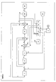
- FIG. 1 shows a flow scheme for an air driven ATR.
- temperatures and pressures are given at various stages of a process carried out in accordance with the present invention. However, it should be recognized that these temperatures and pressures are only illustrative of the anticipated conditions within the plant and actual values may vary for any particular process without departing from the present invention.
- a pressurized natural gas feedstock 1 is heated to 380°C by heat exchange against a shift converted gas stream (described below) and optionally against a superheated medium pressure (MP) steam stream (described below but not shown).
- a hydrogen stream 2 (described below) is added to the pressurized natural gas feedstock 1 and the resulting mixed stream 3 is preheated before being passed to a desulfurisation unit 4 comprising a hydrogenator (not shown) and a desulfuriser (not shown).
- a hydrogenator any organosulfur compounds (mercaptans) are converted to hydrogen sulfide by reduction with hydrogen over a hydrodesulfurisation catalyst.
- the hydrogen sulfide is then removed from the natural gas feedstock in the desulfuriser by absorption on a zinc oxide absorbent.
- a desulfurised natural gas feedstock 5 is withdrawn from the desulfurisation unit 4.
- Steam is introduced into the desulfurised natural gas feedstock 5 thereby generating a pre-reformer feed stream 8.
- the steam is taken as a medium pressure (MP) bleed from a steam turbine 6 and is introduced into the desulfurised hydrocarbon stream 5 via line 7.
- MP medium pressure
- the pre-reformer feed stream 8 is introduced to a pre-reformer 9 at a temperature of at least 560°C where at least a portion of the methane and of any C 2+ hydrocarbons contained in the natural gas feed are converted into hydrogen and carbon monoxide by reaction with steam over a pre-reforming catalyst.
- a pre-reformed (partially reformed) stream 10 exits the pre-reformer 9 at a temperature of 530°C and acts as a fuel feed stream for an autothermal reformer (ATR) 11.
- ATR autothermal reformer
- a heated compressed air stream 12 (optionally comprising up to 10 mole% steam, in particular, up to 1 mole % steam) is also fed to the ATR 11 to initiate the reforming of the fuel feed stream to synthesis gas (a mixture of essentially hydrogen, carbon monoxide, carbon dioxide and steam).
- synthesis gas a mixture of essentially hydrogen, carbon monoxide, carbon dioxide and steam.
- the feed rates of the fuel feed stream and the air feed stream are controlled such that the molar ratio of oxygen (O 2 ) contained in the air feed stream to carbon (in hydrocarbons) in the fuel feed stream is about 0.65:1.
- the air feed stream 12 is supplied from a compressor 13 and is heated by being passed through a heat recovery and steam generator (HRSG) 14 of a gas turbine 15 in heat exchange relationship with a post-fired exhaust gas 16.
- HRSG heat recovery and steam generator
- a synthesis gas stream 17 exits the ATR 11 and is cooled in a waste heat boiler (steam generator) 18 by heat exchange with a boiler feed water stream 19.
- the boiler feed water stream 19 is pre-heated by being passed through the heat recovery and steam generator 14 of the gas turbine 15 in heat exchange relationship with the post-fired exhaust gas 16 and is introduced to the waste heat boiler 18 at a temperature of 310°C with the pressure of the boiler feed water stream being sufficiently high that the boiler feed water is in a liquid state.
- High pressure steam is withdrawn from the waste heat boiler 18 at a temperature of 315°C and is passed via line 20 to the HRSG 14 where the high pressure steam is superheated to a temperature of 480°C by being passed through a heating coil of the HRSG 14 in heat exchange relationship with the post-fired exhaust gas from the gas turbine 15.
- the resulting superheated high pressure steam is passed via line 21 to a steam turbine 6 which drives an electrical generator 22.
- a cooled synthesis gas stream 23 exits the waste heat boiler and the remaining thermal energy in the cooled synthesis gas stream is used to preheat the pre-reformer feed stream 8, preferably, in heat exchanger 23a and to generate further HP steam (not shown).
- the cooled synthesis gas stream is then fed to a shift converter unit 24 comprising a high temperature shift reactor (not shown)and a low temperature shift reactor (not shown) where carbon monoxide is reacted with water to give carbon dioxide and hydrogen over a water gas shift catalyst.
- a partially shift converted gas stream exits the high temperature shift reactor and the thermal energy in the partially shift converted gas stream is used to generate more high pressure (HP) steam in a waste heat boiler (not shown) and to pre-heat boiler feed water (not shown).
- the cooled partially shift converted gas stream is then passed to the low temperature shift reactor.
- a shift converted gas stream 25 comprising hydrogen, steam, nitrogen and carbon dioxide is withdrawn from the low temperature shift reactor.
- the thermal energy associated with the shift converted gas stream is used to heat the natural gas feedstock 1 in heat exchanger 25a, the hydrogen stream that is fed to the gas turbine and optionally boiler feed water.
- the cooled shift converted gas stream is passed to a first condensate drum (not shown) where condensate separates from the shift converted gas stream.
- the shift converted gas stream is further cooled against one or more process streams such that further condensate condenses out of the shift converted gas stream, for example, the shift converted gas stream may be cooled against the reboiler duty of a CO 2 absorber-desorber unit.
- the cooled shift converted gas stream containing entrained condensate is then passed to a second condensate drum (not shown) where condensate separates from the shift converted gas stream.
- Condensate collected in the drums is fed to a condensate stripper where the condensate is stripped of volatile impurities (such as ammonia, hydrogen cyanide, methanol and carbon dioxide) with medium pressure (MP) steam.
- volatile impurities such as ammonia, hydrogen cyanide, methanol and carbon dioxide
- the vapour from the top of the stripper (comprising steam, and the volatile impurities) is introduced into the pre-reformer feed stream (not shown) to provide steam for the pre-reformer and also for the shift converter.
- a condensate stream having a reduced content of volatile impurities is withdrawn from the bottom of the condensate stripper and is passed to a condensate polishing unit (not shown) for removal of any remaining impurities, for example, formic acid.
- the condensate polishing unit provides demineralised water to the process of the present invention and also discharges excess water from the integrated reformer and power plant.
- the shift converted gas stream that is withdrawn from the top of the second condensate drum is then passed to a CO 2 removal unit 26 for example, a CO 2 absorber and desorber, which separates the stream into a concentrated carbon dioxide stream 27 and a hydrogen stream 28.
- a CO 2 removal unit 26 for example, a CO 2 absorber and desorber, which separates the stream into a concentrated carbon dioxide stream 27 and a hydrogen stream 28.
- the concentrated carbon dioxide stream 27 from the CO 2 removal unit 26 is then fed to a carbon dioxide compression and drying unit 29.
- the resulting pressurized and dehydrated concentrated carbon dioxide stream may be introduced to a pipeline that delivers the CO 2 to an injection well for enhanced recovery of hydrocarbons from a hydrocarbon-bearing formation via an associated production well (not shown).
- the hydrogen stream 28 from the CO 2 removal unit 26 is divided into three streams.
- a first hydrogen stream 2 is added to pressurized natural gas feedstock 1 (as described above).
- a second dry hydrogen stream is passed from the CO 2 removal unit 26 to a gas turbine 15 via line 30 where the second dry hydrogen stream undergoes combustion with air.
- the gas turbine 15 drives an electrical generator (not shown).
- a third dry hydrogen stream is passed from the CO 2 removal unit 26 to a post-firing burner of the HRSG 14 via line 31 for use as a post-firing fuel.
- the post-fired exhaust gas decreases in temperature as it passes through the HRSG 14 owing to heat exchange with the various process streams (for example, HP steam, boiler feed water and air feed to the ATR 11).
- the HRSG 14 may also be used to generate and superheat additional HP steam and to generate and superheat medium pressure MP and low pressure LP steam for use in the process of the present invention.
- the HRSG 14 may be used to reheat the exhaust steam (MP steam) from the first stage of the steam turbine 6.
Landscapes
- Chemical & Material Sciences (AREA)
- Chemical Kinetics & Catalysis (AREA)
- Organic Chemistry (AREA)
- Inorganic Chemistry (AREA)
- Health & Medical Sciences (AREA)
- General Health & Medical Sciences (AREA)
- Engineering & Computer Science (AREA)
- Combustion & Propulsion (AREA)
- Hydrogen, Water And Hydrids (AREA)
Priority Applications (11)
| Application Number | Priority Date | Filing Date | Title |
|---|---|---|---|
| EP06256419A EP1944268A1 (fr) | 2006-12-18 | 2006-12-18 | Processus |
| CA 2672164 CA2672164C (fr) | 2006-12-18 | 2007-11-29 | Procede de production de dioxyde de carbone et d'electricite a partir d'une charge d'hydrocarbures |
| CN200780051472A CN101687634A (zh) | 2006-12-18 | 2007-11-29 | 方法 |
| US12/448,303 US8567200B2 (en) | 2006-12-18 | 2007-11-29 | Process |
| PCT/GB2007/004575 WO2008074980A1 (fr) | 2006-12-18 | 2007-11-29 | Procédé |
| MX2009006525A MX2009006525A (es) | 2006-12-18 | 2007-11-29 | Procedimiento para la produccion de dioxido de carbono. |
| EA200900814A EA014913B1 (ru) | 2006-12-18 | 2007-11-29 | Способ производства диоксида углерода и электроэнергии из углеводородного сырья |
| AU2007336123A AU2007336123B2 (en) | 2006-12-18 | 2007-11-29 | Process |
| PL07824746T PL2102101T3 (pl) | 2006-12-18 | 2007-11-29 | Sposób wytwarzania ditlenku węgla i energii elektrycznej |
| EP07824746.7A EP2102101B1 (fr) | 2006-12-18 | 2007-11-29 | Procédé servant à produire de l'électricité et du dioxyde de carbone |
| NO20092537A NO20092537L (no) | 2006-12-18 | 2009-07-06 | Fremgangsmate for generering av elektrisk energi, damp og karbondioksid fra hydrokarbonramateriale |
Applications Claiming Priority (1)
| Application Number | Priority Date | Filing Date | Title |
|---|---|---|---|
| EP06256419A EP1944268A1 (fr) | 2006-12-18 | 2006-12-18 | Processus |
Publications (1)
| Publication Number | Publication Date |
|---|---|
| EP1944268A1 true EP1944268A1 (fr) | 2008-07-16 |
Family
ID=37963512
Family Applications (2)
| Application Number | Title | Priority Date | Filing Date |
|---|---|---|---|
| EP06256419A Ceased EP1944268A1 (fr) | 2006-12-18 | 2006-12-18 | Processus |
| EP07824746.7A Active EP2102101B1 (fr) | 2006-12-18 | 2007-11-29 | Procédé servant à produire de l'électricité et du dioxyde de carbone |
Family Applications After (1)
| Application Number | Title | Priority Date | Filing Date |
|---|---|---|---|
| EP07824746.7A Active EP2102101B1 (fr) | 2006-12-18 | 2007-11-29 | Procédé servant à produire de l'électricité et du dioxyde de carbone |
Country Status (10)
| Country | Link |
|---|---|
| US (1) | US8567200B2 (fr) |
| EP (2) | EP1944268A1 (fr) |
| CN (1) | CN101687634A (fr) |
| AU (1) | AU2007336123B2 (fr) |
| CA (1) | CA2672164C (fr) |
| EA (1) | EA014913B1 (fr) |
| MX (1) | MX2009006525A (fr) |
| NO (1) | NO20092537L (fr) |
| PL (1) | PL2102101T3 (fr) |
| WO (1) | WO2008074980A1 (fr) |
Cited By (3)
| Publication number | Priority date | Publication date | Assignee | Title |
|---|---|---|---|---|
| WO2010075591A3 (fr) * | 2008-12-24 | 2010-08-12 | Praxair Technology, Inc. | Procédé de réduction des émissions de dioxyde de carbone |
| EP2431328A4 (fr) * | 2009-04-03 | 2012-10-24 | Mitsubishi Heavy Ind Ltd | Appareil pour récupérer du co2 et procédé correspondant |
| EP4375235A3 (fr) * | 2022-08-10 | 2025-01-01 | Tallgrass MLP Operations, LLC | Intégration d'une turbine à gaz alimentée en hydrogène dans un procédé de reformage d'hydrocarbures |
Families Citing this family (113)
| Publication number | Priority date | Publication date | Assignee | Title |
|---|---|---|---|---|
| US7610692B2 (en) * | 2006-01-18 | 2009-11-03 | Earthrenew, Inc. | Systems for prevention of HAP emissions and for efficient drying/dehydration processes |
| US9605522B2 (en) | 2006-03-29 | 2017-03-28 | Pioneer Energy, Inc. | Apparatus and method for extracting petroleum from underground sites using reformed gases |
| AU2007353757B2 (en) * | 2007-05-17 | 2013-02-07 | Enero Inventions | Immediate response steam generating system and method |
| US8616294B2 (en) | 2007-05-20 | 2013-12-31 | Pioneer Energy, Inc. | Systems and methods for generating in-situ carbon dioxide driver gas for use in enhanced oil recovery |
| AU2009228062B2 (en) | 2008-03-28 | 2014-01-16 | Exxonmobil Upstream Research Company | Low emission power generation and hydrocarbon recovery systems and methods |
| WO2009120779A2 (fr) | 2008-03-28 | 2009-10-01 | Exxonmobil Upstream Research Company | Production d'électricité à faible émission et systèmes et procédés de récupération d'hydrocarbures |
| US7753972B2 (en) | 2008-08-17 | 2010-07-13 | Pioneer Energy, Inc | Portable apparatus for extracting low carbon petroleum and for generating low carbon electricity |
| EA026915B1 (ru) | 2008-10-14 | 2017-05-31 | Эксонмобил Апстрим Рисерч Компани | Способы и системы для регулирования продуктов горения |
| EP2233430A1 (fr) | 2009-03-24 | 2010-09-29 | Hydrogen Energy International Limited | Procédé de génération d'hydrogène et dioxyde de carbone |
| EP2233433A1 (fr) * | 2009-03-24 | 2010-09-29 | Hydrogen Energy International Limited | Procédé pour la génération d'électricité et pour la séquestration de dioxyde de carbone |
| EP2233432A1 (fr) | 2009-03-24 | 2010-09-29 | Hydrogen Energy International Limited | Installation pour génération d'électricité et pour la séquestration de dioxyde de carbone |
| JP5898069B2 (ja) | 2009-06-05 | 2016-04-06 | エクソンモービル アップストリーム リサーチ カンパニー | 燃焼器システムおよびその使用方法 |
| US7937948B2 (en) | 2009-09-23 | 2011-05-10 | Pioneer Energy, Inc. | Systems and methods for generating electricity from carbonaceous material with substantially no carbon dioxide emissions |
| CA2777768C (fr) | 2009-11-12 | 2016-06-07 | Exxonmobil Upstream Research Company | Systemes et procedes de recuperation d'hydrocarbure et de generation d'energie a faible taux d'emission |
| GB0922411D0 (en) | 2009-12-22 | 2010-02-03 | Johnson Matthey Plc | Conversion of hydrocarbons to carbon dioxide and electrical power |
| GB0922410D0 (en) | 2009-12-22 | 2010-02-03 | Johnson Matthey Plc | Conversion of hydrocarbons to carbon dioxide and electrical power |
| BR112012031153A2 (pt) | 2010-07-02 | 2016-11-08 | Exxonmobil Upstream Res Co | sistemas e métodos de geração de energia de triplo-ciclo de baixa emissão |
| TWI593878B (zh) | 2010-07-02 | 2017-08-01 | 艾克頌美孚上游研究公司 | 用於控制燃料燃燒之系統及方法 |
| CN102971508B (zh) | 2010-07-02 | 2016-06-01 | 埃克森美孚上游研究公司 | Co2分离系统和分离co2的方法 |
| EA029336B1 (ru) | 2010-07-02 | 2018-03-30 | Эксонмобил Апстрим Рисерч Компани | Системы и способ производства энергии путем стехиометрического сгорания с обогащенным воздухом и рециркуляцией отработавшего газа |
| US9732673B2 (en) | 2010-07-02 | 2017-08-15 | Exxonmobil Upstream Research Company | Stoichiometric combustion with exhaust gas recirculation and direct contact cooler |
| CN103096999A (zh) * | 2010-07-28 | 2013-05-08 | 萨加斯公司 | 碳捕集喷气发动机 |
| US9399950B2 (en) | 2010-08-06 | 2016-07-26 | Exxonmobil Upstream Research Company | Systems and methods for exhaust gas extraction |
| CN103069130B (zh) | 2010-08-06 | 2016-02-24 | 埃克森美孚上游研究公司 | 优化化学计量燃烧的系统和方法 |
| US20120227964A1 (en) * | 2011-03-07 | 2012-09-13 | Conocophillips Company | Carbon dioxide gas mixture processing with steam assisted oil recovery |
| TWI564474B (zh) | 2011-03-22 | 2017-01-01 | 艾克頌美孚上游研究公司 | 於渦輪系統中控制化學計量燃燒的整合系統和使用彼之產生動力的方法 |
| TWI593872B (zh) | 2011-03-22 | 2017-08-01 | 艾克頌美孚上游研究公司 | 整合系統及產生動力之方法 |
| TWI563166B (en) | 2011-03-22 | 2016-12-21 | Exxonmobil Upstream Res Co | Integrated generation systems and methods for generating power |
| TWI563165B (en) | 2011-03-22 | 2016-12-21 | Exxonmobil Upstream Res Co | Power generation system and method for generating power |
| US20130127163A1 (en) * | 2011-11-17 | 2013-05-23 | Air Products And Chemicals, Inc. | Decarbonized Fuel Generation |
| CN104428490B (zh) | 2011-12-20 | 2018-06-05 | 埃克森美孚上游研究公司 | 提高的煤层甲烷生产 |
| US9353682B2 (en) | 2012-04-12 | 2016-05-31 | General Electric Company | Methods, systems and apparatus relating to combustion turbine power plants with exhaust gas recirculation |
| EP2653209A1 (fr) * | 2012-04-18 | 2013-10-23 | Siemens Aktiengesellschaft | Dispositif de séparation du dioxyde de carbone et son procédé de fonctionnement ainsi qu'unité de séparation |
| US10273880B2 (en) | 2012-04-26 | 2019-04-30 | General Electric Company | System and method of recirculating exhaust gas for use in a plurality of flow paths in a gas turbine engine |
| US9784185B2 (en) | 2012-04-26 | 2017-10-10 | General Electric Company | System and method for cooling a gas turbine with an exhaust gas provided by the gas turbine |
| US9803865B2 (en) | 2012-12-28 | 2017-10-31 | General Electric Company | System and method for a turbine combustor |
| US9708977B2 (en) | 2012-12-28 | 2017-07-18 | General Electric Company | System and method for reheat in gas turbine with exhaust gas recirculation |
| US9599070B2 (en) | 2012-11-02 | 2017-03-21 | General Electric Company | System and method for oxidant compression in a stoichiometric exhaust gas recirculation gas turbine system |
| US9574496B2 (en) | 2012-12-28 | 2017-02-21 | General Electric Company | System and method for a turbine combustor |
| US9869279B2 (en) | 2012-11-02 | 2018-01-16 | General Electric Company | System and method for a multi-wall turbine combustor |
| US10161312B2 (en) | 2012-11-02 | 2018-12-25 | General Electric Company | System and method for diffusion combustion with fuel-diluent mixing in a stoichiometric exhaust gas recirculation gas turbine system |
| US9631815B2 (en) | 2012-12-28 | 2017-04-25 | General Electric Company | System and method for a turbine combustor |
| US10215412B2 (en) | 2012-11-02 | 2019-02-26 | General Electric Company | System and method for load control with diffusion combustion in a stoichiometric exhaust gas recirculation gas turbine system |
| US9611756B2 (en) | 2012-11-02 | 2017-04-04 | General Electric Company | System and method for protecting components in a gas turbine engine with exhaust gas recirculation |
| US10107495B2 (en) | 2012-11-02 | 2018-10-23 | General Electric Company | Gas turbine combustor control system for stoichiometric combustion in the presence of a diluent |
| US10208677B2 (en) | 2012-12-31 | 2019-02-19 | General Electric Company | Gas turbine load control system |
| US9581081B2 (en) | 2013-01-13 | 2017-02-28 | General Electric Company | System and method for protecting components in a gas turbine engine with exhaust gas recirculation |
| US9512759B2 (en) | 2013-02-06 | 2016-12-06 | General Electric Company | System and method for catalyst heat utilization for gas turbine with exhaust gas recirculation |
| US9938861B2 (en) | 2013-02-21 | 2018-04-10 | Exxonmobil Upstream Research Company | Fuel combusting method |
| TW201502356A (zh) | 2013-02-21 | 2015-01-16 | Exxonmobil Upstream Res Co | 氣渦輪機排氣中氧之減少 |
| WO2014133406A1 (fr) | 2013-02-28 | 2014-09-04 | General Electric Company | Système et procédé pour une chambre de combustion de turbine |
| US20140250945A1 (en) | 2013-03-08 | 2014-09-11 | Richard A. Huntington | Carbon Dioxide Recovery |
| CN105008499A (zh) | 2013-03-08 | 2015-10-28 | 埃克森美孚上游研究公司 | 发电和从甲烷水合物中回收甲烷 |
| TW201500635A (zh) | 2013-03-08 | 2015-01-01 | Exxonmobil Upstream Res Co | 處理廢氣以供用於提高油回收 |
| US9618261B2 (en) | 2013-03-08 | 2017-04-11 | Exxonmobil Upstream Research Company | Power generation and LNG production |
| EP2784288B1 (fr) * | 2013-03-28 | 2020-02-19 | Lumenion AG | Centrale électrique et procédé de génération d'énergie électrique |
| US9835089B2 (en) | 2013-06-28 | 2017-12-05 | General Electric Company | System and method for a fuel nozzle |
| US9631542B2 (en) | 2013-06-28 | 2017-04-25 | General Electric Company | System and method for exhausting combustion gases from gas turbine engines |
| TWI654368B (zh) | 2013-06-28 | 2019-03-21 | 美商艾克頌美孚上游研究公司 | 用於控制在廢氣再循環氣渦輪機系統中的廢氣流之系統、方法與媒體 |
| US9617914B2 (en) | 2013-06-28 | 2017-04-11 | General Electric Company | Systems and methods for monitoring gas turbine systems having exhaust gas recirculation |
| DE102013213528A1 (de) * | 2013-07-10 | 2015-01-15 | Siemens Aktiengesellschaft | Reformersystem zur Verbrennung von Restgas in einem Dampfreformer |
| US9587510B2 (en) | 2013-07-30 | 2017-03-07 | General Electric Company | System and method for a gas turbine engine sensor |
| US9903588B2 (en) | 2013-07-30 | 2018-02-27 | General Electric Company | System and method for barrier in passage of combustor of gas turbine engine with exhaust gas recirculation |
| US9951658B2 (en) | 2013-07-31 | 2018-04-24 | General Electric Company | System and method for an oxidant heating system |
| US20150075450A1 (en) * | 2013-09-13 | 2015-03-19 | Uop Llc | Heat recovery from a high pressure stream |
| US10030588B2 (en) | 2013-12-04 | 2018-07-24 | General Electric Company | Gas turbine combustor diagnostic system and method |
| US9752458B2 (en) | 2013-12-04 | 2017-09-05 | General Electric Company | System and method for a gas turbine engine |
| US10227920B2 (en) | 2014-01-15 | 2019-03-12 | General Electric Company | Gas turbine oxidant separation system |
| US9863267B2 (en) | 2014-01-21 | 2018-01-09 | General Electric Company | System and method of control for a gas turbine engine |
| US9915200B2 (en) | 2014-01-21 | 2018-03-13 | General Electric Company | System and method for controlling the combustion process in a gas turbine operating with exhaust gas recirculation |
| US10079564B2 (en) | 2014-01-27 | 2018-09-18 | General Electric Company | System and method for a stoichiometric exhaust gas recirculation gas turbine system |
| WO2015155256A1 (fr) * | 2014-04-08 | 2015-10-15 | Haldor Topsøe A/S | Procédé de chauffage d'un atr |
| US10047633B2 (en) | 2014-05-16 | 2018-08-14 | General Electric Company | Bearing housing |
| US9528055B2 (en) | 2014-06-28 | 2016-12-27 | Saudi Arabian Oil Company | Energy efficient gasification-based multi generation apparatus employing energy efficient acid gas removal plant-directed process schemes and related methods |
| US10060359B2 (en) | 2014-06-30 | 2018-08-28 | General Electric Company | Method and system for combustion control for gas turbine system with exhaust gas recirculation |
| US10655542B2 (en) | 2014-06-30 | 2020-05-19 | General Electric Company | Method and system for startup of gas turbine system drive trains with exhaust gas recirculation |
| US9885290B2 (en) | 2014-06-30 | 2018-02-06 | General Electric Company | Erosion suppression system and method in an exhaust gas recirculation gas turbine system |
| US9869247B2 (en) | 2014-12-31 | 2018-01-16 | General Electric Company | Systems and methods of estimating a combustion equivalence ratio in a gas turbine with exhaust gas recirculation |
| US9819292B2 (en) | 2014-12-31 | 2017-11-14 | General Electric Company | Systems and methods to respond to grid overfrequency events for a stoichiometric exhaust recirculation gas turbine |
| US10788212B2 (en) | 2015-01-12 | 2020-09-29 | General Electric Company | System and method for an oxidant passageway in a gas turbine system with exhaust gas recirculation |
| US10316746B2 (en) | 2015-02-04 | 2019-06-11 | General Electric Company | Turbine system with exhaust gas recirculation, separation and extraction |
| US10253690B2 (en) | 2015-02-04 | 2019-04-09 | General Electric Company | Turbine system with exhaust gas recirculation, separation and extraction |
| US10094566B2 (en) | 2015-02-04 | 2018-10-09 | General Electric Company | Systems and methods for high volumetric oxidant flow in gas turbine engine with exhaust gas recirculation |
| US10267270B2 (en) | 2015-02-06 | 2019-04-23 | General Electric Company | Systems and methods for carbon black production with a gas turbine engine having exhaust gas recirculation |
| JP6701778B2 (ja) * | 2015-02-13 | 2020-05-27 | 日本製鉄株式会社 | 炭化水素の改質による水素の製造方法、水素の製造装置、燃料電池の運転方法、及び燃料電池の運転装置 |
| US10145269B2 (en) | 2015-03-04 | 2018-12-04 | General Electric Company | System and method for cooling discharge flow |
| US10480792B2 (en) | 2015-03-06 | 2019-11-19 | General Electric Company | Fuel staging in a gas turbine engine |
| DE102015219398A1 (de) * | 2015-10-07 | 2017-04-13 | Siemens Aktiengesellschaft | Verfahren zum Betreiben eines Gas-und-Dampf-Kombinationskraftwerks sowie Gas-und-Dampf-Kombinationskraftwerk |
| RU2633972C1 (ru) * | 2016-04-25 | 2017-10-20 | Александр Васильевич Шаталов | Способ подачи топлива в камеру сгорания двигателя внутреннего сгорания |
| PL3269948T3 (pl) * | 2016-07-15 | 2022-07-18 | Carbon-Clean Technologies Gmbh | Sposób dostosowania mocy elektrowni z turbiną parową i elektrownia z turbiną parową |
| EP3333124B1 (fr) * | 2016-12-09 | 2019-06-26 | L'air Liquide, Société Anonyme Pour L'Étude Et L'exploitation Des Procédés Georges Claude | Installation et procédé de production de gaz de synthèse |
| US10155661B2 (en) * | 2017-01-27 | 2018-12-18 | L'air Liquide Societe Anonyme Pour L'etude Et L'exploitation Des Procedes Georges Claude | System and methods for improving natural gas usage in steam methane reformers |
| US10370248B2 (en) * | 2017-01-27 | 2019-08-06 | L'air Liquide Societe Anonyme Pour L'etude | Maximizing steam methane reformer combustion efficiency by pre-heating pre-reformed fuel gas |
| WO2019229722A1 (fr) | 2018-06-01 | 2019-12-05 | Avectas Limited | Plate-forme d'ingénierie cellulaire |
| KR20220020842A (ko) | 2019-06-13 | 2022-02-21 | 8 리버스 캐피탈, 엘엘씨 | 추가 생성물들의 공동 발생을 구비하는 동력 생산 |
| EP4045457A1 (fr) * | 2019-10-15 | 2022-08-24 | Topsoe A/S | Processus et installation d'hydrogène à reformage autothermique |
| US11661866B2 (en) * | 2020-01-30 | 2023-05-30 | Mitsubishi Power Americas, Inc. | Hydrogen and oxygen supplemental firing for combined cycle facility |
| CA3139301C (fr) * | 2020-03-13 | 2022-09-13 | Haldor Topsoe A/S | Procede et installation de production d'hydrocarbures a empreinte reduite de co2 et integration d'hydrogene amelioree |
| GB202009969D0 (en) * | 2020-06-30 | 2020-08-12 | Johnson Matthey Plc | Low-carbon hydrogen process |
| BR112023002917A2 (pt) * | 2020-08-17 | 2023-03-21 | Topsoe As | Processo e planta de hidrogênio baseado em atr |
| US11391204B2 (en) * | 2020-10-30 | 2022-07-19 | Doosan Heavy Industries & Construction Co., Ltd. | Hybrid power generation equipment |
| JP7572919B2 (ja) * | 2021-06-28 | 2024-10-24 | 株式会社日立製作所 | 蒸気ボイラシステム |
| US11753299B2 (en) * | 2021-08-20 | 2023-09-12 | Air Products And Chemicals, Inc. | Process for H2 and syngas production |
| EP4277875B1 (fr) | 2021-09-24 | 2025-08-06 | ExxonMobil Chemical Patents Inc. | Intégration de la production de gaz combustible riche en hydrogène avec une installation de production d'oléfines |
| ES3015566T3 (en) * | 2021-09-24 | 2025-05-06 | Exxonmobil Chemical Patents Inc | Production of hydrogen-rich fuel-gas with reduced coemission |
| FI4277874T3 (fi) * | 2021-09-24 | 2025-04-07 | Exxonmobil Chemical Patents Inc | Hiilivetyjen reformointiprosesseja, joihin liittyy akselienergian tuotantoa |
| US11512257B1 (en) * | 2021-09-24 | 2022-11-29 | Exxonmobil Chemical Patents Inc. | Integration of hydrogen-rich fuel-gas production with olefins production plant |
| US12097464B2 (en) * | 2021-09-24 | 2024-09-24 | Exxonmobil Chemical Patents Inc. | Amine CO2 separation process integrated with hydrocarbons processing |
| US11498834B1 (en) * | 2021-09-24 | 2022-11-15 | Exxonmobil Chemical Patents Inc. | Production of hydrogen-rich fuel-gas with reduced CO2 emission |
| US11479462B1 (en) * | 2021-09-24 | 2022-10-25 | Exxonmobil Chemical Patents Inc. | Hydrocarbon reforming processes with shaft power production |
| CN114352369B (zh) * | 2021-11-30 | 2023-03-14 | 上海慕帆动力科技有限公司 | 氨分解制氢的燃气轮机-汽轮机联合发电系统及控制方法 |
| US12565423B2 (en) | 2023-01-26 | 2026-03-03 | Valero Services, Inc. | Process for producing hydrogen from natural gas |
| GB202414609D0 (en) | 2024-10-04 | 2024-11-20 | Johnson Matthey Plc | Process for the production of hydrogen, carbon dioxide and power |
Citations (3)
| Publication number | Priority date | Publication date | Assignee | Title |
|---|---|---|---|---|
| WO2000003126A1 (fr) * | 1998-07-13 | 2000-01-20 | Norsk Hydro Asa | Procede de production d'energie electrique, de vapeur et de dioxyde de carbone a partir d'une charge d'hydrocarbure |
| US6830596B1 (en) * | 2000-06-29 | 2004-12-14 | Exxonmobil Research And Engineering Company | Electric power generation with heat exchanged membrane reactor (law 917) |
| US20050100490A1 (en) * | 2003-11-06 | 2005-05-12 | Burch Steven D. | Compact water vaporizer for dynamic steam generation and uniform temperature control |
Family Cites Families (42)
| Publication number | Priority date | Publication date | Assignee | Title |
|---|---|---|---|---|
| US3241933A (en) * | 1961-08-17 | 1966-03-22 | Conch Int Methane Ltd | Process for the reforming of natural gas |
| US3446747A (en) * | 1964-08-11 | 1969-05-27 | Chemical Construction Corp | Process and apparatus for reforming hydrocarbons |
| FR2045712B1 (fr) | 1969-06-25 | 1973-11-16 | Onia Gegi | |
| US3795485A (en) * | 1971-06-28 | 1974-03-05 | Fluor Corp | Synthesis gas generation apparatus |
| US4409196A (en) * | 1979-04-24 | 1983-10-11 | Foster Wheeler Energy Corporation | Synthesis gas for ammonia production |
| US4193259A (en) * | 1979-05-24 | 1980-03-18 | Texaco Inc. | Process for the generation of power from carbonaceous fuels with minimal atmospheric pollution |
| US4733528A (en) * | 1984-03-02 | 1988-03-29 | Imperial Chemical Industries Plc | Energy recovery |
| US4725380A (en) * | 1984-03-02 | 1988-02-16 | Imperial Chemical Industries Plc | Producing ammonia synthesis gas |
| EP0257493A1 (fr) | 1986-08-22 | 1988-03-02 | Air Products And Chemicals, Inc. | Séparation adsorptive de mélanges de gaz |
| GB2196016B (en) * | 1986-08-29 | 1991-05-15 | Humphreys & Glasgow Ltd | Clean electric power generation process |
| GB8629031D0 (en) | 1986-12-04 | 1987-01-14 | Shell Int Research | Producing hydrogen |
| GB8705275D0 (en) * | 1987-03-06 | 1987-04-08 | Foster Wheeler Energy Ltd | Production of fuel gas |
| DE3926964A1 (de) | 1989-08-16 | 1991-02-21 | Siemens Ag | Verfahren zur minderung des kohlendioxidgehalts des abgases eines gas- und dampfturbinenkraftwerks und danach arbeitendes kraftwerk |
| US5264202A (en) * | 1990-11-01 | 1993-11-23 | Air Products And Chemicals, Inc. | Combined prereformer and convective heat transfer reformer |
| GB9105095D0 (en) * | 1991-03-11 | 1991-04-24 | H & G Process Contracting | Improved clean power generation |
| US5769165A (en) * | 1996-01-31 | 1998-06-23 | Vastar Resources Inc. | Method for increasing methane recovery from a subterranean coal formation by injection of tail gas from a hydrocarbon synthesis process |
| US5733941A (en) * | 1996-02-13 | 1998-03-31 | Marathon Oil Company | Hydrocarbon gas conversion system and process for producing a synthetic hydrocarbon liquid |
| US6130259A (en) * | 1996-02-13 | 2000-10-10 | Marathon Oil Company | Hydrocarbon gas conversion system and process for producing a synthetic hydrocarbon liquid |
| US5861441A (en) * | 1996-02-13 | 1999-01-19 | Marathon Oil Company | Combusting a hydrocarbon gas to produce a reformed gas |
| AU714133B2 (en) | 1996-03-11 | 1999-12-16 | Reg Synthetic Fuels, Llc | Turbine-powered, Fischer-Tropsch system and method |
| MY118075A (en) | 1996-07-09 | 2004-08-30 | Syntroleum Corp | Process for converting gas to liquids |
| CN1211534A (zh) | 1997-06-09 | 1999-03-24 | 大同北产株式会社 | 气体发生装置及用它产生气体的方法 |
| NO319681B1 (no) | 1998-09-16 | 2005-09-05 | Statoil Asa | Fremgangsmate for fremstilling av en H2-rik gass og en CO2-rik gass ved hoyt trykk |
| NO317870B1 (no) | 1998-09-16 | 2004-12-27 | Statoil Asa | Fremgangsmate for a fremstille en H<N>2</N>-rik gass og en CO<N>2</N>-rik gass ved hoyt trykk |
| DK173897B1 (da) | 1998-09-25 | 2002-02-04 | Topsoe Haldor As | Fremgangsmåde til autotermisk reforming af et carbonhydridfødemateriale indeholdende højere carbonhydrider |
| KR20010100008A (ko) | 1999-02-03 | 2001-11-09 | 추후제출 | 암모니아 합성으로부터 퍼지 가스를 사용하는 방법 |
| CA2372179A1 (fr) | 1999-05-13 | 2000-11-23 | Shell Internationale Research Maatschappij B.V. | Procede d'hydrocraquage d'hydrocarbures pour la production d'hydrogene, d'hydrocarbures hydrocraques et d'electricite |
| US6314715B1 (en) | 1999-06-03 | 2001-11-13 | General Electric Co. | Modified fuel gas turbo-expander for oxygen blown gasifiers and related method |
| NO310863B1 (no) | 1999-11-19 | 2001-09-10 | Norske Stats Oljeselskap | Kogenerering av metanol og elektrisk kraft |
| GB0025552D0 (en) | 2000-10-18 | 2000-11-29 | Air Prod & Chem | Process and apparatus for the generation of power |
| US6531630B2 (en) * | 2000-12-29 | 2003-03-11 | Kenneth Ebenes Vidalin | Bimodal acetic acid manufacture |
| US6821501B2 (en) | 2001-03-05 | 2004-11-23 | Shell Oil Company | Integrated flameless distributed combustion/steam reforming membrane reactor for hydrogen production and use thereof in zero emissions hybrid power system |
| WO2003018958A1 (fr) | 2001-08-31 | 2003-03-06 | Statoil Asa | Procede et installation permettant une recuperation de petrole amelioree et une synthese simultanee d'hydrocarbures a partir de gaz naturel |
| JP4782423B2 (ja) | 2002-09-05 | 2011-09-28 | シエル・インターナシヨネイル・リサーチ・マーチヤツピイ・ベー・ウイ | 高純度水素の製造装置及び方法 |
| WO2004055322A1 (fr) | 2002-12-13 | 2004-07-01 | Statoil Asa | Procede de recuperation du petrole a partir d'un champ petrolifere |
| NO20026021D0 (no) | 2002-12-13 | 2002-12-13 | Statoil Asa I & K Ir Pat | Fremgangsmåte for ökt oljeutvinning |
| PL1601445T3 (pl) | 2003-03-10 | 2011-04-29 | Univ Texas | Sposób regeneracji roztworu wodnego z procesu absorpcji kwaśnego gazu poprzez wielostopniowe odparowywanie rzutowe i odpędzanie |
| NO20033230D0 (no) | 2003-07-16 | 2003-07-16 | Statoil Asa | Fremgangsmåte for utvinning og oppgradering av olje |
| US7183451B2 (en) * | 2003-09-23 | 2007-02-27 | Synfuels International, Inc. | Process for the conversion of natural gas to hydrocarbon liquids |
| US7083662B2 (en) | 2003-12-18 | 2006-08-01 | Air Products And Chemicals, Inc. | Generation of elevated pressure gas mixtures by absorption and stripping |
| EP1643100B1 (fr) * | 2004-09-29 | 2017-06-28 | Ansaldo Energia IP UK Limited | Centrale et méthode associée d'opération |
| US7467519B2 (en) * | 2005-08-09 | 2008-12-23 | Praxair Technology, Inc. | Electricity and synthesis gas generation method |
-
2006
- 2006-12-18 EP EP06256419A patent/EP1944268A1/fr not_active Ceased
-
2007
- 2007-11-29 WO PCT/GB2007/004575 patent/WO2008074980A1/fr not_active Ceased
- 2007-11-29 US US12/448,303 patent/US8567200B2/en not_active Expired - Fee Related
- 2007-11-29 AU AU2007336123A patent/AU2007336123B2/en not_active Ceased
- 2007-11-29 MX MX2009006525A patent/MX2009006525A/es active IP Right Grant
- 2007-11-29 EA EA200900814A patent/EA014913B1/ru not_active IP Right Cessation
- 2007-11-29 CN CN200780051472A patent/CN101687634A/zh active Pending
- 2007-11-29 CA CA 2672164 patent/CA2672164C/fr not_active Expired - Fee Related
- 2007-11-29 PL PL07824746T patent/PL2102101T3/pl unknown
- 2007-11-29 EP EP07824746.7A patent/EP2102101B1/fr active Active
-
2009
- 2009-07-06 NO NO20092537A patent/NO20092537L/no not_active Application Discontinuation
Patent Citations (3)
| Publication number | Priority date | Publication date | Assignee | Title |
|---|---|---|---|---|
| WO2000003126A1 (fr) * | 1998-07-13 | 2000-01-20 | Norsk Hydro Asa | Procede de production d'energie electrique, de vapeur et de dioxyde de carbone a partir d'une charge d'hydrocarbure |
| US6830596B1 (en) * | 2000-06-29 | 2004-12-14 | Exxonmobil Research And Engineering Company | Electric power generation with heat exchanged membrane reactor (law 917) |
| US20050100490A1 (en) * | 2003-11-06 | 2005-05-12 | Burch Steven D. | Compact water vaporizer for dynamic steam generation and uniform temperature control |
Cited By (7)
| Publication number | Priority date | Publication date | Assignee | Title |
|---|---|---|---|---|
| WO2010075591A3 (fr) * | 2008-12-24 | 2010-08-12 | Praxair Technology, Inc. | Procédé de réduction des émissions de dioxyde de carbone |
| US8007761B2 (en) | 2008-12-24 | 2011-08-30 | Praxair Technology, Inc. | Carbon dioxide emission reduction method |
| CN102333723A (zh) * | 2008-12-24 | 2012-01-25 | 普莱克斯技术有限公司 | 二氧化碳排放降低方法 |
| CN102333723B (zh) * | 2008-12-24 | 2013-12-25 | 普莱克斯技术有限公司 | 二氧化碳排放降低方法 |
| EP2431328A4 (fr) * | 2009-04-03 | 2012-10-24 | Mitsubishi Heavy Ind Ltd | Appareil pour récupérer du co2 et procédé correspondant |
| US9186619B2 (en) | 2009-04-03 | 2015-11-17 | Mitsubishi Heavy Industries, Ltd. | CO2 recovery unit and method therefor |
| EP4375235A3 (fr) * | 2022-08-10 | 2025-01-01 | Tallgrass MLP Operations, LLC | Intégration d'une turbine à gaz alimentée en hydrogène dans un procédé de reformage d'hydrocarbures |
Also Published As
| Publication number | Publication date |
|---|---|
| CA2672164C (fr) | 2015-03-31 |
| AU2007336123B2 (en) | 2012-06-21 |
| CA2672164A1 (fr) | 2008-06-26 |
| NO20092537L (no) | 2009-09-10 |
| US20100083666A1 (en) | 2010-04-08 |
| EP2102101B1 (fr) | 2013-07-24 |
| WO2008074980A1 (fr) | 2008-06-26 |
| EA014913B1 (ru) | 2011-02-28 |
| US8567200B2 (en) | 2013-10-29 |
| EA200900814A1 (ru) | 2009-12-30 |
| AU2007336123A1 (en) | 2008-06-26 |
| MX2009006525A (es) | 2009-09-04 |
| PL2102101T3 (pl) | 2014-01-31 |
| CN101687634A (zh) | 2010-03-31 |
| EP2102101A1 (fr) | 2009-09-23 |
Similar Documents
| Publication | Publication Date | Title |
|---|---|---|
| EP2102101B1 (fr) | Procédé servant à produire de l'électricité et du dioxyde de carbone | |
| EP2233433A1 (fr) | Procédé pour la génération d'électricité et pour la séquestration de dioxyde de carbone | |
| JP7802257B2 (ja) | 水素の生成のためのプロセス | |
| US9102534B2 (en) | Conversion of hydrocarbons to carbon dioxide and electrical power | |
| US9216903B2 (en) | Conversion of hydrocarbons to carbon dioxide and electrical power | |
| EP2233430A1 (fr) | Procédé de génération d'hydrogène et dioxyde de carbone | |
| KR20230029615A (ko) | 수소 생성 방법 | |
| EP2576433B1 (fr) | Génération de méthanol en utilisant de l'hydrogène haute pression ultra-pur | |
| EP2233432A1 (fr) | Installation pour génération d'électricité et pour la séquestration de dioxyde de carbone | |
| WO2023049570A1 (fr) | Production de gaz combustible riche en hydrogène avec réduction des émissions de co2 | |
| CN107539951A (zh) | 蒸汽重整天然气的方法,具有产生向该方法供应所需热量的热烟气的两个燃烧室 | |
| WO2026074262A1 (fr) | Procédé de production d'hydrogène, de dioxyde de carbone et d'énergie | |
| WO2025253086A1 (fr) | Procédé de production d'hydrogène | |
| AU2016273831A1 (en) | Generating methanol using ultrapure, high pressure hydrogen |
Legal Events
| Date | Code | Title | Description |
|---|---|---|---|
| PUAI | Public reference made under article 153(3) epc to a published international application that has entered the european phase |
Free format text: ORIGINAL CODE: 0009012 |
|
| AK | Designated contracting states |
Kind code of ref document: A1 Designated state(s): AT BE BG CH CY CZ DE DK EE ES FI FR GB GR HU IE IS IT LI LT LU LV MC NL PL PT RO SE SI SK TR |
|
| AX | Request for extension of the european patent |
Extension state: AL BA HR MK RS |
|
| STAA | Information on the status of an ep patent application or granted ep patent |
Free format text: STATUS: THE APPLICATION HAS BEEN REFUSED |
|
| 18R | Application refused |
Effective date: 20080822 |