EP1945372B1 - Abgabeeinheit mit verbesserter luftversorgung - Google Patents
Abgabeeinheit mit verbesserter luftversorgung Download PDFInfo
- Publication number
- EP1945372B1 EP1945372B1 EP06824254.4A EP06824254A EP1945372B1 EP 1945372 B1 EP1945372 B1 EP 1945372B1 EP 06824254 A EP06824254 A EP 06824254A EP 1945372 B1 EP1945372 B1 EP 1945372B1
- Authority
- EP
- European Patent Office
- Prior art keywords
- air
- dispenser unit
- liquid
- piston
- closing means
- Prior art date
- Legal status (The legal status is an assumption and is not a legal conclusion. Google has not performed a legal analysis and makes no representation as to the accuracy of the status listed.)
- Active
Links
Images

Classifications
-
- B—PERFORMING OPERATIONS; TRANSPORTING
- B05—SPRAYING OR ATOMISING IN GENERAL; APPLYING FLUENT MATERIALS TO SURFACES, IN GENERAL
- B05B—SPRAYING APPARATUS; ATOMISING APPARATUS; NOZZLES
- B05B11/00—Single-unit hand-held apparatus in which flow of contents is produced by the muscular force of the operator at the moment of use
- B05B11/01—Single-unit hand-held apparatus in which flow of contents is produced by the muscular force of the operator at the moment of use characterised by the means producing the flow
- B05B11/10—Pump arrangements for transferring the contents from the container to a pump chamber by a sucking effect and forcing the contents out through the dispensing nozzle
- B05B11/1087—Combination of liquid and air pumps
-
- B—PERFORMING OPERATIONS; TRANSPORTING
- B05—SPRAYING OR ATOMISING IN GENERAL; APPLYING FLUENT MATERIALS TO SURFACES, IN GENERAL
- B05B—SPRAYING APPARATUS; ATOMISING APPARATUS; NOZZLES
- B05B7/00—Spraying apparatus for discharge of liquids or other fluent materials from two or more sources, e.g. of liquid and air, of powder and gas
- B05B7/0018—Spraying apparatus for discharge of liquids or other fluent materials from two or more sources, e.g. of liquid and air, of powder and gas with devices for making foam
- B05B7/0025—Spraying apparatus for discharge of liquids or other fluent materials from two or more sources, e.g. of liquid and air, of powder and gas with devices for making foam with a compressed gas supply
Definitions
- the present invention relates to a dispenser unit particularly suitable for a liquid container, comprising an air pump with an air cylinder and an air piston axially displaceable in the air cylinder, an air space defined between the air cylinder and the air piston, supply-closing means for closing the air supply to the air pump, discharge- closing means for closing the air discharge from the air pump, an axially displaceable activating element for activating the air pump, and an air inlet opening in the activating element.
- Such a dispenser unit is known from for instance WO 2004/069418 .
- the dispenser unit shown herein is mounted on a liquid container by means of a threaded ring in order to obtain a foam pump.
- the activating element is formed by a cover with a spout-like dispensing part for dispensing foam.
- the activating element is movable relative to the liquid container. Product can be dispensed with the foam pump by pressing the activating element.
- a device comprising a pump for delivering a liquid with a foaming agent from a container is disclosed in US 5289952 .
- the displacement of a rigid push-button causes a variation in the volume of an annular chamber, and a return air inlet valve allows for the inflow of air into this chamber.
- the end of the container provided with the pump is closed by a head having a base recessed with respect to the end of a central sleeve carrying the pump and partly delimiting the said annular chamber, while the push-button has in its base a collar capable of closing the annular chamber and compressing the air contained therein.
- the object of the present invention is to provide an improved dispenser unit.
- the dispenser comprises for this purpose the feature that the air inlet opening debouches in the air space, and that at least a part of the air piston forms the supply- closing means.
- the functions of air piston and supply-closing means for the air pump are integrated into one structural component.
- said part of the air piston forms a moving part, in particular a moving part of a valve, of the supply-closing means, so that a separate valve part can be omitted.
- the part of the air piston forming the supply-closing means is preferably arranged against the inner wall of the activating element and over the air inlet opening.
- the inner wall of the activating element forms the seat for the air inlet valve.
- the air piston is advantageously movable in an axial direction for the purpose of forming the supply-closing means for air.
- the air inlet valve is opened or closed as a result of the axial movement the air piston performs.
- the air piston is preferably movable axially relative to the activating element. In this manner an actively controllable air inlet valve is obtained.
- the dispenser unit is further preferably provided with a liquid pump with a liquid cylinder and a liquid piston, wherein a liquid chamber is defined between the liquid cylinder and the liquid piston.
- the dispenser unit is further provided with an insert which is connected to the activating element and which comprises a mixing chamber for mixing air from the air pump and liquid from the liquid pump.
- the liquid piston of the dispenser unit can then be movable in axial direction relative to the activating element or be fixedly connected to the activating element.
- discharge-closing means for air are hereby formed.
- the insert preferably forms, together with the liquid piston axially movable relative thereto, the discharge-closing means for air.
- the discharge-closing means comprise in a determined embodiment a pressure-controlled air outlet valve.
- the discharge-closing means for air are formed by the activating element and the air piston.
- the air piston comprises a bottom edge part sealing the air cylinder, a top edge part sealing the air inlet opening, and a sleeve part extending substantially axially between the two edge parts.
- the activating element preferably comprises a cover with a spout-like dispensing part. The lower edge part of the cover can be displaced in axial direction over the inner wall of the air cylinder. The air and liquid pumps are operated during this displacement.
- the present invention relates to a dispensing assembly comprising a liquid container and a dispenser unit according to the invention connected thereto.
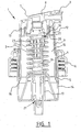
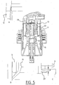
- Reference numeral 1 designates the cover which is provided with a spout-like dispensing part 2 and a casing 3.
- Casing 3 is provided on the underside with two peripheral edges 4, 5 with which it is in contact with the inner wall of a base part 6 of the dispenser unit.
- Base part 6 is provided with internal screw thread, by means of which the dispenser unit is screwed onto a liquid container.
- An annular support edge 7 with partition wall 8 is situated on the top side of cover 1.
- a cover member (not shown) can be arranged on support edge 7.
- a foam-forming element can also be arranged. This element is in contact with partition wall 8 and the product for dispensing passes through this element twice on the way to spout-like dispensing part 2.
- a cover member which forms an engaging surface for operating the dispenser unit is arranged on top of cover 1, over support edge 7 and partition wall 8.
- Reference numeral 9 designates an air piston which, according to the present invention, also serves as supply-closing means for closing the air-supplying air pump.
- reference numeral 10 in figure 1 designates an insert. Insert 10 is snapped onto an internal wall 11 of cover 1. Insert 10 comprises a mixing chamber 37 for mixing air from the air pump and liquid from the liquid pump.
- an air inlet opening 12 is arranged in casing 3 of cover 1. Air will enter the dispenser unit through this opening 12.
- the dispenser unit further comprises an air pump with an air cylinder 14 and an air piston 9 axially displaceable on air cylinder 14, an air space 15 defined between the air cylinder and the air piston, supply-closing means for closing the air supply to the air pump and discharge-closing means for closing the air discharge from the air pump.
- the supply-closing means for closing the air supply to the air pump is formed by the upper edge part 13 of air piston 9, which can co-act with the inner wall of cover 1. Air inlet opening 12 debouches into air space 15. On the opposite side the lower edge part 16 of the air piston is always in sealing contact with air cylinder 14. Air piston 9 can be moved axially relative to cover 1. The air supply to the air pump is closed by pressing in the cover, since the upper edge part 13 of the air piston comes into contact with the inner wall of cover 1. When the cover is pressed in further, air space 15 will be made smaller and the air accommodated therein will therefore be compressed.
- the dispenser unit is further provided with a liquid pump which comprises a liquid cylinder 17 and a liquid piston 18.
- a liquid chamber 19 is situated between liquid cylinder 17 and liquid piston 18.
- Reference numeral 20 designates the discharge-closing means for closing the liquid discharge from the liquid pump, while reference numeral 21 shows the supply-closing means for closing the liquid supply to the liquid pump.
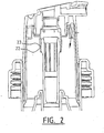
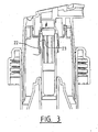
- Liquid piston 18 can be moved in axial direction relative to cover 1 for the purpose of forming the discharge-closing means for air.
- These discharge-closing means for air are formed between bottom edge part 22 of insert 10 and a peripheral rib 23 close to the top side of air piston 18.
- the discharge-closing means for closing the air discharge from the air pump are actively operated by pressing in cover 1, whereby the insert co-displaces axially in the first instance, and liquid piston 18 will remain stationary. Contact between bottom edge part 22 and peripheral rib 23 is hereby broken, and the compressed air can leave air chamber 15 on the way to mixing chamber 37 (see figure 3 ). As cover 1 is pressed further in, liquid piston 18 will also be co-displaced so that the liquid in liquid chamber 19 is compressed and carried to mixing chamber 37 via the discharge-closing means for closing liquid discharge 20.
- the above described preferred embodiment of the invention comprises an actively controllable air inlet valve mechanism and an actively controllable air outlet valve mechanism.
- Active is here understood to mean that the supply and discharge of air is controlled directly by displacement of one or more components of the dispenser unit.
- An actively controllable valve is also referred to as a "path-controlled” valve, wherein opening and closing takes place by displacing a component over a determined path or route. This in contrast a passively controlled or "pressure-controlled” valve, which is opened or closed as a result of a pressure difference.
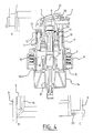
- the construction of the dispenser unit is largely the same, and essentially identical components, or at least components with substantially the same function, are therefore designated with the same reference numerals. It is otherwise noted that cover member 31 is shown in figures 4-6 . It can also be seen that the above mentioned foam-forming element 30 is passed through twice.
- the main difference from the embodiment shown in figures 1-3 is that here the liquid piston 18 is snapped fixedly into insert 10.
- the cover, the insert and the liquid piston therefore move axially up and downward as an assembly during operation.
- the discharge-closing means for closing the air discharge from the air pump are formed in this exemplary embodiment by a pressure-controlled pressure valve 40.
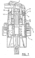
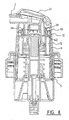
- FIGS 7 and 8 show a third embodiment of a dispenser unit according to the invention.
- This embodiment once again relates to a dispenser unit.
- the shown construction of the dispenser unit is largely the same as the second embodiment of the invention shown in figures 4-6 , and essentially identical components, or at least components with substantially the same function, are therefore designated with the same reference numerals.
- the liquid piston of the dispenser unit is also fixedly connected to the activating element in the third embodiment.
- the discharge-closing means for air from the air chamber comprise in the second embodiment a passively controlled (more specifically, a pressure-controlled) pressure valve 40, in the third preferred embodiment these discharge-closing means 39 are actively controllable.
- the third embodiment hereby provides a double-acting dispenser unit.
- Figure 7 shows the position in which there is a gap 41 between upper edge part 13 of air piston 9 and the inner wall of cover 1. Air can therefore flow into air chamber 15 via air inlet opening 12 and said gap 41, this being shown in figure 7 with an arrow.
- the upper edge part of air piston 9 comes to rest against the inner wall of cover 1 and thereby closes the air supply.
- This position is shown in figure 8 .
- This figure also shows that air from air chamber 15 enters mixing chamber 37 via an opening 38 created between air piston 9 and insert 10 and via slots or channels 42.
Landscapes
- Containers And Packaging Bodies Having A Special Means To Remove Contents (AREA)
- Closures For Containers (AREA)
- Compressors, Vaccum Pumps And Other Relevant Systems (AREA)
- Details Of Reciprocating Pumps (AREA)
- Reciprocating Pumps (AREA)
- Loading And Unloading Of Fuel Tanks Or Ships (AREA)
- Devices For Dispensing Beverages (AREA)
Claims (14)
- Abgabeeinheit, besonders geeignet für einen Flüssigkeitsbehälter, umfassend:- eine Luftpumpe mit einem Luftzylinder (14) und einem Luftkolben (9), der in dem Luftzylinder axial verschiebbar ist,- einen Luftraum (15), der zwischen dem Luftzylinder (14) und dem Luftkolben definiert ist,- Zufuhr-Schließmittel (13, 9) zum Schließen der Luftzufuhr zur Luftpumpe,- Abgabe-Schließmittel (18, 1) zum Schließen der Luftabgabe von der Luftpumpe,- ein axial verschiebbares Aktivierungselement zur Aktivierung der Luftpumpe, und- eine in dem Aktivierungselement angeordnete Lufteinlassöffnung (12), wobei die Lufteinlassöffnung in den Luftraum (15) mündet, dadurch gekennzeichnet, dass zumindest ein Abschnitt (13) des Luftkolbens (9) die Zufuhr-Schließmittel (13, 9) bildet und der Abschnitt gegen die Innenwand des Aktivierungselements und oberhalb der Lufteinlassöffnung angeordnet ist, wobei der Luftkolben relativ zu dem Aktivierungselement axial bewegbar ist.
- Abgabeeinheit nach Anspruch 1, wobei der Abschnitt des Luftkolbens einen beweglichen Abschnitt des Zufuhr-Schließmittels bildet.
- Abgabeeinheit nach Anspruch 1 oder 2, ferner umfassend eine Flüssigkeitspumpe mit einem Flüssigkeitszylinder (17) und einem Flüssigkeitskolben (18), wobei eine Flüssigkeitskammer (19) zwischen dem Flüssigkeitszylinder (17) und dem Flüssigkeitskolben (18) definiert ist.
- Abgabeeinheit nach Anspruch 3, ferner umfassend einen Einsatz (10), der mit dem Aktivierungselement (1) verbunden ist und der eine Mischkammer (37) aufweist zum Mischen von Luft von der Luftpumpe und Flüssigkeit von der Flüssigkeitspumpe.
- Abgabeeinheit nach Anspruch 3 oder 4, wobei der Flüssigkeitskolben (18) in axialer Richtung relativ zu dem Aktivierungselement bewegbar ist, um das Abgabe-Schließmittel für Luft auszubilden.
- Abgabeeinheit nach den Ansprüchen 4 und 5, wobei der Einsatz (10) zusammen mit dem Flüssigkeitskolben, der relativ zu diesem axial bewegbar ist, das Abgabe-Schließmittel für Luft ausbildet.
- Abgabeeinheit nach Anspruch 3 oder 4, wobei der Flüssigkeitskolben (18) mit dem Aktivierungselement verbunden ist.
- Abgabeeinheit nach Anspruch 7, wobei das Abgabe-Schließmittel ein druckgesteuertes Ventil (40) umfasst.
- Abgabeeinheit nach einem der Ansprüche 1 bis 8, wobei der Luftkolben einen Unterkantenabschnitt aufweist, der den Luftzylinder abdichtet, einen Oberkantenabschnitt, der die Lufteinlassöffnung abdichtet, und einen Hülsenabschnitt, der sich im Wesentlichen axial zwischen den zwei Kantenabschnitten erstreckt.
- Abgabeeinheit nach einem der Ansprüche 1 bis 9, wobei das Aktivierungselement eine Abdeckung (1) mit einem tüllenartigen Abgabeabschnitt (2) umfasst.
- Abgabeeinheit nach einem der vorhergehenden Ansprüche, wobei das Öffnen und Schließen der Luftzufuhr mit den Zufuhr-Schließmitteln und/oder der Luftabgabe mit den Abgabe-Schließmitteln in einer aktiv steuerbaren Weise durchgeführt wird.
- Abgabeeinheit nach einem der vorhergehenden Ansprüche, wobei die Zufuhr-Schließmittel und/oder die Abgabe-Schließmittel weggesteuerte Ventile umfassen.
- Abgabeanordnung mit einem Flüssigkeitsbehälter und einer damit verbundenen Abgabeeinheit nach einem der Ansprüche 1 bis 12.
- Verwendung einer Abgabeeinheit oder Abgabeanordnung nach einem der vorhergehenden Ansprüche.
Applications Claiming Priority (2)
| Application Number | Priority Date | Filing Date | Title |
|---|---|---|---|
| NL1030361A NL1030361C2 (nl) | 2005-11-07 | 2005-11-07 | Afgifte-eenheid met verbeterde luchttoevoer. |
| PCT/NL2006/000559 WO2007053017A1 (en) | 2005-11-07 | 2006-11-07 | Dispenser unit with improved air supply |
Publications (2)
| Publication Number | Publication Date |
|---|---|
| EP1945372A1 EP1945372A1 (de) | 2008-07-23 |
| EP1945372B1 true EP1945372B1 (de) | 2018-02-21 |
Family
ID=35967013
Family Applications (1)
| Application Number | Title | Priority Date | Filing Date |
|---|---|---|---|
| EP06824254.4A Active EP1945372B1 (de) | 2005-11-07 | 2006-11-07 | Abgabeeinheit mit verbesserter luftversorgung |
Country Status (11)
| Country | Link |
|---|---|
| US (1) | US8430273B2 (de) |
| EP (1) | EP1945372B1 (de) |
| JP (1) | JP4942758B2 (de) |
| KR (1) | KR101295973B1 (de) |
| CN (1) | CN101636233B (de) |
| AU (1) | AU2006309408B2 (de) |
| BR (1) | BRPI0618105A2 (de) |
| CA (1) | CA2628426A1 (de) |
| NL (1) | NL1030361C2 (de) |
| RU (1) | RU2429081C2 (de) |
| WO (1) | WO2007053017A1 (de) |
Families Citing this family (21)
| Publication number | Priority date | Publication date | Assignee | Title |
|---|---|---|---|---|
| US8499981B2 (en) * | 2008-02-08 | 2013-08-06 | Gojo Industries, Inc. | Bifurcated stem foam pump |
| GB2472235B (en) * | 2009-07-29 | 2011-07-06 | Brightwell Dispensers Ltd | Dispensing device with a disposable pump |
| JP5674138B2 (ja) * | 2011-01-31 | 2015-02-25 | 株式会社吉野工業所 | 泡吐出器 |
| CA2856732A1 (en) | 2011-12-09 | 2013-06-13 | Metavention, Inc. | Therapeutic neuromodulation of the hepatic system |
| US20150111918A1 (en) | 2012-03-08 | 2015-04-23 | Medtronic Ardian Luxembourg S.a.r.l | Immune system neuromodulation and associated systems and methods |
| US9204765B2 (en) * | 2012-08-23 | 2015-12-08 | Gojo Industries, Inc. | Off-axis inverted foam dispensers and refill units |
| US8678241B2 (en) * | 2012-08-27 | 2014-03-25 | Ya-Tsan Wang | Foam spray head assembly |
| GB2506182B (en) * | 2012-09-25 | 2018-05-30 | Derjin Hong Kong Holding Company Ltd | Lotion spray head assembly |
| US8955718B2 (en) * | 2012-10-31 | 2015-02-17 | Gojo Industries, Inc. | Foam pumps with lost motion and adjustable output foam pumps |
| CA2913346A1 (en) | 2013-06-05 | 2014-12-11 | Metavention, Inc. | Modulation of targeted nerve fibers |
| EP3226795B1 (de) | 2014-12-03 | 2020-08-26 | Metavention, Inc. | Systeme zur modulation von nerven oder anderem gewebe |
| NL2015724B1 (en) | 2015-11-04 | 2017-05-24 | Gab Eng & Dev B V | Storage holder for a dispenser. |
| GB201603949D0 (en) * | 2016-03-08 | 2016-04-20 | Rieke Packaging Systems Ltd | Foam dispensers |
| NL2016644B1 (en) | 2016-04-20 | 2017-11-07 | Gab Eng & Development B V | Storage holder for a dispenser |
| US10524859B2 (en) | 2016-06-07 | 2020-01-07 | Metavention, Inc. | Therapeutic tissue modulation devices and methods |
| KR102711288B1 (ko) | 2016-08-17 | 2024-09-27 | 삼성전자주식회사 | 결함 검사 방법 및 결함 검사 장치 |
| FR3096090B1 (fr) * | 2019-05-14 | 2022-10-28 | Aptar France Sas | Pompe à précompression haute pression |
| WO2021024027A1 (en) * | 2019-08-08 | 2021-02-11 | Kao Corporation | Foam dispenser, foam dispenser assembly and method for forming foam |
| CN114829018A (zh) | 2019-12-16 | 2022-07-29 | 宝洁公司 | 包括一体式分配喷嘴的液体分配系统 |
| USD980069S1 (en) | 2020-07-14 | 2023-03-07 | Ball Corporation | Metallic dispensing lid |
| US12168551B2 (en) | 2021-03-01 | 2024-12-17 | Ball Corporation | Metal container and end closure with seal |
Family Cites Families (20)
| Publication number | Priority date | Publication date | Assignee | Title |
|---|---|---|---|---|
| WO1992008657A1 (en) * | 1990-11-07 | 1992-05-29 | Daiwa Can Company | Bubble spouting pump vessel |
| RU2002517C1 (ru) * | 1991-03-28 | 1993-11-15 | Петр Васильевич Максимов | Беспропеллентный распылитель |
| FR2676010B1 (fr) * | 1991-04-30 | 1993-08-13 | Oreal | Dispositif pour la distribution de mousse, et bouton-poussoir pour un tel dispositif. |
| US5570819A (en) * | 1992-07-07 | 1996-11-05 | Daiwa Can Company | Foam dispensing pump container |
| JPH0669161U (ja) * | 1993-03-05 | 1994-09-27 | 大和製罐株式会社 | ポンプ式泡出し容器 |
| JP3596053B2 (ja) * | 1994-10-31 | 2004-12-02 | 東洋製罐株式会社 | 泡噴出ポンプ |
| NL1001366C2 (nl) * | 1995-10-06 | 1997-04-08 | Airspray Int Bv | Inrichting voor het afgeven van een luchtvloeistofmengsel, in het bijzonder schuim en daarvoor bestemde bedieningseenheid. |
| FR2748407B1 (fr) * | 1996-05-07 | 1998-08-28 | Valois | Dispositif de pulverisation du type biphasique pour un produit fluide ou pateux |
| FR2792553B1 (fr) * | 1999-04-22 | 2002-04-19 | Valois Sa | Dispositif de distribution biphasique |
| JP2002068256A (ja) * | 2000-08-29 | 2002-03-08 | Yoshino Kogyosho Co Ltd | 泡放出用ポンプ容器 |
| US6612468B2 (en) * | 2000-09-15 | 2003-09-02 | Rieke Corporation | Dispenser pumps |
| NL1016694C2 (nl) * | 2000-11-23 | 2002-05-24 | Keltub B V | Schuimvormingseenheid. |
| GB0208806D0 (en) * | 2002-04-17 | 2002-05-29 | Rieke Corp | Dispenser pumps |
| NL1022633C2 (nl) * | 2003-02-10 | 2004-08-12 | Keltub B V | Verbeterde schuimvormingseenheid. |
| DE10335842C5 (de) * | 2003-08-05 | 2011-04-28 | Seaquist Perfect Dispensing Gmbh | Abgabepackung |
| US6840408B1 (en) * | 2003-08-25 | 2005-01-11 | Continental Afa Dispensing Company | Air foam pump with shifting air piston |
| NL1024350C2 (nl) * | 2003-09-23 | 2005-03-24 | R & D Injector Ag | Afgifte-eenheid voor geconcentreerd injecteren. |
| US7048153B2 (en) * | 2003-09-25 | 2006-05-23 | Unilever Home & Personal Care Usa, Division Of Conopco, Inc. | Foam dispensing article |
| NL1030030C2 (nl) * | 2005-04-20 | 2006-10-23 | Keltec B V | Afgifte-eenheid met verbeterde toevoer-afsluitmiddelen. |
| CN100571893C (zh) * | 2005-04-20 | 2009-12-23 | Kel技术有限公司 | 带有改进供给关闭装置的分配器 |
-
2005
- 2005-11-07 NL NL1030361A patent/NL1030361C2/nl not_active IP Right Cessation
-
2006
- 2006-11-07 KR KR1020087013573A patent/KR101295973B1/ko not_active Expired - Fee Related
- 2006-11-07 RU RU2008122883/05A patent/RU2429081C2/ru not_active IP Right Cessation
- 2006-11-07 BR BRPI0618105-8A patent/BRPI0618105A2/pt not_active Application Discontinuation
- 2006-11-07 CN CN200680047683XA patent/CN101636233B/zh active Active
- 2006-11-07 CA CA002628426A patent/CA2628426A1/en not_active Abandoned
- 2006-11-07 US US12/092,039 patent/US8430273B2/en active Active
- 2006-11-07 JP JP2008539948A patent/JP4942758B2/ja not_active Expired - Fee Related
- 2006-11-07 EP EP06824254.4A patent/EP1945372B1/de active Active
- 2006-11-07 AU AU2006309408A patent/AU2006309408B2/en not_active Ceased
- 2006-11-07 WO PCT/NL2006/000559 patent/WO2007053017A1/en not_active Ceased
Also Published As
| Publication number | Publication date |
|---|---|
| CA2628426A1 (en) | 2007-05-10 |
| KR101295973B1 (ko) | 2013-08-13 |
| KR20080106889A (ko) | 2008-12-09 |
| CN101636233B (zh) | 2012-07-18 |
| AU2006309408A1 (en) | 2007-05-10 |
| EP1945372A1 (de) | 2008-07-23 |
| RU2008122883A (ru) | 2009-12-20 |
| AU2006309408B2 (en) | 2012-04-05 |
| US8430273B2 (en) | 2013-04-30 |
| JP4942758B2 (ja) | 2012-05-30 |
| BRPI0618105A2 (pt) | 2011-08-16 |
| RU2429081C2 (ru) | 2011-09-20 |
| CN101636233A (zh) | 2010-01-27 |
| JP2009515093A (ja) | 2009-04-09 |
| US20110168739A1 (en) | 2011-07-14 |
| WO2007053017A1 (en) | 2007-05-10 |
| NL1030361C2 (nl) | 2007-05-08 |
Similar Documents
| Publication | Publication Date | Title |
|---|---|---|
| EP1945372B1 (de) | Abgabeeinheit mit verbesserter luftversorgung | |
| RU2281811C2 (ru) | Пенообразующее устройство | |
| US9072412B2 (en) | Pull actuated foam pump | |
| CN101184557B (zh) | 分配装置 | |
| CN104411412B (zh) | 低残余倒置泵、分配器和再填充单元 | |
| EP1871538B1 (de) | Abgabevorrichtung mit verbessertem zufuhrschliessmittel | |
| EP2866948B1 (de) | Schaumspenderanordnung | |
| JP2009525845A (ja) | 自己浄化式泡吐出装置 | |
| JP2008531254A (ja) | 気液混合体を供給するための装置 | |
| JP6172805B2 (ja) | 泡吐出器 | |
| JP2004106885A (ja) | 発泡ポンプを備えた液体容器 | |
| RU2775420C2 (ru) | Устройство, система и способ дозирования жидкости из емкости | |
| KR100638070B1 (ko) | 수동 펌프 조립체 | |
| JP2006204989A (ja) | トリガー式液体噴出器 |
Legal Events
| Date | Code | Title | Description |
|---|---|---|---|
| PUAI | Public reference made under article 153(3) epc to a published international application that has entered the european phase |
Free format text: ORIGINAL CODE: 0009012 |
|
| 17P | Request for examination filed |
Effective date: 20080505 |
|
| AK | Designated contracting states |
Kind code of ref document: A1 Designated state(s): AT BE BG CH CY CZ DE DK EE ES FI FR GB GR HU IE IS IT LI LT LU LV MC NL PL PT RO SE SI SK TR |
|
| DAX | Request for extension of the european patent (deleted) | ||
| 17Q | First examination report despatched |
Effective date: 20161116 |
|
| RAP1 | Party data changed (applicant data changed or rights of an application transferred) |
Owner name: WESTROCK DISPENSING SYSTEMS R&D NETHERLANDS B.V. |
|
| GRAP | Despatch of communication of intention to grant a patent |
Free format text: ORIGINAL CODE: EPIDOSNIGR1 |
|
| INTG | Intention to grant announced |
Effective date: 20170901 |
|
| GRAS | Grant fee paid |
Free format text: ORIGINAL CODE: EPIDOSNIGR3 |
|
| GRAA | (expected) grant |
Free format text: ORIGINAL CODE: 0009210 |
|
| RAP1 | Party data changed (applicant data changed or rights of an application transferred) |
Owner name: SILGAN DISPENSING SYSTEMS NETHERLANDS B.V. |
|
| AK | Designated contracting states |
Kind code of ref document: B1 Designated state(s): AT BE BG CH CY CZ DE DK EE ES FI FR GB GR HU IE IS IT LI LT LU LV MC NL PL PT RO SE SI SK TR |
|
| REG | Reference to a national code |
Ref country code: GB Ref legal event code: FG4D |
|
| REG | Reference to a national code |
Ref country code: CH Ref legal event code: EP |
|
| REG | Reference to a national code |
Ref country code: AT Ref legal event code: REF Ref document number: 971133 Country of ref document: AT Kind code of ref document: T Effective date: 20180315 |
|
| REG | Reference to a national code |
Ref country code: IE Ref legal event code: FG4D |
|
| REG | Reference to a national code |
Ref country code: DE Ref legal event code: R096 Ref document number: 602006054763 Country of ref document: DE |
|
| REG | Reference to a national code |
Ref country code: NL Ref legal event code: MP Effective date: 20180221 |
|
| REG | Reference to a national code |
Ref country code: LT Ref legal event code: MG4D |
|
| REG | Reference to a national code |
Ref country code: AT Ref legal event code: MK05 Ref document number: 971133 Country of ref document: AT Kind code of ref document: T Effective date: 20180221 |
|
| PG25 | Lapsed in a contracting state [announced via postgrant information from national office to epo] |
Ref country code: CY Free format text: LAPSE BECAUSE OF FAILURE TO SUBMIT A TRANSLATION OF THE DESCRIPTION OR TO PAY THE FEE WITHIN THE PRESCRIBED TIME-LIMIT Effective date: 20180221 Ref country code: NL Free format text: LAPSE BECAUSE OF FAILURE TO SUBMIT A TRANSLATION OF THE DESCRIPTION OR TO PAY THE FEE WITHIN THE PRESCRIBED TIME-LIMIT Effective date: 20180221 Ref country code: LT Free format text: LAPSE BECAUSE OF FAILURE TO SUBMIT A TRANSLATION OF THE DESCRIPTION OR TO PAY THE FEE WITHIN THE PRESCRIBED TIME-LIMIT Effective date: 20180221 Ref country code: ES Free format text: LAPSE BECAUSE OF FAILURE TO SUBMIT A TRANSLATION OF THE DESCRIPTION OR TO PAY THE FEE WITHIN THE PRESCRIBED TIME-LIMIT Effective date: 20180221 Ref country code: FI Free format text: LAPSE BECAUSE OF FAILURE TO SUBMIT A TRANSLATION OF THE DESCRIPTION OR TO PAY THE FEE WITHIN THE PRESCRIBED TIME-LIMIT Effective date: 20180221 |
|
| PG25 | Lapsed in a contracting state [announced via postgrant information from national office to epo] |
Ref country code: BG Free format text: LAPSE BECAUSE OF FAILURE TO SUBMIT A TRANSLATION OF THE DESCRIPTION OR TO PAY THE FEE WITHIN THE PRESCRIBED TIME-LIMIT Effective date: 20180521 Ref country code: LV Free format text: LAPSE BECAUSE OF FAILURE TO SUBMIT A TRANSLATION OF THE DESCRIPTION OR TO PAY THE FEE WITHIN THE PRESCRIBED TIME-LIMIT Effective date: 20180221 Ref country code: SE Free format text: LAPSE BECAUSE OF FAILURE TO SUBMIT A TRANSLATION OF THE DESCRIPTION OR TO PAY THE FEE WITHIN THE PRESCRIBED TIME-LIMIT Effective date: 20180221 Ref country code: AT Free format text: LAPSE BECAUSE OF FAILURE TO SUBMIT A TRANSLATION OF THE DESCRIPTION OR TO PAY THE FEE WITHIN THE PRESCRIBED TIME-LIMIT Effective date: 20180221 Ref country code: GR Free format text: LAPSE BECAUSE OF FAILURE TO SUBMIT A TRANSLATION OF THE DESCRIPTION OR TO PAY THE FEE WITHIN THE PRESCRIBED TIME-LIMIT Effective date: 20180522 |
|
| PG25 | Lapsed in a contracting state [announced via postgrant information from national office to epo] |
Ref country code: EE Free format text: LAPSE BECAUSE OF FAILURE TO SUBMIT A TRANSLATION OF THE DESCRIPTION OR TO PAY THE FEE WITHIN THE PRESCRIBED TIME-LIMIT Effective date: 20180221 Ref country code: PL Free format text: LAPSE BECAUSE OF FAILURE TO SUBMIT A TRANSLATION OF THE DESCRIPTION OR TO PAY THE FEE WITHIN THE PRESCRIBED TIME-LIMIT Effective date: 20180221 Ref country code: RO Free format text: LAPSE BECAUSE OF FAILURE TO SUBMIT A TRANSLATION OF THE DESCRIPTION OR TO PAY THE FEE WITHIN THE PRESCRIBED TIME-LIMIT Effective date: 20180221 Ref country code: IT Free format text: LAPSE BECAUSE OF FAILURE TO SUBMIT A TRANSLATION OF THE DESCRIPTION OR TO PAY THE FEE WITHIN THE PRESCRIBED TIME-LIMIT Effective date: 20180221 |
|
| REG | Reference to a national code |
Ref country code: DE Ref legal event code: R097 Ref document number: 602006054763 Country of ref document: DE |
|
| PG25 | Lapsed in a contracting state [announced via postgrant information from national office to epo] |
Ref country code: DK Free format text: LAPSE BECAUSE OF FAILURE TO SUBMIT A TRANSLATION OF THE DESCRIPTION OR TO PAY THE FEE WITHIN THE PRESCRIBED TIME-LIMIT Effective date: 20180221 Ref country code: SK Free format text: LAPSE BECAUSE OF FAILURE TO SUBMIT A TRANSLATION OF THE DESCRIPTION OR TO PAY THE FEE WITHIN THE PRESCRIBED TIME-LIMIT Effective date: 20180221 Ref country code: CZ Free format text: LAPSE BECAUSE OF FAILURE TO SUBMIT A TRANSLATION OF THE DESCRIPTION OR TO PAY THE FEE WITHIN THE PRESCRIBED TIME-LIMIT Effective date: 20180221 |
|
| PLBE | No opposition filed within time limit |
Free format text: ORIGINAL CODE: 0009261 |
|
| STAA | Information on the status of an ep patent application or granted ep patent |
Free format text: STATUS: NO OPPOSITION FILED WITHIN TIME LIMIT |
|
| 26N | No opposition filed |
Effective date: 20181122 |
|
| PG25 | Lapsed in a contracting state [announced via postgrant information from national office to epo] |
Ref country code: SI Free format text: LAPSE BECAUSE OF FAILURE TO SUBMIT A TRANSLATION OF THE DESCRIPTION OR TO PAY THE FEE WITHIN THE PRESCRIBED TIME-LIMIT Effective date: 20180221 |
|
| REG | Reference to a national code |
Ref country code: DE Ref legal event code: R119 Ref document number: 602006054763 Country of ref document: DE |
|
| REG | Reference to a national code |
Ref country code: CH Ref legal event code: PL |
|
| PG25 | Lapsed in a contracting state [announced via postgrant information from national office to epo] |
Ref country code: MC Free format text: LAPSE BECAUSE OF FAILURE TO SUBMIT A TRANSLATION OF THE DESCRIPTION OR TO PAY THE FEE WITHIN THE PRESCRIBED TIME-LIMIT Effective date: 20180221 Ref country code: LU Free format text: LAPSE BECAUSE OF NON-PAYMENT OF DUE FEES Effective date: 20181107 |
|
| REG | Reference to a national code |
Ref country code: BE Ref legal event code: MM Effective date: 20181130 |
|
| REG | Reference to a national code |
Ref country code: IE Ref legal event code: MM4A |
|
| PG25 | Lapsed in a contracting state [announced via postgrant information from national office to epo] |
Ref country code: CH Free format text: LAPSE BECAUSE OF NON-PAYMENT OF DUE FEES Effective date: 20181130 Ref country code: LI Free format text: LAPSE BECAUSE OF NON-PAYMENT OF DUE FEES Effective date: 20181130 |
|
| PG25 | Lapsed in a contracting state [announced via postgrant information from national office to epo] |
Ref country code: FR Free format text: LAPSE BECAUSE OF NON-PAYMENT OF DUE FEES Effective date: 20181130 Ref country code: IE Free format text: LAPSE BECAUSE OF NON-PAYMENT OF DUE FEES Effective date: 20181107 Ref country code: DE Free format text: LAPSE BECAUSE OF NON-PAYMENT OF DUE FEES Effective date: 20190601 |
|
| PG25 | Lapsed in a contracting state [announced via postgrant information from national office to epo] |
Ref country code: BE Free format text: LAPSE BECAUSE OF NON-PAYMENT OF DUE FEES Effective date: 20181130 |
|
| PG25 | Lapsed in a contracting state [announced via postgrant information from national office to epo] |
Ref country code: TR Free format text: LAPSE BECAUSE OF FAILURE TO SUBMIT A TRANSLATION OF THE DESCRIPTION OR TO PAY THE FEE WITHIN THE PRESCRIBED TIME-LIMIT Effective date: 20180221 |
|
| PG25 | Lapsed in a contracting state [announced via postgrant information from national office to epo] |
Ref country code: PT Free format text: LAPSE BECAUSE OF FAILURE TO SUBMIT A TRANSLATION OF THE DESCRIPTION OR TO PAY THE FEE WITHIN THE PRESCRIBED TIME-LIMIT Effective date: 20180221 |
|
| PG25 | Lapsed in a contracting state [announced via postgrant information from national office to epo] |
Ref country code: HU Free format text: LAPSE BECAUSE OF FAILURE TO SUBMIT A TRANSLATION OF THE DESCRIPTION OR TO PAY THE FEE WITHIN THE PRESCRIBED TIME-LIMIT; INVALID AB INITIO Effective date: 20061107 |
|
| PG25 | Lapsed in a contracting state [announced via postgrant information from national office to epo] |
Ref country code: IS Free format text: LAPSE BECAUSE OF FAILURE TO SUBMIT A TRANSLATION OF THE DESCRIPTION OR TO PAY THE FEE WITHIN THE PRESCRIBED TIME-LIMIT Effective date: 20180621 |
|
| PGFP | Annual fee paid to national office [announced via postgrant information from national office to epo] |
Ref country code: GB Payment date: 20251127 Year of fee payment: 20 |