EP1945410B1 - Machine-outil - Google Patents
Machine-outil Download PDFInfo
- Publication number
- EP1945410B1 EP1945410B1 EP06807248A EP06807248A EP1945410B1 EP 1945410 B1 EP1945410 B1 EP 1945410B1 EP 06807248 A EP06807248 A EP 06807248A EP 06807248 A EP06807248 A EP 06807248A EP 1945410 B1 EP1945410 B1 EP 1945410B1
- Authority
- EP
- European Patent Office
- Prior art keywords
- distance
- control unit
- workpiece
- tool
- power tool
- Prior art date
- Legal status (The legal status is an assumption and is not a legal conclusion. Google has not performed a legal analysis and makes no representation as to the accuracy of the status listed.)
- Active
Links
Images
Classifications
-
- B—PERFORMING OPERATIONS; TRANSPORTING
- B25—HAND TOOLS; PORTABLE POWER-DRIVEN TOOLS; MANIPULATORS
- B25F—COMBINATION OR MULTI-PURPOSE TOOLS NOT OTHERWISE PROVIDED FOR; DETAILS OR COMPONENTS OF PORTABLE POWER-DRIVEN TOOLS NOT PARTICULARLY RELATED TO THE OPERATIONS PERFORMED AND NOT OTHERWISE PROVIDED FOR
- B25F5/00—Details or components of portable power-driven tools not particularly related to the operations performed and not otherwise provided for
- B25F5/003—Stops for limiting depth in rotary hand tools
-
- B—PERFORMING OPERATIONS; TRANSPORTING
- B23—MACHINE TOOLS; METAL-WORKING NOT OTHERWISE PROVIDED FOR
- B23B—TURNING; BORING
- B23B49/00—Measuring or gauging equipment on boring machines for positioning or guiding the drill; Devices for indicating failure of drills during boring; Centering devices for holes to be bored
- B23B49/003—Stops attached to drilling tools, tool holders or drilling machines
- B23B49/006—Attached to drilling machines
-
- B—PERFORMING OPERATIONS; TRANSPORTING
- B25—HAND TOOLS; PORTABLE POWER-DRIVEN TOOLS; MANIPULATORS
- B25B—TOOLS OR BENCH DEVICES NOT OTHERWISE PROVIDED FOR, FOR FASTENING, CONNECTING, DISENGAGING, OR HOLDING
- B25B23/00—Details of, or accessories for, spanners, wrenches, screwdrivers
- B25B23/0064—Means for adjusting screwing depth
-
- B—PERFORMING OPERATIONS; TRANSPORTING
- B25—HAND TOOLS; PORTABLE POWER-DRIVEN TOOLS; MANIPULATORS
- B25H—WORKSHOP EQUIPMENT, e.g. FOR MARKING-OUT WORK; STORAGE MEANS FOR WORKSHOPS
- B25H1/00—Work benches; Portable stands or supports for positioning portable tools or work to be operated on thereby
- B25H1/0021—Stands, supports or guiding devices for positioning portable tools or for securing them to the work
- B25H1/0078—Guiding devices for hand tools
- B25H1/0092—Guiding devices for hand tools by optical means
-
- B—PERFORMING OPERATIONS; TRANSPORTING
- B23—MACHINE TOOLS; METAL-WORKING NOT OTHERWISE PROVIDED FOR
- B23B—TURNING; BORING
- B23B2260/00—Details of constructional elements
- B23B2260/048—Devices to regulate the depth of cut
- B23B2260/0487—Depth indicators
-
- B—PERFORMING OPERATIONS; TRANSPORTING
- B23—MACHINE TOOLS; METAL-WORKING NOT OTHERWISE PROVIDED FOR
- B23B—TURNING; BORING
- B23B2260/00—Details of constructional elements
- B23B2260/092—Lasers
Definitions
- the invention relates to a hand tool according to the preamble of claim 1.
- a device for determining a penetration depth of a drill into a workpiece There are known drilling machines with a device for determining a penetration depth of a drill into a workpiece.
- a device for determining a penetration depth of a drill into a workpiece.
- Such a device is usually designed as a depth stop with a length scale.
- a distance of the power tool to the workpiece is determined.
- the depth stop is moved by a desired penetration depth and the workpiece is machined by retracting the drill to the desired penetration depth.
- an electric power tool such as a power drill
- a control device that allows inputs from a user to be passed to the throttle control, thus adapting the operation of the engine, such as the engine speed, to the individual's specifications.
- the Etektrotechnikmaschine the US 2005/103510 A Among other things, it also has a distance measuring sensor for determining the drilling depth or the drilling drive.
- a power tool in the form of a stand saw which has a machine tool monitoring device in the form of one or more radar sensors.
- the saw blade of the machine is braked or abruptly stopped by a corresponding control device.
- a hand tool in the form of a drill which has an electronic depth stop About a sensor for non-contact distance measurement, the drilling depth can be determined or the Bohrvortrieb be stopped according to a predetermined value.
- the machine has a control unit which regulates the drive of the machine depending on the distance measurement values.
- the invention relates to a hand tool with a control device comprising a control unit and a sensor unit for generating a distance signal.
- control unit is provided to control at least one operating parameter of a tool carrying unit as a function of the distance signal and to determine tool data as a function of the distance signal and to adapt the operating parameter to the tool data.
- the operating parameters can be adapted to a used tool, a material or to a processing line to achieve - especially automatically - a very good machining result, without the operator of the power tool would have special experience.
- the control can e.g. can be achieved by calculating the size of the operating parameter as a function of the distance signal or by selecting the size from a one-dimensional or multidimensional data field.
- the hand tool may be a saw, a grinder or an angle grinder.
- the drill can be designed with or without percussion, as a hammer drill, cordless drill or as a cordless screwdriver or the like. Also conceivable are a jigsaw, a saber saw, an angle grinder or a tile saw, in which an immersion depth should be adjustable in a workpiece.
- the sensor unit expediently comprises a distance sensor.
- the distance can be determined optically, eg by means of laser radiation and / or infrared radiation, by means of ultrasound or mechanically.
- the control unit is prepared for repeated, in particular continuous measurement of the distance during a work cycle.
- the operating parameter can be changed or adjusted during a work process.
- the operating parameter is advantageously a working parameter in which the tool support unit remains in motion and in particular the tool carried by the tool support unit is provided for machining a workpiece.
- the tool support unit may be a spindle for receiving a drill, bit or the like or a receptacle for a saw blade, a grinding wheel, a cutting wheel or the like.
- the operating parameter is at least one parameter from the group running speed, impact strength, beat frequency, pendulum stroke, maximum torque and direction.
- the operating parameter is a running speed, for example, the running speed of a tool can be reduced or reset to zero shortly before reaching a set machining depth or distance. Also conceivable is a disengagement of the tool, wherein a motor of the power tool continues to run and the tool, for example, comes to a standstill.
- the operating variable is a pendulum stroke, then, for example, the processing speed of a saw blade in the workpiece can be adapted to a desired processing speed and a quieter or more rapid work can be achieved.
- the operating parameter is a beat strength or beat frequency
- the impact strength or the beat frequency can be increased - for example, if a drill feed rate is recognized as insufficient.
- the operating variable is a maximum torque
- the torque can be - before or upon reaching a desired - especially in a screwdriver Screwing be reduced, so that a screwing over a screw in a workpiece is counteracted.
- the operating variable is a running direction.
- the control device can, in particular when using a known bit length, independently recognize whether an operator wants to screw in or out the screw and adjust the direction accordingly.
- control unit is provided for determining a relative speed of the sensor unit to a workpiece.
- the operating size can be adjusted so that an optimal work progress can be achieved.
- control unit is provided for changing the operating parameter while maintaining an operation on a workpiece in dependence on the distance signal.
- An insufficiently recognized or too rapid work progress can be optimized and the processing result thereby improved, without the operation would have to be interrupted.
- the control unit is provided to determine tool data as a function of the distance signal and to adapt the operating parameter to the tool data.
- a tool size eg a drill size or a saw size
- the determination can be made by a calculation or a selection of predetermined data.
- control unit is provided to determine material data from a workpiece reflecting the distance signal as a function of the distance signal and to adapt the operating parameter to the material data.
- the control unit determines material data from a workpiece reflecting the distance signal as a function of the distance signal and to adapt the operating parameter to the material data.
- the portable power tool can be produced particularly inexpensively if the sensor unit has an optical sensor, for example an infrared sensor.
- a distance to a workpiece can be determined by transit time measurement or by means of triangulation by a transmitter and a receiver of the sensor unit are arranged at a known distance from each other in the sensor unit.
- the distance signal is expediently a high-frequency signal, in particular a radar signal. Due to the high frequency, a distance sensor can be easily integrated into, for example, a drill and made small. For this purpose, the distance signal advantageously has a frequency above 70 GHz, whereby its antenna can turn out small. In addition, a distance sensor can be installed inside a machine housing and thus kept invisible and protected from contamination. Furthermore, a calibration and presetting can be omitted, so that the distance sensor is easy to use and störunan réelle.
- the Hand tool can be kept compact and insensitive, when the distance sensor is integrated on a Radarchip, which is provided for a high-frequency generation, a high-frequency reception and a raw signal processing. Additional processing in a low-frequency signal already on the Radarchip is also advantageous.
- a particularly safe operation of the power tool can be achieved if the control unit has safety data which relate to a distance of an object, in particular an operator, from a tool and are provided for controlling the operating parameter as a function of the distance signal and the safety data.
- the control unit may disable the movement of a tool when an operator comes too close to the tool, such as a circular saw.
- An additional brake can be used to counteract accidents.
- the operating parameter is expediently a movement parameter of the tool carrying unit.
- the sensor unit has a plurality of sensors and the control unit is provided for determining an angular position of a tool relative to a workpiece.
- Oblique drilling can be indicated, for example, by a warning signal and the operator can be facilitated straight drilling.
- an operating distance for example a drilling depth
- the reset can be done manually or automatically.
- an automatic reset for example, at the beginning of a machining operation, such as drilling, since it can be assumed that the tool, such as a drill, rests on the workpiece at the beginning of the machining process.
- Simple operation of the power tool can be achieved if the power tool includes an output unit, wherein the control unit is provided to display a working parameter by the output unit.
- the working parameter can be a set or achieved drilling depth or a set or traveled working distance.
- workpiece data e.g. workpiece data, a set or desired working mode, tool data and / or at least one operating parameter.
- a display can be made optically, e.g. alphanumeric or as a light signal, or as an acoustic signal.
- the handheld power tool comprises an operating unit for inputting a working parameter.
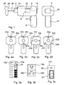
- FIG. 1 shows a executed as a drill 2 hand tool in a schematic representation of the side and from behind.
- the drilling machine 2 comprises a tool support unit in the form of a spindle 4, which is driven by a motor 6, a handle 8 with an operating knob 10 and a control unit 12 for controlling the motor 6, with a sensor unit 14 and a display means 16 as output unit with a liquid crystal display connected is.
- a tool 18 is attached in the form of a drill.
- FIG. 1 The principle shown is at least substantially transferable to all hand tool machines shown in the figures.
- FIGS. 2a-2d Four different hand tool machines designed as drills 20a-20d are shown in a schematic front view.
- the drilling machines 20a-20d each include a sensor unit 22a-22d each having one or more sensors 24a-24h.
- the drilling machine 20a comprises only a sensor 24a for measuring a distance 26 between the sensor 24a and a workpiece 28.
- two sensors 24b, 24c and 24d, 24e as in the drilling machine 20b in FIG. 2b or 20c in Figure 2c
- tilting of the drill 20b, 20c in or transverse to a handle direction relative to the workpiece 28 can be detected by a different distance of the sensors 24b, 24c or 24d, 24e from the workpiece 28.
- three sensors 24f - 24h as in Figure 2d or more sensors, a tilting of the drilling machine 20 d can be detected longitudinally and transversely to the handle direction and an operator an exactly perpendicular drilling into the workpiece 28 can be facilitated.
- FIGS. 3a and 3b show two different display means 16a, 16b for use in an arrangement, such as in FIG. 1 is shown.
- the display means 16a indicates a distance 26 from, for example, the sensor unit 14 to the workpiece 28 or a distance change based on seven LEDs 32, which light up or not depending on the distance 26 or distance change.
- an operating unit for example in the form of a button 34 a
- the display means 16a reset to zero, for example, when a tip of the tool 18 abuts the workpiece 28.
- the distance traveled by the position of the resetting of the indicating means 16a of the sensor unit 14 relative to the workpiece 28 is displayed in 1 cm increments.
- the distance display is numeric in increments of 0.1 cm.
- the display means 16b comprises two buttons 34b, c. Upon simultaneous depression of the two buttons 34b, c, the distance indication is zeroed.
- the buttons 34b, c are used separately until the desired drilling depth is displayed. Subsequently, the tool 18 can be applied to the workpiece 28 and the operating knob 10 can be moved so that the motor 6 starts and moves the tool 18.
- the display means 16b is automatically zeroed by the control unit 12 and displayed by the tool 18 in the workpiece 28 covered working distance.
- the motor 6 is automatically switched off by the control unit 12.
- disengaging the spindle 4 to an idle or audible signal or visual indication on the display means 16b is possible, for example by the displayed number starting to flash.
- the display means 16c off Figure 3c has a rotary control 37 and an LED 32.
- distances 26 are printed and can be easily adjusted. Upon reaching At the distance 26 the LED 32 lights up or the motor 6 is switched off.
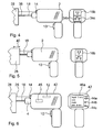
- FIG. 4 An alternative method for presetting a drilling depth is described below with reference to FIGS. 4 and 5 explained.
- a dowel 38 To the workpiece 28, for example a wall, is a dowel 38, as in FIG. 4 shown, created. Now the tool 18 is applied to the dowel 38 and the two buttons 34b, 34c are pressed simultaneously, thereby nullifying the display means 16b, as in FIG. 4 is shown.
- the control unit 12 comprises a distance data memory, wherein the simultaneous pressing of the buttons 34b, 34c resets the data in the distance data memory.
- the dowel 38 is removed and the tool 18, as in FIG. 5 shown, applied directly to the workpiece 28.
- the sensor unit 14 is thereby brought closer to the workpiece 28 by the length of the dowel 38, for example by 5.5 cm.
- This change in distance is indicated on the display means 16b.
- the operation button 10 can be pressed, whereby the display means 16b is zeroed and the tool 18 is inserted into the workpiece 28.
- the preset value of, for example, 5.5 cm corresponds to a drilling depth 40 exactly the length of the plug 38.
- the operation is interrupted or the achievement of the target work acoustically or visually displayed.
- FIG. 6 shows a further executed as a drill 42 hand tool.
- Substantially identical components are basically numbered with the same reference numerals.
- the drilling machine 42 may be operated in a number of modes that are selectable by means of a knob 44a adjustment means.
- the selected mode is displayed on a display means 46a, in FIG. 6 an automatic mode is indicated by the display "auto".
- buttons 44b, 44c a desired drilling depth can be set, which is also displayed on the display means 46a. Alternatively this is to the FIGS.
- the sensor unit 14 comprises a high-frequency transmitter, for example a radar transmitter.
- the radar transmitter is part of a compact component in the form of a radar chip, on which evaluation electronics are integrated. From the distance 26 is automatically closed by the control unit 12 on the type of tool 18, namely its thickness. The inference takes place in the control unit 12 on the basis of a data field in which drill bits are assigned drill lengths.
- the drill length can be determined from the distance 26 and a known position of a stop for the tool 18 within the spindle 4.
- the drill thickness is now also displayed on the display means 46a, in the example FIG. 6 it is 8 mm.
- the drill thickness can be determined by means of an additional, for example, arranged in the drill chuck sensor.
- the from the Workpiece 28 reflected distance signal is received by the sensor unit 14 and examined for its phase in relation to the distance 26. From this ratio, the control unit detects a phase jump of the distance signal in the workpiece 28 and closes it on the material of the workpiece 28, for example metal.
- the determination result is also displayed on the display means 46a.
- the control unit 12 calculates an optimal drilling mode, wherein the calculation includes the material of the workpiece 28 and the drill bit thickness.
- an optimal speed is given as an operating parameter, with which the spindle 4 and thus the tool 18 is driven by the motor 6.
- a maximum torque is specified as a further operating parameter above which a safety clutch 48 disengages and interrupts the power transmission from the motor 6 to the spindle 4. In this way, a cancellation of the tool 18 can be prevented.
- the operating parameters may also be displayed on the display means 46a, for example as additional information or as separately retrievable information, e.g. by an operation of the button 44a.
- the drilling progress of the tool 18 in the workpiece 28 is indicated by a retrograde indication of the drilling depth on the display means 46a, so that an operator always knows which way to remain to drill.
- the tool 18 Upon reaching the desired drilling depth, the tool 18 is disengaged by the safety clutch 48 and the motor 6 is slowly stopped by the control unit 12.
- an impact strength and / or impact frequency of the control unit 12 is adapted to the tool 18 as an additional operating parameter.
- the speed of the drilling progress ie how fast the drill penetrates into the workpiece 28, is detected by the control unit and the impact strength possibly changed, increased with slow drilling progress and lowered at very fast drilling progress, for example in bricks.
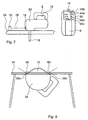
- FIG. 7 shows a jigsaw 50 in a perspective view from the side and from above.
- the jigsaw 50 comprises a tool 18 embodied as a jigsaw blade, a handle 8, a sensor unit 14 and associated control elements, as described in relation to the preceding figures.
- an operation mode can be set by the knob 44a, in FIG. 7 it is an automatic mode.
- a desired working speed, slow, medium or fast can be selected by means of the button 44b. This speed is also displayed on the display means 46b.
- the button 44c the material of the workpiece to be machined 28 can be selected. Alternatively, the material is automatically determined from the distance signal.
- the distance 26 from the sensor unit 14 to a measuring element 52, which an operator has connected to the workpiece 28, is permanently measured and from this an operating speed of the tool 18 in the workpiece 28 is determined.
- the design of the sensor unit 14 as Doppler radar for direct determination of the work progress of the tool 18 in the workpiece 28. From the work progress, the workpiece material and the desired work progress is determined by the control unit 12, an optimal pendulum stroke and the tool 18 is controlled accordingly, thereby a good work result, such as a clean cut in the workpiece 28, can be achieved.
- FIG. 8 shows a designed as a circular saw 54 hand tool, which is attached to a workbench 56 and is used as a table saw.
- the circular saw 54 includes two sensors 58a, 58b each having a in FIG. 8 If any object within the monitoring area 60 is moved at a speed exceeding a safety value stored in the control unit 12 of the portable circular saw 54, the tool 18, which is a circular saw blade, is immediately stopped by means of a brake. If an object with a speed exceeding a second safety value of the control unit 12 is removed from the tool 18, the tool 18 is also immediately stopped.
- the second safety value is in this case substantially larger than the first safety value, so that the circular saw blade continues to run at a speedy lead away a workpiece, but abruptly stops, for example, in a back of a hand of an operator.
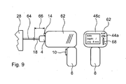
- FIG. 9 shows a cordless screwdriver 62 in a schematic representation of the side and from behind.
- a tool 18 is attached in the form of a screw.
- an operating mode of the cordless screwdriver 62 can first be made with the aid of the button 44a of a display means 46c be selected, for example, the automatic mode, as shown in Figure 9.
- a rotary knob 68 can now be determined how deep the screw 64 is to be screwed into the workpiece 28.
- the displayed depth is displayed on the display means 46c, and the screw 64 can - analogous to FIG. 6 described - are screwed into the workpiece 28 in the desired depth of engagement.
- the distance that the screw 64 should protrude from the workpiece 28 is set; in FIG. 9, 8 mm are indicated.
- the tool 18 is inserted, for example, in a provided with a screw slot gauge and the actuator button 10 is pressed briefly.
- the control unit now calculates in conjunction with the sensor unit 14 the distance 26 to the gauge, which corresponds to a distance 66 to the head of the screw 64.
- the screw 64 can be screwed into the workpiece 28, wherein the distance 26 between the sensor unit 14 and workpiece 28 is permanently monitored. If this distance 26 reaches the distance 66 plus the set distance of 8 mm, the spindle 4 is automatically decoupled from the control unit 12 and the motor 6 is brought to a standstill.
- the control unit 12 recognizes by means of the distance 26 the slight protrusion of the screw 64 from the workpiece 28 and automatically determines the direction of rotation of the screw bit so that the screw 64 upon depression of the actuating button 10th is unscrewed. In this way, the direction of rotation of the screw is automatically adjusted by the control unit 12 depending on the distance signal.
Landscapes
- Engineering & Computer Science (AREA)
- Mechanical Engineering (AREA)
- Drilling And Boring (AREA)
- Numerical Control (AREA)
- Sawing (AREA)
Claims (10)
- Machine-outil à main comprenant un dispositif de commande comprenant une unité de commande (12) et une unité de capteur (14), pour produire un signal d'éloignement, l'unité de commande (12) étant prévue pour commander au moins un paramètre de fonctionnement d'une unité porte-outil en fonction du signal d'éloignement, caractérisée en ce que l'unité de commande (12) est prévue pour déterminer des données de matériau en fonction du signal d'éloignement et pour adapter le paramètre de fonctionnement aux données de matériau.
- Machine-outil à main selon la revendication 1, caractérisée en ce que le paramètre de fonctionnement est au moins un paramètre parmi le groupe constitué par la vitesse d'avance, la force d'impact, la fréquence d'impact, la course pendulaire, le couple maximal et la direction d'avance.
- Machine-outil à main selon la revendication 1 ou 2, caractérisée en ce que l'unité de commande (12) est prévue pour modifier le paramètre de fonctionnement en conservant une passe de travail sur une pièce (28), en fonction du signal d'éloignement.
- Machine-outil à main selon l'une quelconque des revendications précédentes, caractérisée en ce que l'unité de commande (12) est prévue pour déterminer, en fonction du signal d'éloignement, des données de matériau d'une pièce (28) réfléchissant le signal d'éloignement, et pour adapter le paramètre de fonctionnement aux données de matériau.
- Machine-outil à main selon l'une quelconque des revendications précédentes, caractérisée en ce que le signal d'éloignement est un signal haute fréquence, notamment un signal radar.
- Machine-outil à main selon l'une quelconque des revendications précédentes, caractérisée en ce que l'unité de commande (12) présente des données de sécurité, qui concernent une distance d'un objet, notamment d'un opérateur, à un outil (18), et qui sont prévues pour commander le paramètre de fonctionnement en fonction du signal d'éloignement et des données de sécurité.
- Machine-outil à main selon l'une quelconque des revendications précédentes, caractérisée en ce que l'unité de capteur (14) présente plusieurs capteurs (24a-h) et l'unité de commande (12) est prévue pour déterminer une position angulaire d'un outil (18) par rapport à une pièce (28).
- Machine-outil à main selon l'une quelconque des revendications précédentes, caractérisée par une mémoire de données d'éloignement et un moyen pour remettre à zéro des données dans la mémoire de données d'éloignement.
- Machine-outil à main selon l'une quelconque des revendications précédentes, caractérisée par une unité de sortie, l'unité de commande étant prévue pour indiquer un paramètre de travail par le biais de l'unité de sortie.
- Machine-outil à main selon l'une quelconque des revendications précédentes, caractérisée par une unité de contrôle pour entrer un paramètre de travail.
Applications Claiming Priority (2)
| Application Number | Priority Date | Filing Date | Title |
|---|---|---|---|
| DE102005049130A DE102005049130A1 (de) | 2005-10-14 | 2005-10-14 | Handwerkzeugmaschine |
| PCT/EP2006/067384 WO2007042569A1 (fr) | 2005-10-14 | 2006-10-13 | Machine-outil |
Publications (2)
| Publication Number | Publication Date |
|---|---|
| EP1945410A1 EP1945410A1 (fr) | 2008-07-23 |
| EP1945410B1 true EP1945410B1 (fr) | 2011-03-16 |
Family
ID=37478914
Family Applications (1)
| Application Number | Title | Priority Date | Filing Date |
|---|---|---|---|
| EP06807248A Active EP1945410B1 (fr) | 2005-10-14 | 2006-10-13 | Machine-outil |
Country Status (7)
| Country | Link |
|---|---|
| US (1) | US20080196911A1 (fr) |
| EP (1) | EP1945410B1 (fr) |
| CN (1) | CN101287578A (fr) |
| AT (1) | ATE501814T1 (fr) |
| DE (2) | DE102005049130A1 (fr) |
| RU (1) | RU2008118494A (fr) |
| WO (1) | WO2007042569A1 (fr) |
Cited By (2)
| Publication number | Priority date | Publication date | Assignee | Title |
|---|---|---|---|---|
| DE202019106209U1 (de) | 2018-10-12 | 2019-11-20 | Fischerwerke Gmbh & Co. Kg | Motorisch drehend angetriebenes Handwerkzeug |
| DE202018006290U1 (de) | 2018-10-12 | 2019-11-29 | Fischerwerke Gmbh & Co. Kg | Motorisch drehend angetriebenes Handwerkzeug |
Families Citing this family (59)
| Publication number | Priority date | Publication date | Assignee | Title |
|---|---|---|---|---|
| DE102006007990A1 (de) * | 2006-02-21 | 2007-08-30 | Robert Bosch Gmbh | Handwerkzeugmaschine |
| US20090038456A1 (en) * | 2007-07-23 | 2009-02-12 | Wade Burch | Cut Finish Actuator For Table Saw |
| US11999516B2 (en) | 2008-04-23 | 2024-06-04 | Signode Industrial Group Llc | Strapping device |
| US10518914B2 (en) | 2008-04-23 | 2019-12-31 | Signode Industrial Group Llc | Strapping device |
| DE102008001774A1 (de) * | 2008-05-14 | 2009-11-19 | Robert Bosch Gmbh | Verfahren zum Betrieb einer Werkzeugmaschine, insbesondere einer Handwerkzeugmaschine |
| US8454619B1 (en) * | 2008-12-10 | 2013-06-04 | William C. Head | Prosthetic socket alignment |
| US8469962B1 (en) | 2008-12-10 | 2013-06-25 | William C. Head | Prosthetic socket alignment |
| CN102753782B (zh) * | 2010-01-07 | 2015-09-30 | 布莱克和戴克公司 | 具有旋转输入控制的电动螺丝起子 |
| US9266178B2 (en) | 2010-01-07 | 2016-02-23 | Black & Decker Inc. | Power tool having rotary input control |
| US8875804B2 (en) | 2010-01-07 | 2014-11-04 | Black & Decker Inc. | Screwdriving tool having a driving tool with a removable contact trip assembly |
| DE102010007714B3 (de) * | 2010-02-12 | 2011-06-01 | Festool Gmbh | Hand-Werkzeugmaschine mit einem Positionserfassungsmittel für ihre Werkzeugaufnahme |
| TWM386950U (en) * | 2010-04-09 | 2010-08-21 | shun-sheng Lin | Digital display structure for a drilling machine |
| JP5668961B2 (ja) * | 2010-04-12 | 2015-02-12 | 日立工機株式会社 | 穿孔工具 |
| DE102010027981A1 (de) * | 2010-04-20 | 2011-10-20 | Robert Bosch Gmbh | Winkelschleifer |
| US9073195B2 (en) | 2010-04-29 | 2015-07-07 | Black & Decker Inc. | Universal accessory for oscillating power tool |
| US9186770B2 (en) | 2010-04-29 | 2015-11-17 | Black & Decker Inc. | Oscillating tool attachment feature |
| US8925931B2 (en) | 2010-04-29 | 2015-01-06 | Black & Decker Inc. | Oscillating tool |
| DE102010030900A1 (de) * | 2010-07-02 | 2012-01-05 | Robert Bosch Gmbh | Werkzeugmaschinenvorrichtung mit einer Sensoreinheit, die wenigstens ein optisches Sensorelement aufweist |
| JP5489079B2 (ja) * | 2010-09-30 | 2014-05-14 | 日立工機株式会社 | 穿孔工具 |
| JP5796816B2 (ja) * | 2010-09-30 | 2015-10-21 | 日立工機株式会社 | 動力工具 |
| US9149923B2 (en) | 2010-11-09 | 2015-10-06 | Black & Decker Inc. | Oscillating tools and accessories |
| EP2502712A1 (fr) * | 2011-03-23 | 2012-09-26 | Hexagon Technology Center GmbH | Système de positionnement d'outil de travail |
| US20120318113A1 (en) * | 2011-06-20 | 2012-12-20 | Dan Coble | Optical Aid for Power Tools |
| CH705743A2 (de) | 2011-11-14 | 2013-05-15 | Illinois Tool Works | Umreifungsvorrichtung. |
| US20140107853A1 (en) * | 2012-06-26 | 2014-04-17 | Black & Decker Inc. | System for enhancing power tools |
| USD832666S1 (en) | 2012-07-16 | 2018-11-06 | Black & Decker Inc. | Oscillating saw blade |
| JP6412003B2 (ja) | 2012-09-24 | 2018-10-24 | シグノード インターナショナル アイピー ホールディングス エルエルシー | 旋回可能なロッカーを有する結束装置 |
| CN103071829A (zh) * | 2012-12-26 | 2013-05-01 | 苏州市博海激光科技有限公司 | 带测距功能的手枪钻 |
| CH708294A2 (de) | 2013-05-05 | 2014-12-15 | Orgapack Gmbh | Umreifungsvorrichtung. |
| DE202013004642U1 (de) * | 2013-05-13 | 2013-06-04 | Robert Bosch Gmbh | Handwerkzeugmaschine |
| DE102013212573B4 (de) | 2013-06-28 | 2023-12-14 | Robert Bosch Gmbh | Handwerkzeugmaschinenschaltvorrichtung |
| DE102013217290B4 (de) * | 2013-08-29 | 2020-07-23 | Robert Bosch Gmbh | Handwerkzeugmaschineninformationsvorrichtung |
| PL3105127T3 (pl) | 2014-02-10 | 2019-11-29 | Orgapack Gmbh | Urządzenie do spinania taśmą |
| JP6331082B2 (ja) * | 2014-05-30 | 2018-05-30 | 日立工機株式会社 | 電動工具 |
| GB201413991D0 (en) | 2014-08-07 | 2014-09-24 | Ubisense Ltd | Tool tracking |
| CN105751135A (zh) * | 2014-12-18 | 2016-07-13 | 苏州博来喜电器有限公司 | 冲击扳手 |
| US10377008B2 (en) | 2015-10-30 | 2019-08-13 | Transform Sr Brands Llc | Position feedback control method and power tool |
| CN106671031A (zh) * | 2015-11-10 | 2017-05-17 | 苏州宝时得电动工具有限公司 | 动力工具的减振装置及其方法 |
| US10924881B2 (en) * | 2016-03-03 | 2021-02-16 | Husqvarna Ab | Device for determining construction device and worker position |
| US20170361380A1 (en) * | 2016-06-17 | 2017-12-21 | Baker Hughes Incorporated | Tail stock for a long vertically suspended workpiece that will experience heat expansion |
| CN106475598A (zh) * | 2016-12-30 | 2017-03-08 | 安徽瓦尔特机械贸易有限公司 | 一种安全电钻的安全使用方法 |
| USD814900S1 (en) | 2017-01-16 | 2018-04-10 | Black & Decker Inc. | Blade for oscillating power tools |
| US10265778B2 (en) | 2017-01-16 | 2019-04-23 | Black & Decker Inc. | Accessories for oscillating power tools |
| USD864688S1 (en) | 2017-03-28 | 2019-10-29 | Signode Industrial Group Llc | Strapping device |
| DE102017104143A1 (de) | 2017-02-28 | 2018-08-30 | Ergobionik Gmbh | Fortschrittanzeige für eine Bohrmaschine |
| TWI627003B (zh) * | 2017-06-27 | 2018-06-21 | 樹德科技大學 | 可顯示距離之電鑽裝置 |
| DE102017129814A1 (de) * | 2017-09-29 | 2019-04-04 | Festool Gmbh | Mobile Werkzeugmaschine |
| GB201800534D0 (en) | 2018-01-12 | 2018-02-28 | Ubisense Ltd | Tool tracking |
| CN108221342A (zh) * | 2018-01-26 | 2018-06-29 | 海宁杰盛新材料有限公司 | 一种涂层复合面料的加工设备 |
| DE102018107726B4 (de) * | 2018-03-31 | 2024-02-29 | Natev GmbH | Werkzeug zur Bearbeitung eines Werkstücks und zur Erfassung von Bearbeitungsstellen |
| EP3816652A4 (fr) * | 2018-06-26 | 2022-03-16 | Positec Power Tools (Suzhou) Co., Ltd | Dispositif électrique appliquant un radar |
| CN111025937A (zh) * | 2018-10-10 | 2020-04-17 | 苏州宝时得电动工具有限公司 | 电动工具的控制方法、装置、电动工具和计算机设备 |
| US11174051B2 (en) | 2019-02-15 | 2021-11-16 | Samuel, Son & Co. (Usa) Inc. | Hand held strapping tool |
| SE1950847A1 (en) | 2019-07-04 | 2020-10-20 | Husqvarna Ab | Power tool operator protection system and method |
| EP3854532A1 (fr) * | 2019-08-19 | 2021-07-28 | Hilti Aktiengesellschaft | Machine-outil, outil et système de machine-outil à un certain rapport de vitesse de rotation et de puissance de percussion |
| CN112388027A (zh) * | 2020-10-20 | 2021-02-23 | 北京小米移动软件有限公司 | 电钻、电钻控制方法、电钻控制装置及存储介质 |
| DE102021131793A1 (de) * | 2021-12-02 | 2023-06-07 | Einhell Germany Ag | Automatische projektabhängige Parametrierung eines Elektrogeräts |
| US12397943B2 (en) | 2022-11-29 | 2025-08-26 | Samuel, Son & Co. (Usa) Inc. | Handheld strapping device |
| SE2330239A1 (en) * | 2023-05-26 | 2024-11-19 | Atlas Copco Ind Technique Ab | System for measuring distance between tightening tool and work piece surface |
Family Cites Families (16)
| Publication number | Priority date | Publication date | Assignee | Title |
|---|---|---|---|---|
| DE2855217C2 (de) * | 1978-12-21 | 1984-05-24 | Licentia Patent-Verwaltungs-Gmbh, 6000 Frankfurt | Mit einer Vorrichtung zum Festlegen der Eindringtiefe des Werkzeugs in das zu bearbeitende Werkstück ausgerüstetes Elektrowerkzeug |
| DE3615875A1 (de) * | 1986-05-10 | 1987-11-12 | Bosch Gmbh Robert | Handwerkzeugmaschine, vorzugsweise bohrmaschine |
| DE3620137A1 (de) * | 1986-06-14 | 1987-12-17 | Raimund Wilhelm | Schraubmaschine und verfahren zu ihrem betrieb |
| DE4336730A1 (de) * | 1993-10-28 | 1995-05-04 | Marquardt Gmbh | Elektrowerkzeug |
| US6536536B1 (en) * | 1999-04-29 | 2003-03-25 | Stephen F. Gass | Power tools |
| JP3906606B2 (ja) * | 1999-06-11 | 2007-04-18 | 松下電工株式会社 | インパクト回転工具 |
| DE10029134A1 (de) * | 2000-06-14 | 2001-12-20 | Hilti Ag | Tiefenanschlag für Handwerkzeuggeräte |
| JP3916872B2 (ja) * | 2001-01-11 | 2007-05-23 | 株式会社マキタ | 電動工具 |
| DE10112364A1 (de) * | 2001-03-15 | 2002-09-19 | Hilti Ag | Handwerkzeuggerät mit elektronischem Tiefenanschlag |
| DE10117952B4 (de) * | 2001-04-10 | 2004-07-08 | Hilti Ag | Handwerkzeuggerät mit elektronischem Tiefenanschlag |
| DE10131656A1 (de) * | 2001-06-29 | 2003-01-30 | Itw Befestigungssysteme | Bohrungstiefenmesser für ein Bohrgerät |
| JP4255679B2 (ja) * | 2002-11-12 | 2009-04-15 | 株式会社マキタ | 電動工具 |
| CN2576386Y (zh) * | 2002-11-19 | 2003-10-01 | 南京泉峰国际贸易有限公司 | 用在钻类工具上的带激光定位标尺的副把手 |
| DE10318799A1 (de) * | 2003-04-25 | 2004-11-18 | Robert Bosch Gmbh | Automatische Bohrtiefenmessung an Handwerkzeugmaschinen |
| DE202004018003U1 (de) * | 2004-11-19 | 2005-02-24 | Gmeiner, Josef Joachim | Positioniergerät |
| US7331113B1 (en) * | 2007-04-19 | 2008-02-19 | Algird Patrick | Tool alignment device |
-
2005
- 2005-10-14 DE DE102005049130A patent/DE102005049130A1/de not_active Withdrawn
-
2006
- 2006-10-13 RU RU2008118494/02A patent/RU2008118494A/ru unknown
- 2006-10-13 WO PCT/EP2006/067384 patent/WO2007042569A1/fr not_active Ceased
- 2006-10-13 AT AT06807248T patent/ATE501814T1/de active
- 2006-10-13 EP EP06807248A patent/EP1945410B1/fr active Active
- 2006-10-13 DE DE502006009123T patent/DE502006009123D1/de active Active
- 2006-10-13 US US11/995,642 patent/US20080196911A1/en not_active Abandoned
- 2006-10-13 CN CNA2006800381134A patent/CN101287578A/zh active Pending
Cited By (2)
| Publication number | Priority date | Publication date | Assignee | Title |
|---|---|---|---|---|
| DE202019106209U1 (de) | 2018-10-12 | 2019-11-20 | Fischerwerke Gmbh & Co. Kg | Motorisch drehend angetriebenes Handwerkzeug |
| DE202018006290U1 (de) | 2018-10-12 | 2019-11-29 | Fischerwerke Gmbh & Co. Kg | Motorisch drehend angetriebenes Handwerkzeug |
Also Published As
| Publication number | Publication date |
|---|---|
| DE502006009123D1 (de) | 2011-04-28 |
| RU2008118494A (ru) | 2009-11-20 |
| ATE501814T1 (de) | 2011-04-15 |
| EP1945410A1 (fr) | 2008-07-23 |
| US20080196911A1 (en) | 2008-08-21 |
| DE102005049130A1 (de) | 2007-04-19 |
| WO2007042569A1 (fr) | 2007-04-19 |
| CN101287578A (zh) | 2008-10-15 |
Similar Documents
| Publication | Publication Date | Title |
|---|---|---|
| EP1945410B1 (fr) | Machine-outil | |
| EP2104597B1 (fr) | Outil électrique | |
| EP2064480B1 (fr) | Dispositif de surveillance de machine-outil | |
| EP3113911B1 (fr) | Affichage de puissance adaptatif | |
| EP3027366B1 (fr) | Dispositif d'alimentation en énergie d'une machine-outil portative | |
| EP2073954B1 (fr) | Dispositif de surveillance de machine-outil | |
| EP2189249B1 (fr) | Dispositif de machine-outil et machine-outil | |
| EP2167274B1 (fr) | Machine-outil a main pourvue d'une unité de sécurité et d'une unité de calibrage pour calibrer l'unité de sécurité et procede d'utilisation de la machine-outil a main | |
| DE102008001727A1 (de) | Werkzeugmaschine | |
| EP3774240B1 (fr) | Machine-outil mobile | |
| WO2015082169A1 (fr) | Dispositif de machine-outil | |
| EP1989025A1 (fr) | Outil manuel motorise | |
| DE102013206166A1 (de) | Handwerkzeugmaschinensteuervorrichtung | |
| WO2018162020A1 (fr) | Procédé de commande d'un outil électrique et outil électrique adapté à la mise en œuvre du procédé | |
| EP3852978A1 (fr) | Machine-outil portative et procédé pour faire fonctionner une machine-outil portative | |
| DE10340426B4 (de) | Handgeführte Werkzeugmaschine | |
| EP1951465A1 (fr) | Dispositif de surveillance d'une machine-outil | |
| EP1464428B1 (fr) | Détection de la profondeur d'un trou par faisceau lumineux | |
| DE102008042349A1 (de) | Ausrichtungsvorrichtung, Handwerkzeug und Verfahren zum Betrieb einer Ausrichtungsvorrichtung | |
| EP0588057A2 (fr) | Méthode pour optimaliser l'opération d'un outil électrique à main | |
| DE102009054907A1 (de) | Handwerkzeugvorrichtung | |
| WO2022023095A1 (fr) | Système d'équipement et procédé permettant de déterminer la profondeur d'un alésage produit à l'aide du système d'équipement | |
| DE102016218775A1 (de) | Handwerkzeugmaschinensystem | |
| EP3825085A1 (fr) | Machine-outil portative, en particulier rainureuse ou scie circulaire, en particulier pour le traitement du bois | |
| DE102016214844A1 (de) | Verfahren zu einem Betrieb einer tragbaren Werkzeugmaschine |
Legal Events
| Date | Code | Title | Description |
|---|---|---|---|
| PUAI | Public reference made under article 153(3) epc to a published international application that has entered the european phase |
Free format text: ORIGINAL CODE: 0009012 |
|
| 17P | Request for examination filed |
Effective date: 20080514 |
|
| AK | Designated contracting states |
Kind code of ref document: A1 Designated state(s): AT BE BG CH CY CZ DE DK EE ES FI FR GB GR HU IE IS IT LI LT LU LV MC NL PL PT RO SE SI SK TR |
|
| 17Q | First examination report despatched |
Effective date: 20100705 |
|
| GRAP | Despatch of communication of intention to grant a patent |
Free format text: ORIGINAL CODE: EPIDOSNIGR1 |
|
| DAX | Request for extension of the european patent (deleted) | ||
| GRAS | Grant fee paid |
Free format text: ORIGINAL CODE: EPIDOSNIGR3 |
|
| GRAA | (expected) grant |
Free format text: ORIGINAL CODE: 0009210 |
|
| AK | Designated contracting states |
Kind code of ref document: B1 Designated state(s): AT BE BG CH CY CZ DE DK EE ES FI FR GB GR HU IE IS IT LI LT LU LV MC NL PL PT RO SE SI SK TR |
|
| REG | Reference to a national code |
Ref country code: GB Ref legal event code: FG4D Free format text: NOT ENGLISH |
|
| REG | Reference to a national code |
Ref country code: CH Ref legal event code: EP |
|
| REG | Reference to a national code |
Ref country code: IE Ref legal event code: FG4D |
|
| REF | Corresponds to: |
Ref document number: 502006009123 Country of ref document: DE Date of ref document: 20110428 Kind code of ref document: P |
|
| REG | Reference to a national code |
Ref country code: DE Ref legal event code: R096 Ref document number: 502006009123 Country of ref document: DE Effective date: 20110428 |
|
| REG | Reference to a national code |
Ref country code: NL Ref legal event code: VDEP Effective date: 20110316 |
|
| PG25 | Lapsed in a contracting state [announced via postgrant information from national office to epo] |
Ref country code: ES Free format text: LAPSE BECAUSE OF FAILURE TO SUBMIT A TRANSLATION OF THE DESCRIPTION OR TO PAY THE FEE WITHIN THE PRESCRIBED TIME-LIMIT Effective date: 20110627 Ref country code: SE Free format text: LAPSE BECAUSE OF FAILURE TO SUBMIT A TRANSLATION OF THE DESCRIPTION OR TO PAY THE FEE WITHIN THE PRESCRIBED TIME-LIMIT Effective date: 20110316 Ref country code: LV Free format text: LAPSE BECAUSE OF FAILURE TO SUBMIT A TRANSLATION OF THE DESCRIPTION OR TO PAY THE FEE WITHIN THE PRESCRIBED TIME-LIMIT Effective date: 20110316 Ref country code: GR Free format text: LAPSE BECAUSE OF FAILURE TO SUBMIT A TRANSLATION OF THE DESCRIPTION OR TO PAY THE FEE WITHIN THE PRESCRIBED TIME-LIMIT Effective date: 20110617 Ref country code: LT Free format text: LAPSE BECAUSE OF FAILURE TO SUBMIT A TRANSLATION OF THE DESCRIPTION OR TO PAY THE FEE WITHIN THE PRESCRIBED TIME-LIMIT Effective date: 20110316 |
|
| LTIE | Lt: invalidation of european patent or patent extension |
Effective date: 20110316 |
|
| PG25 | Lapsed in a contracting state [announced via postgrant information from national office to epo] |
Ref country code: SI Free format text: LAPSE BECAUSE OF FAILURE TO SUBMIT A TRANSLATION OF THE DESCRIPTION OR TO PAY THE FEE WITHIN THE PRESCRIBED TIME-LIMIT Effective date: 20110316 Ref country code: FI Free format text: LAPSE BECAUSE OF FAILURE TO SUBMIT A TRANSLATION OF THE DESCRIPTION OR TO PAY THE FEE WITHIN THE PRESCRIBED TIME-LIMIT Effective date: 20110316 Ref country code: CY Free format text: LAPSE BECAUSE OF FAILURE TO SUBMIT A TRANSLATION OF THE DESCRIPTION OR TO PAY THE FEE WITHIN THE PRESCRIBED TIME-LIMIT Effective date: 20110316 Ref country code: BG Free format text: LAPSE BECAUSE OF FAILURE TO SUBMIT A TRANSLATION OF THE DESCRIPTION OR TO PAY THE FEE WITHIN THE PRESCRIBED TIME-LIMIT Effective date: 20110616 |
|
| REG | Reference to a national code |
Ref country code: IE Ref legal event code: FD4D |
|
| PG25 | Lapsed in a contracting state [announced via postgrant information from national office to epo] |
Ref country code: EE Free format text: LAPSE BECAUSE OF FAILURE TO SUBMIT A TRANSLATION OF THE DESCRIPTION OR TO PAY THE FEE WITHIN THE PRESCRIBED TIME-LIMIT Effective date: 20110316 Ref country code: PT Free format text: LAPSE BECAUSE OF FAILURE TO SUBMIT A TRANSLATION OF THE DESCRIPTION OR TO PAY THE FEE WITHIN THE PRESCRIBED TIME-LIMIT Effective date: 20110718 Ref country code: IE Free format text: LAPSE BECAUSE OF FAILURE TO SUBMIT A TRANSLATION OF THE DESCRIPTION OR TO PAY THE FEE WITHIN THE PRESCRIBED TIME-LIMIT Effective date: 20110316 |
|
| PG25 | Lapsed in a contracting state [announced via postgrant information from national office to epo] |
Ref country code: SK Free format text: LAPSE BECAUSE OF FAILURE TO SUBMIT A TRANSLATION OF THE DESCRIPTION OR TO PAY THE FEE WITHIN THE PRESCRIBED TIME-LIMIT Effective date: 20110316 Ref country code: CZ Free format text: LAPSE BECAUSE OF FAILURE TO SUBMIT A TRANSLATION OF THE DESCRIPTION OR TO PAY THE FEE WITHIN THE PRESCRIBED TIME-LIMIT Effective date: 20110316 Ref country code: IS Free format text: LAPSE BECAUSE OF FAILURE TO SUBMIT A TRANSLATION OF THE DESCRIPTION OR TO PAY THE FEE WITHIN THE PRESCRIBED TIME-LIMIT Effective date: 20110716 Ref country code: RO Free format text: LAPSE BECAUSE OF FAILURE TO SUBMIT A TRANSLATION OF THE DESCRIPTION OR TO PAY THE FEE WITHIN THE PRESCRIBED TIME-LIMIT Effective date: 20110316 |
|
| PG25 | Lapsed in a contracting state [announced via postgrant information from national office to epo] |
Ref country code: NL Free format text: LAPSE BECAUSE OF FAILURE TO SUBMIT A TRANSLATION OF THE DESCRIPTION OR TO PAY THE FEE WITHIN THE PRESCRIBED TIME-LIMIT Effective date: 20110316 |
|
| PLBE | No opposition filed within time limit |
Free format text: ORIGINAL CODE: 0009261 |
|
| STAA | Information on the status of an ep patent application or granted ep patent |
Free format text: STATUS: NO OPPOSITION FILED WITHIN TIME LIMIT |
|
| 26N | No opposition filed |
Effective date: 20111219 |
|
| PG25 | Lapsed in a contracting state [announced via postgrant information from national office to epo] |
Ref country code: DK Free format text: LAPSE BECAUSE OF FAILURE TO SUBMIT A TRANSLATION OF THE DESCRIPTION OR TO PAY THE FEE WITHIN THE PRESCRIBED TIME-LIMIT Effective date: 20110316 Ref country code: PL Free format text: LAPSE BECAUSE OF FAILURE TO SUBMIT A TRANSLATION OF THE DESCRIPTION OR TO PAY THE FEE WITHIN THE PRESCRIBED TIME-LIMIT Effective date: 20110316 |
|
| REG | Reference to a national code |
Ref country code: DE Ref legal event code: R097 Ref document number: 502006009123 Country of ref document: DE Effective date: 20111219 |
|
| BERE | Be: lapsed |
Owner name: ROBERT BOSCH G.M.B.H. Effective date: 20111031 |
|
| PG25 | Lapsed in a contracting state [announced via postgrant information from national office to epo] |
Ref country code: IT Free format text: LAPSE BECAUSE OF FAILURE TO SUBMIT A TRANSLATION OF THE DESCRIPTION OR TO PAY THE FEE WITHIN THE PRESCRIBED TIME-LIMIT Effective date: 20110316 Ref country code: MC Free format text: LAPSE BECAUSE OF NON-PAYMENT OF DUE FEES Effective date: 20111031 |
|
| REG | Reference to a national code |
Ref country code: CH Ref legal event code: PL |
|
| PG25 | Lapsed in a contracting state [announced via postgrant information from national office to epo] |
Ref country code: BE Free format text: LAPSE BECAUSE OF NON-PAYMENT OF DUE FEES Effective date: 20111031 Ref country code: CH Free format text: LAPSE BECAUSE OF NON-PAYMENT OF DUE FEES Effective date: 20111031 Ref country code: LI Free format text: LAPSE BECAUSE OF NON-PAYMENT OF DUE FEES Effective date: 20111031 |
|
| REG | Reference to a national code |
Ref country code: AT Ref legal event code: MM01 Ref document number: 501814 Country of ref document: AT Kind code of ref document: T Effective date: 20111013 |
|
| PG25 | Lapsed in a contracting state [announced via postgrant information from national office to epo] |
Ref country code: AT Free format text: LAPSE BECAUSE OF NON-PAYMENT OF DUE FEES Effective date: 20111013 |
|
| PGFP | Annual fee paid to national office [announced via postgrant information from national office to epo] |
Ref country code: FR Payment date: 20121113 Year of fee payment: 7 |
|
| PGFP | Annual fee paid to national office [announced via postgrant information from national office to epo] |
Ref country code: GB Payment date: 20121023 Year of fee payment: 7 |
|
| PG25 | Lapsed in a contracting state [announced via postgrant information from national office to epo] |
Ref country code: LU Free format text: LAPSE BECAUSE OF NON-PAYMENT OF DUE FEES Effective date: 20111013 |
|
| PG25 | Lapsed in a contracting state [announced via postgrant information from national office to epo] |
Ref country code: TR Free format text: LAPSE BECAUSE OF FAILURE TO SUBMIT A TRANSLATION OF THE DESCRIPTION OR TO PAY THE FEE WITHIN THE PRESCRIBED TIME-LIMIT Effective date: 20110316 |
|
| PG25 | Lapsed in a contracting state [announced via postgrant information from national office to epo] |
Ref country code: HU Free format text: LAPSE BECAUSE OF FAILURE TO SUBMIT A TRANSLATION OF THE DESCRIPTION OR TO PAY THE FEE WITHIN THE PRESCRIBED TIME-LIMIT Effective date: 20110316 |
|
| GBPC | Gb: european patent ceased through non-payment of renewal fee |
Effective date: 20131013 |
|
| PG25 | Lapsed in a contracting state [announced via postgrant information from national office to epo] |
Ref country code: GB Free format text: LAPSE BECAUSE OF NON-PAYMENT OF DUE FEES Effective date: 20131013 |
|
| REG | Reference to a national code |
Ref country code: FR Ref legal event code: ST Effective date: 20140630 |
|
| PG25 | Lapsed in a contracting state [announced via postgrant information from national office to epo] |
Ref country code: FR Free format text: LAPSE BECAUSE OF NON-PAYMENT OF DUE FEES Effective date: 20131031 |
|
| PGFP | Annual fee paid to national office [announced via postgrant information from national office to epo] |
Ref country code: DE Payment date: 20251209 Year of fee payment: 20 |