EP1945443B1 - Installation de fabrication de pneumatiques et procede de fabrication associe - Google Patents
Installation de fabrication de pneumatiques et procede de fabrication associe Download PDFInfo
- Publication number
- EP1945443B1 EP1945443B1 EP05823483A EP05823483A EP1945443B1 EP 1945443 B1 EP1945443 B1 EP 1945443B1 EP 05823483 A EP05823483 A EP 05823483A EP 05823483 A EP05823483 A EP 05823483A EP 1945443 B1 EP1945443 B1 EP 1945443B1
- Authority
- EP
- European Patent Office
- Prior art keywords
- elongated element
- continuous elongated
- cutting unit
- cutting
- forming drum
- Prior art date
- Legal status (The legal status is an assumption and is not a legal conclusion. Google has not performed a legal analysis and makes no representation as to the accuracy of the status listed.)
- Expired - Lifetime
Links
Images


Classifications
-
- B—PERFORMING OPERATIONS; TRANSPORTING
- B26—HAND CUTTING TOOLS; CUTTING; SEVERING
- B26D—CUTTING; DETAILS COMMON TO MACHINES FOR PERFORATING, PUNCHING, CUTTING-OUT, STAMPING-OUT OR SEVERING
- B26D5/00—Arrangements for operating and controlling machines or devices for cutting, cutting-out, stamping-out, punching, perforating, or severing by means other than cutting
- B26D5/08—Means for actuating the cutting member to effect the cut
- B26D5/16—Cam means
-
- B—PERFORMING OPERATIONS; TRANSPORTING
- B26—HAND CUTTING TOOLS; CUTTING; SEVERING
- B26D—CUTTING; DETAILS COMMON TO MACHINES FOR PERFORATING, PUNCHING, CUTTING-OUT, STAMPING-OUT OR SEVERING
- B26D1/00—Cutting through work characterised by the nature or movement of the cutting member or particular materials not otherwise provided for; Apparatus or machines therefor; Cutting members therefor
- B26D1/01—Cutting through work characterised by the nature or movement of the cutting member or particular materials not otherwise provided for; Apparatus or machines therefor; Cutting members therefor involving a cutting member which does not travel with the work
- B26D1/04—Cutting through work characterised by the nature or movement of the cutting member or particular materials not otherwise provided for; Apparatus or machines therefor; Cutting members therefor involving a cutting member which does not travel with the work having a linearly-movable cutting member
- B26D1/06—Cutting through work characterised by the nature or movement of the cutting member or particular materials not otherwise provided for; Apparatus or machines therefor; Cutting members therefor involving a cutting member which does not travel with the work having a linearly-movable cutting member wherein the cutting member reciprocates
- B26D1/08—Cutting through work characterised by the nature or movement of the cutting member or particular materials not otherwise provided for; Apparatus or machines therefor; Cutting members therefor involving a cutting member which does not travel with the work having a linearly-movable cutting member wherein the cutting member reciprocates of the guillotine type
- B26D1/085—Cutting through work characterised by the nature or movement of the cutting member or particular materials not otherwise provided for; Apparatus or machines therefor; Cutting members therefor involving a cutting member which does not travel with the work having a linearly-movable cutting member wherein the cutting member reciprocates of the guillotine type for thin material, e.g. for sheets, strips or the like
-
- B—PERFORMING OPERATIONS; TRANSPORTING
- B29—WORKING OF PLASTICS; WORKING OF SUBSTANCES IN A PLASTIC STATE IN GENERAL
- B29D—PRODUCING PARTICULAR ARTICLES FROM PLASTICS OR FROM SUBSTANCES IN A PLASTIC STATE
- B29D30/00—Producing pneumatic or solid tyres or parts thereof
- B29D30/06—Pneumatic tyres or parts thereof (e.g. produced by casting, moulding, compression moulding, injection moulding, centrifugal casting)
- B29D30/08—Building tyres
- B29D30/20—Building tyres by the flat-tyre method, i.e. building on cylindrical drums
- B29D30/30—Applying the layers; Guiding or stretching the layers during application
- B29D30/3028—Applying the layers; Guiding or stretching the layers during application by feeding a continuous band and winding it helically, i.e. the band is fed while being advanced along the drum axis, to form an annular element
-
- B—PERFORMING OPERATIONS; TRANSPORTING
- B29—WORKING OF PLASTICS; WORKING OF SUBSTANCES IN A PLASTIC STATE IN GENERAL
- B29D—PRODUCING PARTICULAR ARTICLES FROM PLASTICS OR FROM SUBSTANCES IN A PLASTIC STATE
- B29D30/00—Producing pneumatic or solid tyres or parts thereof
- B29D30/06—Pneumatic tyres or parts thereof (e.g. produced by casting, moulding, compression moulding, injection moulding, centrifugal casting)
- B29D30/38—Textile inserts, e.g. cord or canvas layers, for tyres; Treatment of inserts prior to building the tyre
- B29D30/46—Cutting textile inserts to required shape
-
- B—PERFORMING OPERATIONS; TRANSPORTING
- B26—HAND CUTTING TOOLS; CUTTING; SEVERING
- B26D—CUTTING; DETAILS COMMON TO MACHINES FOR PERFORATING, PUNCHING, CUTTING-OUT, STAMPING-OUT OR SEVERING
- B26D3/00—Cutting work characterised by the nature of the cut made; Apparatus therefor
- B26D3/003—Cutting work characterised by the nature of the cut made; Apparatus therefor specially adapted for cutting rubber
Definitions
- the present invention relates to a plant for manufacturing tyres and to a manufacturing method that may be put into practice by said plant.
- a carcass structure be formed on a building drum, said carcass structure being first in the form of a cylindrical sleeve essentially comprising one or more carcass plies, a possible inner coating layer of elastomer material usually identified as "liner”, and a pair of annular reinforcing structures to be engaged close to the axially opposite end flaps of the carcass ply, so that in the finished tyre said reinforcing structures are incorporated into the so-called beads, in the vicinity of the radially internal edges of the tyre itself.
- a so-called belt structure is formed on a separated forming drum and it essentially comprises one or more belt layers each made up of textile or metallic cords disposed in a suitably inclined orientation relative to a circumferential direction and normally crossed with respect to the cords of the possibly present adjacent belt layer.
- Manufacture of the belt structure also contemplates formation of at least one reinforcing structure consisting of at least one continuous elongated element formed of one or more parallel longitudinal cords possibly incorporated in an elastomer matrix.
- This continuous elongated element is wound up into circumferential coils disposed in axial side by side relationship to form a so-called "zero-degree layer", in which the reinforcing cords have an orientation substantially coincident with a circumferential direction.
- one or more zero-degree layers can be provided, each of them extending along the whole width of the belt structure or a portion of the axial extension thereof, normally overlapping one of the edges of the underlying belt layers consisting of crossed cords.
- the belt structure is subsequently coupled with the carcass sleeve which is given a substantially toroidal conformation following insufflation of air into the carcass plies and simultaneous approaching of the axially opposite edges thereof integrating the annular reinforcing structures.
- a tread band is applied to the belt structure at a radially external position, and a pair of sidewalls are applied to the carcass structure at laterally opposite positions, if said sidewalls have not been laid down beforehand during a preliminary manufacturing step of the carcass structure itself.
- document US 3,904,471 proposes an apparatus for application of a reinforcing insert in the form of a strip to the carcass structure supported on a building drum.
- the reinforcing strip-like insert is guided on an application wheel rotating in contact relationship with the carcass structure. Following rotation, the application wheel circumferentially applies the strip to the carcass structure.
- a plate-like element located tangential to the application wheel carries out a radial translation away from the latter, to bring the strip against a fixed heated blade cutting the strip in parallel to the extension of the cords, to a size coincident with the circumferential extension of the carcass.
- Said apparatus is adapted to operate on reinforcing strip-like inserts containing transversely-oriented cords of a suitable inclination relative to the longitudinal extension of the strip itself.
- this apparatus is not adapted to process reinforcing structures in which the cords extend parallel to the longitudinal extension of the strip, because the heated blade alone is not able to cut the cords of above all if they are made of metal material or in any case a material of high toughness.
- Document US 4,983,243 proposes use of an apparatus adapted to automatically make the zero-degree layers disposed at a radially external position on the belt structure of a tyre being processes.
- this apparatus in front of the forming drum, provision is made for a feeding guide to supply the strip-like material incorporating textile cords parallel to the longitudinal extension, a grip unit to retain the opposite edges of the continuous strip, at least one first pusher disposed close to the grip unit to press the front end of the strip against the forming drum, a unit to cut the strip off, operating downstream of the first pusher, and at least one second pusher operating, downstream of the cutting unit to compress the rear end of the strip against the forming drum.
- the first pusher picks up the front end of the strip from the grip unit to apply it against the surface of the drum.
- the drum is then set in rotation, so as to wind the strip circumferentially around the belt structure carried by the drum itself.
- An axial movement of the guide structure can be carried out to cause winding of the strip into coils disposed in axial side by side relationship.
- a backward movement of the feeding guide from the drum gives rise to engagement of the strip in the grip unit, concurrently with stopping of rotation of the drum.
- the cutting unit made up of a fixed blade and a movable blade that are scissors-like hinged is brought to act on the strip length extending between the grip unit and the drum, to cut the strip itself.
- the cutting unit is put to a rest position, and the second pusher is moved close to the drum to secure the free end of the cut strip thereon.
- SK-59598-A discloses an equipment in which the action of a pneumatic actuator performs the operations of positioning, affixing as well as smoothening of the beginning of a belt during the rotation of a drum, and cuts the belt after the required number of windings have been taken up.
- a belt strip 70 coming from a reel 30 passes through a guide system 40 to reach a movable support 10 carrying an application roller 104, which acts against a rotating drum 60 for applying the belt on the surface thereof.
- a cutting device 20 is counted on the movable support 10 for cutting the belt downstream of the application roller 104.
- a smoothing roller operates downstream of the application roller 104, on the belt applied on the drum 60.
- EP-C264720-A refers to a strip supplying device 16, wherein strip supplying members are disposed immediately before a tire forming drum 2 to supply strips T to the drum and are moved along the axis of the drum by moving means, which are controlled in direction and in speed by control means 94 according to the rotation of the drum.
- a movable clamping member 56 moves the belt strip to a position suitable for engagement by a pressing roller 84 which apply the strip against the surface of the forming drum 2. Then, the strip is wound around the drum driven in rotation and the clamping member is moved back to the starting position. After winding has been accomplished, a scissor-like cutting unit 78 cut the strip in a point between the pressing roller 84 and clamping member 56.
- cords consisting of a plurality of wires or strands (i.e. a combination of several wires twisted together) loosely associated with each other so as to allow the cord to elongate when submitted to a low tensile load.
- These types of cords are not very handy during the feeding, application and cutting steps because when an applied load even of small amount is removed (for example, when the cord is moved forwards step by step by a pulling or pushing action, or when it is cut), the cord greatly shrinks and often in an uncontrolled manner, so that an automated control of the process becomes difficult.
- the present invention relates to an apparatus for forming a reinforcing structure for tyres, as defined in claim 1, said apparatus comprising: a forming drum drivable in rotation; devices to guide a continuous elongated element comprising at least one reinforcing cord towards the forming drum; devices for application of the continuous elongated element against a laying surface externally carried by the forming drum; at least one unit for cutting the continuous elongated element on a length thereof included between the guide devices and the application devices; feeding devices operating on the continuous elongated element to set one free end of the continuous elongated element to a grip position downstream of the cutting unit; wherein the feeding devices comprise a slider alternately movable in a longitudinal feed direction of the continuous elongated element, and at least one threading element carried by the slider and operating on the continuous elongated element to block it relative to the slider when the slider moves towards the forming drum, characterized in that it further comprises return-preventing devices operating on the continuous elongated
- the cutting edges of the cutting unit before reaching the cutting position define a passage clearance at least party enclosing the continuous elongated element to be cut off. This enables execution of a very precise cut, in the absence of force components inducing side displacements on the elongated element itself.
- the present invention relates to a method of making a reinforcing structure for tyres as defined in claim 19, comprising winding on a forming drum of art least one continuous elongated element comprising at least one reinforcing cord, to form circumferential coils disposed consecutively in side by side relationship; wherein winding takes place by the steps of: guiding the continous elongated element towards the forming drum drivable in rotation; applying the continuous elongated element against a laying surface externally carried by the forming drum; cutting off the continuous elongated element upon the action of a cutting unit; setting one free end of the continuous elongated element to a grip position downstream of the cutting unit; wherein the step of setting one free end of the continuous elongated element to a grip position comprises the steps of: driving a slider movable with a reciprocating motion, in a longitudinal feed direction of the continuous elongated element, such that the continuous elongated element is caused to translate to the grip position by
- a plant for manufacturing tyres in accordance with the present invention has been generally identified by reference numeral 1.
- Plant 1 is set to manufacture a tyre 2 for vehicle wheels that, as diagrammatically shown in Fig. 6 , essentially comprises a carcass structure 3 having one or more carcass plies 4 with axially opposite respective end flaps 4a in engagement with respective annular anchoring structures 5 defining the so-called tyre "beads" at the circumferential inner edges of the tyre 2 itself.
- the carcass plies 4 can be internally coated with a so-called "liner" 3a essentially formed of an elastomer layer that is impervious to air or other fluid suitable for inflation of tyre 2.
- a belt structure 6 comprising one or more "belt layers” 7 reinforced with textile or metallic cords disposed in a suitably inclined orientation relative to the circumferential extension of tyre 2 and normally crossed with respect to the orientation of the cords belonging to the adjacent layer or layers.
- the belt structure 6 further comprises at least one reinforcing structure 8, of the type usually referred to as "zero-degree layer", applied thereto at a radially external position with respect to said belt layers 7.
- the zero-degree layer 8 is usually made up of at least one continuous elongated element 9 wound up into coils disposed side by side in an axial direction, in a mutually approached relationship or suitably spaced apart from each other, according to the axial extension of tyre 2.
- This continuous elongated element 9 may consist of one or more longitudinal, textile or metallic, reinforcing cords substantially parallel to each other and incorporated in a raw elastomer material so as to form a strip-like element.
- the zero-degree layer 8 is formed with at least one high-elongation steel cord, i.e. a cord consisting of a plurality of wires or strands (i.e. a combination of several wires twisted together) loosely associated with each other so as to allow the cord to elongate when submitted to a low tensile load.
- a high-elongation steel cord i.e. a cord consisting of a plurality of wires or strands (i.e. a combination of several wires twisted together) loosely associated with each other so as to allow the cord to elongate when submitted to a low tensile load.
- High-elongation steel cords suitable for making the zero-degree layer 8 generally have a percent elongation of at least 0.4%, preferably from 0.5 to 4%, with' an applied load not exceeding 5% of the ultimate tensile stress of the cord itself.
- Typical examples of high-elongation cords are the cords of the "High Elongation” (HE) type or also the so-called “Open Cords” (OC): see for example either the " Steelcord Catalogue” issued by N.V. Bekaert S.A. (Edition August 1991, pages 17-25 ), or Patents GB 1,487,426 and EP 0 288 987 A2 .
- the zero-degree layer 8 is made up of two distinct portions 8a each extending towards the equatorial plane of tyre 2 starting from one of the axially opposite edges of the underlying belt layers 7.
- a tread band 10 circumferentially extends in a radially superposed relationship with the belt structure 6 and a pair of sidewalls 11 each extend between an axially external edge of the tread band 10 and one of the beads, to cover the respective side portion of the carcass structure 3.
- Plant 1 essentially comprises a first manufacturing station 12 equipped with devices for making the carcass structure 3, a second manufacturing station 13 equipped with devices for making the belt structure 6 and devices for application of the belt structure 6 to the carcass structure 3 at a radially external position.
- the first manufacturing station 12 may for example comprise a so-called building drum 15 interlocked with at least one first feeding line 16 through which feeding of the following components in the form of a strip to be wound on the building drum 15 occurs: liner 3a, sidewalls 11 and/or other possible components provided in the manufacture of tyre 2.
- a second feeding line 18 can be provided to feed the carcass ply or plies. Winding of liner 3a, the carcass plies 4 and possibly the sidewalls 11 gives rise, on the building drum 15, to a so-called carcass sleeve of a substantially cylindrical conformation.
- a first transfer member 17 axially movable relative to the building drum 15 receives the annular anchoring structures 5 and fits them in coaxial relationship on the building drum 15. Following a radial expansion of the building drum 15, engagement of the carcass sleeve with the annular anchoring structure 5 carried by the first transfer member 17 occurs.
- the first transfer member 17 picks up the carcass sleeve from the building drum 15 and transfers it to a so-called shaping drum 19 comprising two shell halves 19a adapted to be suitably moved close to each other in an axial direction.
- a third feeding line 20 can operate close to the shaping drum 19 and through this line 20 feeding of the so-called under-belt inserts to be circumferentially applied around the carcass ply can possibly take place.
- the shaping drum 19 can be mounted on a rotatable turret 21 allowing movement of same between a first operating position at which, as shown in solid line in Fig. 1 , it interacts with the first manufacturing station 12 to receive the carcass sleeve and under-belt inserts, if any, and a second operating position at which, as shown in chain line, it interacts with the devices for application of the belt structure 6 to the carcass structure 3.
- the second manufacturing station 13 is equipped with devices for making the belt structure 6, essentially comprising a forming drum 22 drivable in rotation around a geometric axis X-X thereof. Interlocked with the forming drum 22 is at least one fourth feeding line 23 and a possible fifth feeding line 24 supplying the belt layers 7 to be circumferentially wound, sequentially in mutually superposed relationship, around a laying surface 22a exhibited by the forming drum 22 and/or possible materials previously laid on the drum itself.
- an apparatus 25 adapted to make the zero-degree layer 8 or similar reinforcing structure on the forming drum 22 optionally carrying the previously made belt layers 7.
- devices for making the tread band 10 may be in addition arranged, which devices consist of a sixth feeding line 26 for example, providing the tread band 10 in the form of a strip cut to size for application around the belt structure 6 previously made on the forming drum 22.
- the forming drum 22 can be mounted on a bearing structure 27 movable in parallel to the rotation axis X-X of the drum itself, to sequentially position the latter in front of the belt layer 7 feeding lines 23, 24, the apparatus 25 for making the reinforcing structure 8 and/or the feeding line 26 for the tread band 10.
- the bearing structure 27 can be fixed and the belt-layer 7 feeding lines 23, 24 can be selectively translated to a position in alignment with the forming drum 22.
- the devices for application of the belt structure 6 to the carcass structure 3 preferably comprise an annular transfer member 28 adapted to pick up the belt structure 6 with the tread band 10 possibly formed thereon from the forming drum 22 and lay it down in coaxial relationship around the shaping drum 19 positioned in the second operating position and carrying the previously formed carcass structure 3.
- the latter is shaped into a toroidal configuration to be internally applied against the belt structure 6. If required, during this step also turning up of the sidewalls 11 against the side surfaces of the carcass structure 3 can be carried out.
- Apparatus 25 adapted to make the zero-degree layer 8 or other similar reinforcing structure comprises at least one carriage 29 movable on a guide and support structure 30 in parallel to the rotation axis X-X of the forming drum 22.
- the carriage can be fixed and the movement according to the rotation axis X-X can be obtained by moving the bearing structure 27.
- Each carriage 29 carries guide devices 35, 37 suitable to engage a respective continuous elongated element 9 adapted to make the zero-degree layer 8 and coming from a reel or other suitable feed member not shown, to suitably guide it to the forming drum 22.
- each carriage 29 has a base 33 to which an arm 34 extending away from the base 33 itself is secured in an oscillating manner according to an axis parallel to the rotation axis X-X of the forming drum 22.
- entry transmission 35 such as a pulley disposed on a rotation axis coincident with the oscillation axis of arm 34.
- One or more auxiliary idler pulleys 36 can be associated with the base 33 to operate on the continuous elongated element 9 coming from the feeding members, on a length thereof upstream of said entry pulley 35.
- upstream and downstream refer, when not otherwise stated, to a feed direction of the continuous elongated element 9 coming from the above mentioned feeding members.
- This longitudinal feed direction "L” is substantially coincident with an alignment direction tangent to the end guide and the entry pulley 35.
- the end guide 37 comprises an end block 38 carrying a rest surface 38a arranged to support the continuous elongated element 9, in case of need.
- the rest surface 39a can be laterally confined by two containment walls 38b possibly adapted to act against the opposite side edges of the continuous elongated element 9 to hinder undesirable transverse movements of the latter with respect to the end block 38.
- At least one sliding roller 39 can be engaged with the end block 38, between the containment walls 38b for example or at a conveniently spaced position downstream of the rest surface 38a, the circumferential outer edge of said roller being adapted to abut and act against the continuous elongated element 9 when the latter carries out a longitudinal translation towards the forming drum 22, to be applied thereto.
- each sliding roller 39 is spaced from the rest surface 38a or the plane on which said surface lies, by an amount greater than the thickness of the continuous elongated element 9, so as to prevent the continuous elongated element 9 from sliding against the rest surface 38a during application.
- a first fluid-operated actuator 40 is operatively interposed between the base 33 and the arm 34 of carriage 29 to move the latter between a rest position at which it is spaced apart from the forming drum 22, so that it does not interfere with a possible axial movement of the latter, and a work position at which it is located close to the drum itself, the end block 38 being disposed substantially flush with the laying surface 22a.
- Members for adjusting the end-of-stroke position at least in the work position can be associated with the first fluid-operated actuator 40 so as to adapt the arm positioning in the work position to the outer diameter of the laying surface 22a of the forming drum 22.
- the end block 38 can be elastically hinged with respect to arm 34 on a horizontal axis denoted at P in Fig. 4 , at its farthest end from the forming drum 22.
- the end block 38 carries at least one rest block 39a identified by a chain line in Fig. 4 , which projects in cantilevered fashion from the block end opposite to the hinging axis P, to exert a thrust action against the forming drum 22. Hinging on axis P enables the end block 38 to rotate with the free end downwards so as to keep the rest roller 39a against the laying surface 22a.
- a suitable counter-spring operating on the end block 38 damps the possibly present too sharp oscillations.
- These application devices 41 comprise at least one presser roller 42 for example, that is operatively carried by a support element 43 hinged with respect to the end block 38 or possibly the support 34 and oscillating, upon command of a second fluid-operated actuator 44, between a rest position at which it is spaced apart from the forming drum 22 and a work position at which said presser roller 42 operates in thrust relationship on the continuous elongated element 9 to urge it against the laying surface 22a.
- each carriage 29 is set with the respective continuous elongated element 9 in engagement with the guide devices 35, 37 so that one free end thereof is in a grip position on the trajectory covered by the presser roller 42 when moving between the rest and work positions.
- the first fluid-operated actuator 40 of each carriage 29 brings the respective arm 34 to a work position on the laying surface 22a of the forming drum 22.
- the presser roller 42 associated with the arm 34 of each carriage 29 is brought from the respective rest position to the work position, upon command of the second actuator 44. In the work position, each presser roller 42 pushes the free end of the corresponding continuous elongated element 9 against the laying surface 22a of the forming drum 22.
- the forming drum 22 is then driven in rotation around its axis, so that circumferential winding of the continuous elongated element 9 occurs.
- each continuous elongated element 9 occurs, due to the rotation imposed to the forming drum 22, and said elongated element moves along the respective arm 34 in the feed direction "L", in the absence of important sliding contacts with the different components of the apparatus.
- the circumferential outer edge of each sliding roller 39 appears to be slightly touched by an ideal line tangentially extending from the laying surface 22a and/or the presser roller 42 to the entry pulley 35, so as to ensure that the continuous elongated element 9 will rest on the roller itself in the absence of sliding contact with the rest surface 38a or the different components disposed close to the end block 38 and/or upstream of the latter.
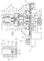
- the arm 34 of carriage 29 further carries at least one cutting unit 45 to be selectively switched on at the end of the above described winding step, to cut off the continuous elongated element 9 on a length thereof included between the pulley or other entry transmission 35 and the application devices 41. More specifically, the cutting unit 45 operates on the continuous elongated element 9 close to the end block 38, preferably at a point immediately upstream of said block.
- the cutting unit 45 comprises a guide block 46 fastened to the arm 34 of carriage 29 and having a through channel 47 extending along the feed direction "L", so that it is longitudinally passed through by the continuous elongated element 9.
- a slide seat 48 opening into the through channel 47 in a direction substantially perpendicular thereto.
- a punch 49 carrying a first cutting edge or movable cutting edge 50 at one end thereof.
- the movable cutting edge 50a co-operates with a second cutting edge or fixed cutting edge 50b, carried by the guide block 46, at a region where the slide seat 48 of punch 49 opens into the through channel 47.
- the cutting edges 50a, 50b are movable relative to each other to cut off the continuous elongated element 9 starting from a rest position to a cutting position.
- the fixed 50b and/or movable 50a cutting edges advantageously define a passage clearance 51 enclosing the continuous elongated element 9 at least partly; preferably the passage clearance 51 extends substantially in the form of a closed line around the continuous elongated element 9. More particularly, the passage clearance 51 is preferably defined by an opening of circular shape or other suitable outline formed in the fixed cutting edge 50b, in a continuity relationship with the through channel 47. Alternatively, the passage clearance 51 can be defined by two distinct portions, formed in the first and second cutting edges 50a, 50b, respectively.
- the first cutting edge 50a is movable upon command of a linear actuator 52, to which a thrust block 53 is rigidly connected, said thrust block 53 carrying an inclined plane 53a co-operating with a roller or other abutment element 54 carried by the punch 49 or connected to the first cutting edge 50a in a different manner.
- the action of the inclined plane enables amplification of the thrust transmitted to the first cutting edge 50a upon the action of the linear actuator 52.
- the thrust block 53 preferably has a return extension 55 having an auxiliary inclined plane 55a set to operate on the abutment roller 54 on the opposite side from said inclined plane 53a, to allow the first cutting edge 50a to return to a rest position, upon command of the linear actuator 52.
- arrangement of the passage clearance 51 enclosing the continuous elongated element 9 at least partly, in particular in a closed line around the element itself eliminates any possibility of side shifting of the elongated element between the cutting edges 50a, 50b, during mutual movement of the latter for carrying out a cutting action.
- a perfect cutting operation is ensured even when the continuous elongated element 9 is reinforced with steel cords or in any case cords made of a high-toughness material.
- the continuous elongated element 9 is submitted to an advancing step along the guide devices 35, 37 to set the free end of said elongated element 9 downstream of the cutting unit 45, to the grip position suitable for engagement of the elongated element itself by the application devices 41.
- feeding devices 56 comprising a slider 57 slidably guided relative to the arm 34 and movable in parallel to the longitudinal feed direction "L" of the continuous elongated element 9 in the length included between the entry transmission 35 and end guide 37.
- the slider 57 preferably carrying the cutting unit 45 and the previously described application devices 41, is movable with a reciprocating motion upon command of a linear feed actuator 64 fastened to the arm 34 and further carries at least one threading element 58 operating on the continuous elongated element 9 upstream of the cutting unit 45, to urge the elongated element in a step by step movement towards the forming drum 22, i.e. away from the entry pulley 35, together with the cutting unit itself.
- the threading element 58 is hinged with respect to slider 57 and has one free end 58a acting against the continuous elongated element 9 at a contact point located on the opposite side from a first abutment plate 59 carried by the slider itself.
- the contact point and the oscillation axis of the threading element 58 are aligned in a direction that with the longitudinal feed direction "L" of the continuous elongated element 9, forms an acute angle " ⁇ '" facing the cutting unit 45.
- the vertex formed of the acute angle " ⁇ "' is directed towards the cutting unit 45, as shown in Fig. 4 .
- Adjusting members can be associated with the linear feed actuator 64 to adapt the length of the stroke to the displacement amount to be imparted to the continuous elongated element 9 to set it to the grip position.
- the grip position can be reached by a single operation of the linear feed actuator 64 ( Fig. 6 ) or by a step by step moving forward following repeated driving actions of the actuator itself.
- the return-preventing devices 60 comprise at least one auxiliary grip element 61 oscillatably supported by the arm 34 and having one free end 61a acting against the continuous elongated element 9 on the opposite side from a second abutment plate 62 fixed with respect to the arm 34 itself.
- the contact point of the end of the auxiliary grip element 61, located upstream of the threading element 58 is in alignment with the oscillation axis of the grip element itself in a direction that with the longitudinal feed direction "L" of the continuous elongated element 9, forms an acute angle " ⁇ " facing the cutting unit 45.
- the auxiliary grip element 61 supported on a fixed oscillation axis with respect to the arm 34, is adapted to be wedged against the surface of the continuous elongated element 9 so as to prevent moving backwards of same during the return stroke of slider 37 to the entry pulley 35.
- the auxiliary grip element 61 allows easy sliding of the continuous elongated element.
- the guide duct 63 comprises a movable section 63a fixed with respect to slider 57 and a fixed section 63b, integral with respect to arm 34 and preferably fastened to the second abutment plate 62.
- the movable section 63a and fixed section 63b are telescopically slidable with respect to each other and longitudinally passed through by the continuous elongated element 9.
- the guide duct 63 therefore exerts an efficient annular containment action on the continuous elongated element 9 so that undesirable side deflections of the latter during the action of the feeding means are prevented.
Landscapes
- Engineering & Computer Science (AREA)
- Mechanical Engineering (AREA)
- Life Sciences & Earth Sciences (AREA)
- Forests & Forestry (AREA)
- Textile Engineering (AREA)
- Tyre Moulding (AREA)
Abstract
Claims (36)
- Appareil pour fabriquer des structures de renfort pour pneumatiques, comprenant :- un tambour de formage (22) pouvant être entraîné en rotation ;- des dispositifs pour guider vers le tambour de formage (22) un élément allongé continu (9) comprenant au moins une corde de renfort ;- des dispositifs (41) pour appliquer l'élément allongé continu (9) contre une surface de pose (22a) portée extérieurement par le tambour de formage (22) ;- au moins une unité (45) pour couper l'élément allongé continu (9) sur une longueur de celui-ci comprise entre les dispositifs de guidage (35, 37) et les dispositifs d'application (41) ;- des dispositifs d'alimentation (56) opérant sur l'élément allongé continu (9) pour disposer une extrémité libre de l'élément allongé continu (9) en une position de prise en aval de l'unité de coupe (45) ;dans lequel les dispositifs d'alimentation (56) comprennent un coulisseau (57) mobile dans un mouvement alternatif dans une direction d'alimentation longitudinale (« L ») de l'élément allongé continu (9), et au moins un élément d'enfilage (58) porté par le coulisseau (57) et opérant sur l'élément allongé continu (9) pour le bloquer par rapport au coulisseau (57) quand ce dernier se déplace vers le tambour de formage (22),
caractérisé en ce qu'il comprend en outre des dispositifs anti-retour (60) opérant sur l'élément allongé continu (9) en amont de l'unité de coupe (45), pour empêcher l'élément allongé continu (9) d'effectuer des mouvements de coulissement l'écartant de l'unité de coupe (45). - Appareil selon la revendication 1, dans lequel l'unité de coupe (45) est montée fonctionnellement sur ledit coulisseau (57).
- Appareil selon la revendication 1 ou 2, dans lequel l'unité de coupe (45) comprend une première arrête de coupe (50a) et une deuxième arrête de coupe (50b) qui sont mutuellement mobiles vers une position de coupe et avant d'atteindre la position de coupe, définissent un jeu de passage (51) entourant l'élément allongé continu (9) au moins partiellement.
- Appareil selon l'une ou plusieurs des revendications 1 à 3, dans lequel ledit élément d'enfilage (58) coulisse par rapport à l'élément allongé continu (9) lorsque le coulisseau (57) effectue un mouvement l'écartant du tambour de formage (22).
- Appareil selon l'une ou plusieurs des revendications 1 à 4, comprenant en outre au moins un conduit de guidage (63) traversé longitudinalement par l'élément allongé continu (9) pour empêcher des déviations latérales de l'élément allongé continu sur une longueur de celui-ci en amont de l'unité de coupe (45).
- Appareil selon l'une ou plusieurs des revendications 1 à 5, dans lequel lesdits dispositifs de guidage (35, 37), dispositifs d'application (41) et unité de coupe (45) sont portés par un chariot (29) qui est mobile parallèlement à un axe géométrique du tambour de formage (22), pour distribuer l'élément allongé continu en spires disposées mutuellement en relation côte à côte sur la surface de pose (22a) du tambour de formage (22) entraîné en rotation.
- Appareil selon la revendication 6, comprenant au moins deux desdits chariots portant respectivement des dispositifs de guidage (35, 37), des dispositifs d'application (41) et une unité de coupe (45), lesdits charriots (29) étant mobiles symétriquement par rapport à un plan équatorial du tambour de formage (22) pour former simultanément deux parties de ladite structure de renfort (9) disposées symétrique au plan équatorial.
- Installation pour fabriquer des pneumatiques, comprenant :- des dispositifs (12) pour faire une structure de carcasse (3) ;- des dispositifs (13) pour faire une structure de ceinture (6) ;- des dispositifs (28) pour appliquer la structure de ceinture (6) sur la structure de carcasse (3) en une position externe radialement de celle-ci ;dans laquelle les dispositifs (13) pour faire la structure de carcasse (6) comprennent au moins un appareil (25) pour former une structure de renfort (8) selon l'une ou plusieurs des revendications 1 à 7.
- Installation selon la revendication 3, dans laquelle le jeu de passage (51) est défini par une ouverture formée dans la deuxième arrête de coupe.
- Installation selon la revendication 8 lorsque dépendante de la revendication 3 ou 4, dans laquelle la première arrête de coupe (50a) est mobile sur commande d'un actionneur linéaire (52) opérant sur la première arrête de coupe au moyen d'un plan incliné (53a).
- Installation selon la revendication 10, dans laquelle le plan incliné (53a) est porté par un bloc de poussée (53) relié à l'actionneur linéaire (52) et coopérant avec une butée (54) reliée à la première arrête de coupe (50a) de l'unité de coupe (45).
- Installation selon la revendication 11, dans laquelle le bloc de poussée (53) a une extension de retour (55) portant un plan incliné auxiliaire (55a) opérant sur la butée sur le côté opposé dudit plan incliné (53a), pour ramener la première arrête de coupe (50B) en position de repos.
- Installation selon l'une quelconque ou plusieurs des revendications 8 à 12 dans laquelle les dispositifs d'alimentation (56) opèrent sur l'élément allongé continu (9) en amont de l'unité de coupe (45), pour provoquer une translation de l'élément allongé continu (9) vers la position de prise.
- Installation selon l'une quelconque ou plusieurs des revendications 8 à 13, dans laquelle ledit élément d'enfilage (58) coulisse par rapport à l'élément allongé continu (9) lorsque le coulisseau (57) effectue un mouvement en s'écartant du tambour de formage (22).
- Installation selon l'une quelconque ou plusieurs des revendications 8 à 15, dans laquelle ledit élément d'enfilage (58) a une extrémité libre (58a) agissant contre l'élément allongé continu (9) en un point de contact aligné avec un axe d'oscillation de l'élément d'enfilage dans une direction qui forme avec la direction d'alimentation longitudinale (« L ») de l'élément allongé continu un angle aigu (α') orienté vers l'unité de coupe (45).
- Installation selon la revendication 8, dans laquelle lesdits dispositifs anti-retour (60) comprennent au moins un élément de prise auxiliaire (61) ayant une extrémité libre (61a) agissant contre l'élément allongé continu en un point de contact aligné avec un axe d'oscillation de l'élément de prise auxiliaire, dans une direction qui forme avec la direction d'alimentation longitudinale (« L ») de l'élément allongé continu (9) un angle aigu (α") orienté vers l'unité de coupe (45).
- Installation selon la revendication 8 lorsque dépendante de la revendication 5, dans laquelle le conduit de guidage (63) comprend une partie mobile (63a) fixée par rapport au coulisseau (57) et une partie fixe (63b) solidaire de l'unité de coupe (45) et en prise télescopique avec la partie mobile (63a).
- Installation selon l'une quelconque ou plusieurs des revendications 8 à 17, dans laquelle les dispositifs d'application (41) comprennent au moins un rouleau presseur (42) fonctionnellement porté par un bras (34) oscillant entre une position de repos en laquelle le rouleau presseur (42) est éloigné du tambour de formage (22) et une position de travail en laquelle le rouleau presseur (42) fonctionne en relation de poussée sur l'élément allongé continu (9) pour le pousser contre la surface de pose (22a) du tambour de formage (22).
- Procédé pour fabrique une structure de renfort pour pneumatiques, comprenant les étapes d'enroulement d'au moins un élément allongé continu (9) comprenant au moins une corde de renfort sur un tambour de formage (22) pour former des spires circonférentielles disposées consécutivement en relation côte à côte, dans lequel l'enroulement est réalisé par les étapes de :- guider l'élément allongé continu (9) vers le tambour de formage (22) pouvant être entraîné en rotation ;- appliquer l'élément allongé continu (9) contre une surface de pose (22a) portée extérieurement par le tambour de formage (22) ;- couper l'élément allongé continu (9) par action d'une unité de coupe (45) ;- mettre une extrémité libre de l'élément allongé continu (9) en une position de prise en aval de l'unité de coupe (45) ;dans lequel l'étape consistant à mettre une extrémité libre de l'élément allongé continu (9) en une position de prise comprend les étapes de déplacement d'un coulisseau (57) mobile selon un mouvement alternatif dans une direction d'alimentation longitudinale (« L ») de l'élément allongé continu (9), de sorte que l'élément allongé continu (9) est amené en translation sur la position de prise par un mouvement pas à pas, et de blocage de l'élément allongé continu (9) par rapport au coulisseau (57) quand ce dernier se déplace vers le tambour de formage (22).
- Procédé selon la revendication 19, dans lequel l'unité de coupe (45) est montée fonctionnellement sur ledit coulisseau (57) et effectue une translation ensemble avec ce dernier.
- Procédé selon la revendication 19 ou 20, dans lequel l'unité de coupe, une première arrête de coupe (50a) et une deuxième arrête de coupe (50b) effectuent un mouvement mutuel vers une position de coupe, lesdites première et deuxième arrêtes de coupe définissant avant d'atteindre la position de coupe un jeu de passage (51) entourant l'élément allongé continu (9) au moins partiellement.
- Procédé selon l'une ou plusieurs des revendications 19 à 21, dans lequel l'étape consistant à placer une extrémité libre de l'élément allongé continu (9) en une position de prise comprend en outre l'étape consistant à effectuer une translation longitudinale du coulisseau (57) par rapport à l'élément allongé continu (9) lorsque le coulisseau s'éloigne du tambour de formage.
- Procédé selon l'une ou plusieurs des revendications 19 à 22, comprenant en outre une étape consistant à empêcher des mouvements de coulissement de l'élément allongé continu (9) par rapport à l'unité de coupe (45).
- Procédé selon l'une ou plusieurs des revendications 19 à 23, comprenant en outre l'étape consistant à empêcher des déviations latérales de l'élément allongé continu (9) au moins sur une longueur de celui-ci en amont de l'unité de coupe (45).
- Procédé selon l'une ou plusieurs des revendications 19 à 24, comprenant en outre l'étape de faire coulisser simultanément lesdits dispositifs de guidage (35, 37), dispositifs d'application (41) et unité de coupe (45) parallèlement à un axe géométrique du tambour de formage (22), pour distribuer l'élément allongé continu (9) en spires disposées dans une relation côte-à-côte mutuelle sur la surface de pose (22a) du tambour de formage (22) entrainé en rotation.
- Procédé selon l'une ou plusieurs des revendications 19 à 25, dans lequel au moins deux éléments allongés continus (9) sont simultanément posés sur le tambour de formage (22), pour former deux parties de ladite structure de renfort (8) disposées symétriquement par rapport au plan équatorial.
- Procédé pour fabriquer des pneumatiques, comprenant les étapes de:- fabriquer une structure de carcasse (3) ;- fabriquer une structure de ceinture (6) ;- appliquer la structure de ceinture (6) sur la structure de carcasse (3) en une position externe radialement de celle-ci ;dans lequel l'étape consistant à fabriquer la structure de ceinture (6) comprend une formation d'au moins une structure de renfort (8) selon l'une ou plusieurs des revendications 19 à 26.
- Procédé selon la revendication 27, lorsque dépendante de la revendication 21, dans lequel le jeu de passage (51) est défini par une ouverture disposée dans la seconde arrête de coupe (50b).
- Procédé selon l'une ou plusieurs des revendications 27 à 28, dans lequel l'étape de coupe est réalisée par translation de la première arrête de coupe (50a) sur commande d'un actionneur linéaire (52) opérant sur la première arrête de coupe au moyen d'un plan incliné (53a).
- Procédé selon la revendication 29, dans lequel le plan incliné (53a) est agencé sur un bloc de poussée (53) relié à l'actionneur linéaire (52) et coopérant avec une butée (54) reliée à la première arrête de coupe (50a) de l'unité de coupe (45).
- Procédé selon la revendication 30, dans lequel l'opération de coupe comprend en outre l'étape de ramener la première arrête de coupe (50a) à la position de repos au moyen d'un plan incliné auxiliaire (55a) disposé dans une extension de retour (55) portée par le bloc de poussée (53) et opérant sur la butée (54), sur le côté opposé audit plan incliné (53a).
- Procédé selon l'une ou plusieurs des revendications 27 à 31, dans lequel le blocage de l'élément allongé continu (9) par rapport au coulisseau (57) est réalisé par un élément d'enfilage (58) ayant une extrémité libre (58a) agissant contre l'élément allongé continu (9) en un point de contact aligné avec un axe d'oscillation de l'élément d'enfilage (58) dans une direction qui forme avec la direction d'alimentation longitudinale (« L ») de l'élément allongé continu un angle aigu (α') orienté vers l'unité de coupe (45).
- Procédé selon l'une ou plusieurs des revendications 27 à 32, dans lequel le coulissement de l'élément allongé continu (9) par rapport à l'unité de coupe (45) est empêché par une élément de prise auxiliaire (61) ayant une extrémité libre (61a) agissant contre l'élément allongé continu (9) en un point de contact aligné avec un axe d'oscillation de l'élément de prise auxiliaire (61), dans une direction qui forme avec la direction d'alimentation longitudinale (« L ») de l'élément allongé continu (9) un angle aigu (α") orienté vers l'unité de coupe (45).
- Procédé selon l'une ou plusieurs des revendications 27 à 33, dans lequel les déviations latérales de l'élément allongé continu (9) au moins sur une longueur de celui-ci en amont de l'unité de coupe (45), sont empêchées par guidage de l'élément allongé continu (9) le long d'au moins un conduit de guidage (63) traversé longitudinalement par l'élément allongé continu (9) lui-même.
- Procédé selon la revendication 34, dans lequel le conduit de guidage (63) comprend une partie mobile (63a) qui est fixée par rapport au coulisseau (57) et une partie fixe en prise télescopique avec la partie mobile (63a), des mouvements de coulissement mutuels entre la partie fixée (63b) et la partie mobile (63a) étant réalisés concurremment avec le mouvement pas-à-pas de l'élément allongé continu (9).
- Procédé selon l'une ou plusieurs des revendications 27 à 35, dans lequel une application de l'élément allongé continu (9) est réalisée par pressage de l'élément allongé continu contre la surface de pose (22a) sur le tambour de formage (22) au moyen d'un rouleau presseur (42).
Applications Claiming Priority (1)
| Application Number | Priority Date | Filing Date | Title |
|---|---|---|---|
| PCT/IT2005/000659 WO2007054984A1 (fr) | 2005-11-11 | 2005-11-11 | Installation de fabrication de pneumatiques et procede de fabrication associe |
Publications (2)
| Publication Number | Publication Date |
|---|---|
| EP1945443A1 EP1945443A1 (fr) | 2008-07-23 |
| EP1945443B1 true EP1945443B1 (fr) | 2012-05-16 |
Family
ID=36658838
Family Applications (1)
| Application Number | Title | Priority Date | Filing Date |
|---|---|---|---|
| EP05823483A Expired - Lifetime EP1945443B1 (fr) | 2005-11-11 | 2005-11-11 | Installation de fabrication de pneumatiques et procede de fabrication associe |
Country Status (5)
| Country | Link |
|---|---|
| US (2) | US20090250156A1 (fr) |
| EP (1) | EP1945443B1 (fr) |
| CN (1) | CN101304871B (fr) |
| BR (1) | BRPI0520688B1 (fr) |
| WO (1) | WO2007054984A1 (fr) |
Families Citing this family (15)
| Publication number | Priority date | Publication date | Assignee | Title |
|---|---|---|---|---|
| US20090250156A1 (en) | 2005-11-11 | 2009-10-08 | Mauro Bigogno | Plant for Manufacturing Tyres and Manufacturing Method Related Thereto |
| US7740039B2 (en) | 2005-12-01 | 2010-06-22 | The Goodyear Tire & Rubber Company | Cord cutting mechanism and method for a tire cord applicator head |
| EP2200814B1 (fr) | 2007-09-10 | 2014-01-08 | Pirelli Tyre S.P.A. | Traitement et appareil pour fabriquer une structure de renfort de pneumatiques de véhicules |
| CN102245374B (zh) * | 2008-12-11 | 2014-07-16 | 倍耐力轮胎股份公司 | 用于制造车轮轮胎的方法和设备 |
| EP2496407B1 (fr) | 2009-11-02 | 2015-12-23 | Pirelli Tyre S.p.A. | Procédé et appareil de fabrication de pneumatiques destinés à des roues de véhicules |
| US8585845B2 (en) * | 2010-11-10 | 2013-11-19 | The Goodyear Tire & Rubber Company | Tire-forming apparatus and related methods |
| WO2012146988A1 (fr) * | 2011-04-28 | 2012-11-01 | Pirelli Tyre S.P.A. | Procédé et équipement de construction de pneus pour des roues de véhicules |
| WO2013042255A1 (fr) * | 2011-09-22 | 2013-03-28 | 横浜ゴム株式会社 | Pneu |
| JP6063691B2 (ja) * | 2012-10-02 | 2017-01-18 | 住友ゴム工業株式会社 | ゴムストリップ巻回体形成装置 |
| DE102013103628A1 (de) * | 2013-04-11 | 2014-10-16 | Continental Reifen Deutschland Gmbh | Verfahren und Anlage zur Herstellung einer Karkasse für einen Fahrzeugluftreifen |
| DE102013103633A1 (de) | 2013-04-11 | 2014-10-16 | Continental Reifen Deutschland Gmbh | Verfahren und Anlage zur Herstellung einer Karkasse für einen Fahrzeugluftreifen |
| EP3233458B3 (fr) | 2014-12-19 | 2022-04-27 | Pirelli Tyre S.p.A. | Procédé et appareil permettant de fabriquer des pneus destinés aux roues de véhicule |
| US11135736B2 (en) | 2015-02-06 | 2021-10-05 | The Steelastic Company, Llc | Belt forming system |
| JP6920193B2 (ja) * | 2017-12-28 | 2021-08-18 | Toyo Tire株式会社 | タイヤ用ベルトの製造方法及び製造装置 |
| CN111055522B (zh) * | 2019-12-23 | 2022-06-10 | 杭州朝阳橡胶有限公司 | 一种零度缠绕供料装置 |
Family Cites Families (31)
| Publication number | Priority date | Publication date | Assignee | Title |
|---|---|---|---|---|
| US311785A (en) * | 1885-02-03 | Feeding device for screw | ||
| US3126138A (en) * | 1964-03-24 | onulak | ||
| DE326294C (de) * | 1917-10-02 | 1920-09-28 | Alfred De Fries | Vorrichtung zum Abstuetzen der Werkstuecke beim Abscheren an Schrauben- u. dgl. Pressen |
| US3148817A (en) * | 1962-08-20 | 1964-09-15 | Lawrence H Lord | Stock feeding mechanism for punch presses and the like |
| ZA721895B (en) * | 1971-03-23 | 1973-03-28 | Ellison Tufting Machinery Ltd | Cutting devices |
| DE2603861C3 (de) * | 1974-01-25 | 1978-11-30 | Skaltek Ab, Jaerfaella (Schweden) | Anordnung bei einer Wickelvorrichtung für fadenförmiges Gut |
| US3944457A (en) * | 1974-08-29 | 1976-03-16 | Minnesota Mining And Manufacturing Company | Strip material applying device |
| GB1487426A (en) | 1974-09-17 | 1977-09-28 | Bekaert Sa Nv | Reinforcement of vehicle tyres |
| US3904471A (en) * | 1974-10-15 | 1975-09-09 | Goodyear Tire & Rubber | Tire building apparatus |
| US4048884A (en) * | 1975-12-15 | 1977-09-20 | The Archilithic Company | Fiber shear system |
| US4063481A (en) * | 1976-10-12 | 1977-12-20 | Union Carbide Corporation | Rotary cutting device |
| US4218004A (en) * | 1978-12-21 | 1980-08-19 | American Can Company | Incremental strip feeder |
| JPS57105336A (en) * | 1980-12-23 | 1982-06-30 | Yokohama Rubber Co Ltd:The | Method and apparatus for feeding and winding material in green tire forming process |
| US4617074A (en) * | 1983-08-04 | 1986-10-14 | The Goodyear Tire & Rubber Company | Apparatus and method for feeding strip material for application to a drum |
| US4526647A (en) * | 1983-08-04 | 1985-07-02 | The Goodyear Tire & Rubber Company | Apparatus for feeding strip material for application to a drum |
| JPS61286124A (ja) * | 1985-06-14 | 1986-12-16 | Yokohama Rubber Co Ltd:The | タイヤ構成材料の供給装置 |
| JP2544117B2 (ja) * | 1986-10-23 | 1996-10-16 | 株式会社ブリヂストン | 細幅帯状体の供給装置 |
| IT1204980B (it) | 1987-04-28 | 1989-03-10 | Pirelli | Miglioramenti alle armature di rinforzo dei pneumatici per ruote di veicoli |
| JP2714959B2 (ja) * | 1988-09-29 | 1998-02-16 | 横浜ゴム株式会社 | 粘着性リボン状材料の自動巻付け方法及び装置 |
| US5335415A (en) * | 1991-10-30 | 1994-08-09 | Bridgestone Corporation | Apparatus for winding and pressure-fitting a small width strip to a rotating body |
| JP3202312B2 (ja) * | 1992-03-16 | 2001-08-27 | 株式会社ブリヂストン | シート状部材の貼付け装置 |
| JP3187954B2 (ja) * | 1992-07-21 | 2001-07-16 | 三菱重工業株式会社 | タイヤ成形システム |
| JP3745436B2 (ja) * | 1996-02-15 | 2006-02-15 | 株式会社ブリヂストン | タイヤ構成部材の送り出し切断装置 |
| FR2756213A1 (fr) * | 1996-11-27 | 1998-05-29 | Sedepro | Guide-fil a frein reglable, recevant des fils projetes sur une surface |
| SK283557B6 (sk) * | 1998-05-06 | 2003-09-11 | Matador, A. S. | Spôsob pokladania prekrývacieho nárazníka a zariadenie na vykonanie tohto spôsobu |
| EP1147865A3 (fr) * | 2000-04-18 | 2003-05-07 | Sedepro | Dispositif de coupe d'un fil |
| JP4167817B2 (ja) * | 2000-08-21 | 2008-10-22 | 不二精工株式会社 | タイヤの生産システム及び生産方法 |
| US6467149B2 (en) * | 2000-12-07 | 2002-10-22 | The Goodyear Tire & Rubber Company | Apparatus for injecting materials into a composite |
| AU2003233240A1 (en) * | 2002-05-29 | 2003-12-12 | Michelin Recherche Et Technique S.A. | Device and method for applying a strip to a rotary surface |
| JP4434771B2 (ja) * | 2004-02-12 | 2010-03-17 | 株式会社ブリヂストン | 帯状部材貼付装置 |
| US20090250156A1 (en) | 2005-11-11 | 2009-10-08 | Mauro Bigogno | Plant for Manufacturing Tyres and Manufacturing Method Related Thereto |
-
2005
- 2005-11-11 US US12/084,293 patent/US20090250156A1/en not_active Abandoned
- 2005-11-11 BR BRPI0520688A patent/BRPI0520688B1/pt active IP Right Grant
- 2005-11-11 CN CN2005800520378A patent/CN101304871B/zh not_active Expired - Lifetime
- 2005-11-11 WO PCT/IT2005/000659 patent/WO2007054984A1/fr not_active Ceased
- 2005-11-11 EP EP05823483A patent/EP1945443B1/fr not_active Expired - Lifetime
-
2017
- 2017-05-23 US US15/603,134 patent/US10730198B2/en active Active
Also Published As
| Publication number | Publication date |
|---|---|
| BRPI0520688B1 (pt) | 2016-07-26 |
| CN101304871A (zh) | 2008-11-12 |
| BRPI0520688A2 (pt) | 2009-09-29 |
| WO2007054984A1 (fr) | 2007-05-18 |
| US10730198B2 (en) | 2020-08-04 |
| US20090250156A1 (en) | 2009-10-08 |
| EP1945443A1 (fr) | 2008-07-23 |
| CN101304871B (zh) | 2012-06-27 |
| US20170320223A1 (en) | 2017-11-09 |
Similar Documents
| Publication | Publication Date | Title |
|---|---|---|
| US10730198B2 (en) | Plant for manufacturing tyres and manufacturing method related thereto | |
| US6979378B2 (en) | Tire forming system and tire forming method | |
| CN105189099B (zh) | 用于制造用于车辆车轮的轮胎的工艺和设备 | |
| EP3225386B1 (fr) | Systeme de reglage de la trajectoire d'un fil | |
| CN100386194C (zh) | 包括条带翻转机构的用于制造轮胎加强结构的装置 | |
| JP5265251B2 (ja) | コード切断装置 | |
| EP2871049B1 (fr) | Appareil de découpe et d'enroulement d'un matériau de carcasse pour pneus | |
| CN107000350B (zh) | 用于构建车辆车轮的轮胎的工艺和设备 | |
| US10926501B2 (en) | Method, process and apparatus for building tyres for vehicle wheels | |
| EP1279485B1 (fr) | Procédé de fabrication de peumatique contenant une couche renforcée par des cordes | |
| KR101111139B1 (ko) | 차륜용 타이어 제조를 위한 반제품 생산방법 및 장치 | |
| CN100548651C (zh) | 生胎带束层加强用带料的供给装置 | |
| EP3089931B1 (fr) | Procédé de guidage d'un élément allongé pour un procédé de fabrication de pneus de roue de véhicule et appareil de fabrication de pneus de roue de véhicule | |
| JP5215047B2 (ja) | シングルラインプライの製造方法 | |
| CN104023963B (zh) | 用于制造相互不同的轮胎的工艺和设备 | |
| EP2006078B1 (fr) | Appareil de découpe de corde pour pneu et procédé de construction de pli de pneu à ligne unique |
Legal Events
| Date | Code | Title | Description |
|---|---|---|---|
| PUAI | Public reference made under article 153(3) epc to a published international application that has entered the european phase |
Free format text: ORIGINAL CODE: 0009012 |
|
| 17P | Request for examination filed |
Effective date: 20080414 |
|
| AK | Designated contracting states |
Kind code of ref document: A1 Designated state(s): AT BE BG CH CY CZ DE DK EE ES FI FR GB GR HU IE IS IT LI LT LU LV MC NL PL PT RO SE SI SK TR |
|
| 17Q | First examination report despatched |
Effective date: 20081216 |
|
| GRAP | Despatch of communication of intention to grant a patent |
Free format text: ORIGINAL CODE: EPIDOSNIGR1 |
|
| DAX | Request for extension of the european patent (deleted) | ||
| GRAS | Grant fee paid |
Free format text: ORIGINAL CODE: EPIDOSNIGR3 |
|
| GRAA | (expected) grant |
Free format text: ORIGINAL CODE: 0009210 |
|
| AK | Designated contracting states |
Kind code of ref document: B1 Designated state(s): AT BE BG CH CY CZ DE DK EE ES FI FR GB GR HU IE IS IT LI LT LU LV MC NL PL PT RO SE SI SK TR |
|
| REG | Reference to a national code |
Ref country code: GB Ref legal event code: FG4D |
|
| REG | Reference to a national code |
Ref country code: CH Ref legal event code: EP |
|
| REG | Reference to a national code |
Ref country code: AT Ref legal event code: REF Ref document number: 557863 Country of ref document: AT Kind code of ref document: T Effective date: 20120615 |
|
| REG | Reference to a national code |
Ref country code: IE Ref legal event code: FG4D |
|
| REG | Reference to a national code |
Ref country code: DE Ref legal event code: R096 Ref document number: 602005034242 Country of ref document: DE Effective date: 20120712 |
|
| REG | Reference to a national code |
Ref country code: RO Ref legal event code: EPE |
|
| REG | Reference to a national code |
Ref country code: NL Ref legal event code: T3 |
|
| REG | Reference to a national code |
Ref country code: LT Ref legal event code: MG4D Effective date: 20120516 |
|
| PG25 | Lapsed in a contracting state [announced via postgrant information from national office to epo] |
Ref country code: CY Free format text: LAPSE BECAUSE OF FAILURE TO SUBMIT A TRANSLATION OF THE DESCRIPTION OR TO PAY THE FEE WITHIN THE PRESCRIBED TIME-LIMIT Effective date: 20120516 Ref country code: FI Free format text: LAPSE BECAUSE OF FAILURE TO SUBMIT A TRANSLATION OF THE DESCRIPTION OR TO PAY THE FEE WITHIN THE PRESCRIBED TIME-LIMIT Effective date: 20120516 Ref country code: LT Free format text: LAPSE BECAUSE OF FAILURE TO SUBMIT A TRANSLATION OF THE DESCRIPTION OR TO PAY THE FEE WITHIN THE PRESCRIBED TIME-LIMIT Effective date: 20120516 Ref country code: IS Free format text: LAPSE BECAUSE OF FAILURE TO SUBMIT A TRANSLATION OF THE DESCRIPTION OR TO PAY THE FEE WITHIN THE PRESCRIBED TIME-LIMIT Effective date: 20120916 Ref country code: SE Free format text: LAPSE BECAUSE OF FAILURE TO SUBMIT A TRANSLATION OF THE DESCRIPTION OR TO PAY THE FEE WITHIN THE PRESCRIBED TIME-LIMIT Effective date: 20120516 Ref country code: PL Free format text: LAPSE BECAUSE OF FAILURE TO SUBMIT A TRANSLATION OF THE DESCRIPTION OR TO PAY THE FEE WITHIN THE PRESCRIBED TIME-LIMIT Effective date: 20120516 |
|
| REG | Reference to a national code |
Ref country code: AT Ref legal event code: MK05 Ref document number: 557863 Country of ref document: AT Kind code of ref document: T Effective date: 20120516 |
|
| PG25 | Lapsed in a contracting state [announced via postgrant information from national office to epo] |
Ref country code: GR Free format text: LAPSE BECAUSE OF FAILURE TO SUBMIT A TRANSLATION OF THE DESCRIPTION OR TO PAY THE FEE WITHIN THE PRESCRIBED TIME-LIMIT Effective date: 20120817 Ref country code: LV Free format text: LAPSE BECAUSE OF FAILURE TO SUBMIT A TRANSLATION OF THE DESCRIPTION OR TO PAY THE FEE WITHIN THE PRESCRIBED TIME-LIMIT Effective date: 20120516 Ref country code: PT Free format text: LAPSE BECAUSE OF FAILURE TO SUBMIT A TRANSLATION OF THE DESCRIPTION OR TO PAY THE FEE WITHIN THE PRESCRIBED TIME-LIMIT Effective date: 20120917 Ref country code: SI Free format text: LAPSE BECAUSE OF FAILURE TO SUBMIT A TRANSLATION OF THE DESCRIPTION OR TO PAY THE FEE WITHIN THE PRESCRIBED TIME-LIMIT Effective date: 20120516 |
|
| PG25 | Lapsed in a contracting state [announced via postgrant information from national office to epo] |
Ref country code: BE Free format text: LAPSE BECAUSE OF FAILURE TO SUBMIT A TRANSLATION OF THE DESCRIPTION OR TO PAY THE FEE WITHIN THE PRESCRIBED TIME-LIMIT Effective date: 20120516 |
|
| PG25 | Lapsed in a contracting state [announced via postgrant information from national office to epo] |
Ref country code: DK Free format text: LAPSE BECAUSE OF FAILURE TO SUBMIT A TRANSLATION OF THE DESCRIPTION OR TO PAY THE FEE WITHIN THE PRESCRIBED TIME-LIMIT Effective date: 20120516 Ref country code: EE Free format text: LAPSE BECAUSE OF FAILURE TO SUBMIT A TRANSLATION OF THE DESCRIPTION OR TO PAY THE FEE WITHIN THE PRESCRIBED TIME-LIMIT Effective date: 20120516 Ref country code: AT Free format text: LAPSE BECAUSE OF FAILURE TO SUBMIT A TRANSLATION OF THE DESCRIPTION OR TO PAY THE FEE WITHIN THE PRESCRIBED TIME-LIMIT Effective date: 20120516 Ref country code: CZ Free format text: LAPSE BECAUSE OF FAILURE TO SUBMIT A TRANSLATION OF THE DESCRIPTION OR TO PAY THE FEE WITHIN THE PRESCRIBED TIME-LIMIT Effective date: 20120516 Ref country code: SK Free format text: LAPSE BECAUSE OF FAILURE TO SUBMIT A TRANSLATION OF THE DESCRIPTION OR TO PAY THE FEE WITHIN THE PRESCRIBED TIME-LIMIT Effective date: 20120516 |
|
| PLBE | No opposition filed within time limit |
Free format text: ORIGINAL CODE: 0009261 |
|
| STAA | Information on the status of an ep patent application or granted ep patent |
Free format text: STATUS: NO OPPOSITION FILED WITHIN TIME LIMIT |
|
| 26N | No opposition filed |
Effective date: 20130219 |
|
| PG25 | Lapsed in a contracting state [announced via postgrant information from national office to epo] |
Ref country code: ES Free format text: LAPSE BECAUSE OF FAILURE TO SUBMIT A TRANSLATION OF THE DESCRIPTION OR TO PAY THE FEE WITHIN THE PRESCRIBED TIME-LIMIT Effective date: 20120827 |
|
| REG | Reference to a national code |
Ref country code: DE Ref legal event code: R097 Ref document number: 602005034242 Country of ref document: DE Effective date: 20130219 |
|
| REG | Reference to a national code |
Ref country code: CH Ref legal event code: PL |
|
| PG25 | Lapsed in a contracting state [announced via postgrant information from national office to epo] |
Ref country code: BG Free format text: LAPSE BECAUSE OF FAILURE TO SUBMIT A TRANSLATION OF THE DESCRIPTION OR TO PAY THE FEE WITHIN THE PRESCRIBED TIME-LIMIT Effective date: 20120816 Ref country code: LI Free format text: LAPSE BECAUSE OF NON-PAYMENT OF DUE FEES Effective date: 20121130 Ref country code: CH Free format text: LAPSE BECAUSE OF NON-PAYMENT OF DUE FEES Effective date: 20121130 |
|
| REG | Reference to a national code |
Ref country code: IE Ref legal event code: MM4A |
|
| PG25 | Lapsed in a contracting state [announced via postgrant information from national office to epo] |
Ref country code: IE Free format text: LAPSE BECAUSE OF NON-PAYMENT OF DUE FEES Effective date: 20121111 |
|
| PG25 | Lapsed in a contracting state [announced via postgrant information from national office to epo] |
Ref country code: MC Free format text: LAPSE BECAUSE OF NON-PAYMENT OF DUE FEES Effective date: 20121130 |
|
| PG25 | Lapsed in a contracting state [announced via postgrant information from national office to epo] |
Ref country code: LU Free format text: LAPSE BECAUSE OF NON-PAYMENT OF DUE FEES Effective date: 20121111 |
|
| PG25 | Lapsed in a contracting state [announced via postgrant information from national office to epo] |
Ref country code: HU Free format text: LAPSE BECAUSE OF FAILURE TO SUBMIT A TRANSLATION OF THE DESCRIPTION OR TO PAY THE FEE WITHIN THE PRESCRIBED TIME-LIMIT Effective date: 20051111 |
|
| REG | Reference to a national code |
Ref country code: FR Ref legal event code: PLFP Year of fee payment: 11 |
|
| REG | Reference to a national code |
Ref country code: FR Ref legal event code: PLFP Year of fee payment: 12 |
|
| REG | Reference to a national code |
Ref country code: FR Ref legal event code: GC Effective date: 20170203 |
|
| REG | Reference to a national code |
Ref country code: FR Ref legal event code: RG Effective date: 20170707 |
|
| REG | Reference to a national code |
Ref country code: FR Ref legal event code: PLFP Year of fee payment: 13 |
|
| PGFP | Annual fee paid to national office [announced via postgrant information from national office to epo] |
Ref country code: NL Payment date: 20241126 Year of fee payment: 20 |
|
| PGFP | Annual fee paid to national office [announced via postgrant information from national office to epo] |
Ref country code: DE Payment date: 20241127 Year of fee payment: 20 |
|
| PGFP | Annual fee paid to national office [announced via postgrant information from national office to epo] |
Ref country code: GB Payment date: 20241127 Year of fee payment: 20 |
|
| PGFP | Annual fee paid to national office [announced via postgrant information from national office to epo] |
Ref country code: FR Payment date: 20241128 Year of fee payment: 20 |
|
| PGFP | Annual fee paid to national office [announced via postgrant information from national office to epo] |
Ref country code: RO Payment date: 20241023 Year of fee payment: 20 |
|
| PGFP | Annual fee paid to national office [announced via postgrant information from national office to epo] |
Ref country code: IT Payment date: 20241122 Year of fee payment: 20 |
|
| PGFP | Annual fee paid to national office [announced via postgrant information from national office to epo] |
Ref country code: TR Payment date: 20241031 Year of fee payment: 20 |
|
| REG | Reference to a national code |
Ref country code: DE Ref legal event code: R071 Ref document number: 602005034242 Country of ref document: DE |
|
| REG | Reference to a national code |
Ref country code: NL Ref legal event code: MK Effective date: 20251110 |
|
| REG | Reference to a national code |
Ref country code: GB Ref legal event code: PE20 Expiry date: 20251110 |