EP1945976B1 - Soupape a double siege - Google Patents
Soupape a double siege Download PDFInfo
- Publication number
- EP1945976B1 EP1945976B1 EP06723949A EP06723949A EP1945976B1 EP 1945976 B1 EP1945976 B1 EP 1945976B1 EP 06723949 A EP06723949 A EP 06723949A EP 06723949 A EP06723949 A EP 06723949A EP 1945976 B1 EP1945976 B1 EP 1945976B1
- Authority
- EP
- European Patent Office
- Prior art keywords
- seat
- closing element
- seat valve
- valve according
- double seat
- Prior art date
- Legal status (The legal status is an assumption and is not a legal conclusion. Google has not performed a legal analysis and makes no representation as to the accuracy of the status listed.)
- Expired - Lifetime
Links
Images



Classifications
-
- F—MECHANICAL ENGINEERING; LIGHTING; HEATING; WEAPONS; BLASTING
- F16—ENGINEERING ELEMENTS AND UNITS; GENERAL MEASURES FOR PRODUCING AND MAINTAINING EFFECTIVE FUNCTIONING OF MACHINES OR INSTALLATIONS; THERMAL INSULATION IN GENERAL
- F16K—VALVES; TAPS; COCKS; ACTUATING-FLOATS; DEVICES FOR VENTING OR AERATING
- F16K1/00—Lift valves or globe valves, i.e. cut-off apparatus with closure members having at least a component of their opening and closing motion perpendicular to the closing faces
- F16K1/32—Details
- F16K1/34—Cutting-off parts, e.g. valve members, seats
- F16K1/44—Details of seats or valve members of double-seat valves
- F16K1/443—Details of seats or valve members of double-seat valves the seats being in series
- F16K1/446—Details of seats or valve members of double-seat valves the seats being in series with additional cleaning or venting means between the two seats
-
- Y—GENERAL TAGGING OF NEW TECHNOLOGICAL DEVELOPMENTS; GENERAL TAGGING OF CROSS-SECTIONAL TECHNOLOGIES SPANNING OVER SEVERAL SECTIONS OF THE IPC; TECHNICAL SUBJECTS COVERED BY FORMER USPC CROSS-REFERENCE ART COLLECTIONS [XRACs] AND DIGESTS
- Y10—TECHNICAL SUBJECTS COVERED BY FORMER USPC
- Y10T—TECHNICAL SUBJECTS COVERED BY FORMER US CLASSIFICATION
- Y10T137/00—Fluid handling
- Y10T137/4238—With cleaner, lubrication added to fluid or liquid sealing at valve interface
- Y10T137/4245—Cleaning or steam sterilizing
- Y10T137/4259—With separate material addition
-
- Y—GENERAL TAGGING OF NEW TECHNOLOGICAL DEVELOPMENTS; GENERAL TAGGING OF CROSS-SECTIONAL TECHNOLOGIES SPANNING OVER SEVERAL SECTIONS OF THE IPC; TECHNICAL SUBJECTS COVERED BY FORMER USPC CROSS-REFERENCE ART COLLECTIONS [XRACs] AND DIGESTS
- Y10—TECHNICAL SUBJECTS COVERED BY FORMER USPC
- Y10T—TECHNICAL SUBJECTS COVERED BY FORMER US CLASSIFICATION
- Y10T137/00—Fluid handling
- Y10T137/8593—Systems
- Y10T137/87917—Flow path with serial valves and/or closures
- Y10T137/88022—One valve head provides seat for other head
-
- Y—GENERAL TAGGING OF NEW TECHNOLOGICAL DEVELOPMENTS; GENERAL TAGGING OF CROSS-SECTIONAL TECHNOLOGIES SPANNING OVER SEVERAL SECTIONS OF THE IPC; TECHNICAL SUBJECTS COVERED BY FORMER USPC CROSS-REFERENCE ART COLLECTIONS [XRACs] AND DIGESTS
- Y10—TECHNICAL SUBJECTS COVERED BY FORMER USPC
- Y10T—TECHNICAL SUBJECTS COVERED BY FORMER US CLASSIFICATION
- Y10T137/00—Fluid handling
- Y10T137/8593—Systems
- Y10T137/87917—Flow path with serial valves and/or closures
- Y10T137/88038—One valve head carries other valve head
Definitions
- the invention relates to a double-seat valve having two serially arranged, relatively movable closure members which prevent in the closed position of the double seat valve, the overflow of fluids from one valve housing part to another, which define a leakage cavity between them in both the closed and in the open position, which is connected to the environment of the double seat valve, wherein in the closed position formed as a slide piston first closing member in a valve housing parts interconnecting connection opening sealingly receiving and in the course of its opening movement on a second seat associated second closing member sealingly comes to rest and the latter in the other Opening movement is also transferred to an open position, wherein the first closing member has at its end portion a first seal, which is radially opposite to a formed in the connection opening Zylinderis the first closing member facing a recess having a substantially cylindrical, aligned with the cylindrical first seat peripheral wall, and the recess is dimensioned to during the opening movement of the end portion and the radial first Sealing of the first closing member to receive sealing before the second closing member opens, and with
- the prototype of a double-seat valve which has essential features of a double-seat veritil of the generic type, is known from EP 0 039 319 B1 known.
- the first closing member has at its end portion a seal radially against a formed in the connecting opening cylindrical first seat seals (seal with sliding engagement), wherein the second closing member at its the first Closing member 3 facing the end has a recess with a substantially cylindrical, aligned with the cylindrical first seat peripheral wall, and the recess is dimensioned to receive during the opening movement, the end portion and the radial seal of the first closing member sealingly before the second closing member opens.
- the second closing member is designed as a seat plate, whose seal acts purely axially on the associated seat (seal with pressure engagement).
- the well-known double seat valve according to EP 0 039 319 B1 learns its further development by a double seat valve of the generic type, as it is known from WO 98 54 494 A1 is known.
- the further development consists in that the double seat valve now has two so-called seat cleaning positions, wherein the first seat cleaning position is generated by a first partial lift directed counter to the opening stroke. In this position, the leakage chamber on the first closing member arranged cylindrical projection forms with the associated cylindrical first seat a so-called. Throttle gap, via which the zoom out of the adjacent first valve body part detergent amount can be limited.
- the seat cleaning position of the second closing member is effected by a opening stroke rectified second partial stroke, wherein in the partially open position of the leakage chamber side arranged on the second closing member cylindrical projection with the associated part of the connecting opening forms a second throttle gap, which limits the amount generated in this seat cleaning second seat cleaning flow.
- the respectively assigned sections of the connecting opening are likewise different in diameter, so that a transitional surface is established between these two diameters.
- the first seat cleaning flow flows along the cylindrical first seat surface, overflows the annular gap formed between the transition surface and the cylindrical extension on the second closing member and settles along the peripheral wall of the cylindrical recess in the second closing member, which is aligned with the cylindrical seat , wherein the diameter difference between the two sections of the connecting opening prevents at least direct impact of the first seat cleaning flow on the second throttle gap and thus the seating area of the second closing element.
- the in the seat cleaning position of the first closing member on the cylindrical wall of the first seat and the adjoining cylindrical peripheral wall along seat cleaning flow bounces against the frontal boundary of the cylindrical recess, which is preferably oriented perpendicular to the aligned cylindrical surfaces.
- Such a rectangular deflection of the flow is generally unfavorable, it triggers uncontrolled from the wall and creates vortexes and circulation flows, which may be accumulation pressure forming.
- the shape and dimension of the cylindrical first seat in the valve housing determine the shape and dimension of the recess in the second closing member in the region of the peripheral wall.
- the second seat cleaning flow is deflected radially inwardly at the diameter difference between the sections of the connecting opening bridging transition surface and guided past the upper end boundary surface of the first closing member. Also in this case, an immediate impact of the second seat cleaning flow on the first throttle gap and thus the seating area of the first closing member is prevented.
- such a double seat valve is not only the demand for limiting the amount of detergent and avoid direct application of the seat areas in the course of seat cleaning, but also after a possible turbulence-free removal of the seat cleaning flow first in the leakage cavity and from there into the environment, without that the respective closed seating area is directly flowed by this seat cleaning flow or subjected to pressure-increasing.
- Direct loading is understood to mean any velocity component from the respective seat cleaning flow that is directed perpendicularly to the walls delimiting the seat area.
- any direct application in this regard leads to a conversion of kinetic flow energy into static pressure.
- a branch flow with a so-called. "Branch flow line”, the latter divides the flow in two halves.
- the branch streamline itself runs on the so-called “stagnation point”, so that at this point the speed is zero.
- Of the Pressure increase as a result of this stopping of the speed also receives the designation "back pressure”.
- the pressure-increasing mechanisms described above if effective, generate a leakage flow across the respective throttle gap and the defective or completely out-of-place seat seal.
- the relevant seat cleaning flow is directed by the conical transition surface on the end face of the first closing member in close proximity to the annular gap between the cylindrical projection on the first closing member and the cylindrical first seat.
- the present invention is based on the basic features of the known double seat valve according to WO 98 54 494 A1 with the respective closure member on the leakage chamber side arranged cylindrical approach to form the respective throttle gap.
- the present invention utilizes the difference in diameter of these cylindrical lugs, which allows the formation of a transition surface between the different diameter portions of the connection opening associated with the cylindrical lugs.
- a first inventive concept is to initiate the seat cleaning flow exiting from the associated throttle gap during the respective seat cleaning as far as possible without turbulence and obstacle in the leakage cavity and dissipate it from there in the same way in the environment.
- This is achieved on the one hand by a new, the seat cleaning flows in the leakage cavity leading and directing flow contour. With the seat cleaning of the lower, first closing element, this new flow contour ensures that the first seat cleaning flow follows the course of the wall in the area of the first seat without separation.
- the deflection surface has a contour with kink-free course, wherein a directional vector points in the Ausmündungsyak the deflection in a arranged in the first closing member centric drain hole, without the first closing member in the region of the leakage cavity gebandenden areas forming staullingend to collide. It is also essential that the peripheral wall of the cylindrical recess with the end face of the cylindrical projection on the second closing member forms a second peripheral edge, which directly adjoins the first seat in the closed position of the second closing member.
- a second inventive basic idea is, the end position limit of the second closing member (spool with radially acting seal in sliding or possibly seat plate with radial / axial acting seal in sliding / pressure engagement or conditionally seat plate with axially acting seal in the pressure engagement) in the closed position not at the cooperating with the seal seating area, as in the generic double-seat valve according to WO 98 54 494 A1
- the end portion of the second cylindrical projection is configured radially on the outside following the stop surface in such a way that an annular circumferential centering point is formed here.
- This centering point is, as seen in the radial direction, as far as possible shifted outwards and brought as close as possible to the determined by a radius of curvature course of the transition surface.
- an annular circumferential second bevel which is provided at the end portion and against the stop surface extends at a bevel angle and which forms, together with the second diameter of the second cylindrical projection, a rounding edge produced by rounding which ensures centering in the transition surface.
- the second seat cleaning flow generated by ventilating the second closing element it is essential that it be detached in a defined manner at a first peripheral edge formed by the transition surface and the first seating surface and tangentially guided past the surfaces surrounding the first closing element in the area of the leakage cavity.
- a safety distance is provided between the first peripheral edge and the areas of interest of the first closing member, which prevents a relevant impact under all possible technical conditions.
- the safety distance of the first closing member from the directional vector at the exit point of the transition surface in the first seat is advantageously dimensioned such that it is at least as large as the sum of all manufacturing tolerances of the components of the double seat valve, which in the closed position of the first closing member whose smallest axial distance from the transition surface determine.
- the annular recess in the housing forms with the transition surface an obtuse or a vertical first deflection angle, the vertical deflection angle (90 degrees) being preferred.
- the transition between the recess and the transition surface is advantageously rounded with a fillet radius.
- the deflection surface undercuts the end face by an axial Schuschungsabstand.
- the contour of the deflection surface in the region of its Ausmündungsconces be hired by a third deflection relative to the end face of the cylindrical recess, that the first seat cleaning flow is slightly deflected toward the second closing member and then the wall of the adjacent end face of the cylindrical recess for the purpose of Cleaning them can follow.
- the third deflection angle is carried out in the range of 5 to 20 degrees, preferably 15 degrees.
- a contour has proven to have a sequence of sections, the first section and the third and last section opening out from the end face are respectively rectilinear, and wherein these sections on the second section, the latter tangentially rounded with a maximum deflection radius, are interconnected.
- contour is composed of a sequence of curved sections which each have a common tangent at their respective transition points.
- Another embodiment provides that the contour consists of a single section of continuously changed curvatures.
- the contour is formed from a single section of constant curvature.
- the drain hole connects via a plurality of circumferentially distributed connection holes the leakage cavity with the environment of the double seat valve, and that the leakage cavity facing the frontal boundary of the first closing member a on all sides has circumferential, sloping slope to the drain hole.
- the drain hole connects the leakage cavity with the environment of the double seat valve, and that the leakage cavity facing the frontal boundary of the first closing member has a well circumferentially to the drain hole sloping bevel.
- a first adjusting rod connected to the first closing member penetrates a connected to the second closing member, designed as a hollow rod second adjusting rod concentric, continues to fly through the drain hole and is connected at one end remote from the second closing member of the first closing member with the latter via at least one substantially radially oriented traverse.
- the aforementioned chamfer of the leakage cavity facing end surface of the first closing member is suitably designed as a conical surface, which is inclined relative to the base of the cone in the range of 10 to 20 degrees, preferably 15 degrees.
- the welding part on the outside of the ring to a leakage leakage chamber distal portion of the drain hole delimiting pressure equalizing piston and on the inside adjoins the Verstellstangenabites to the first adjusting and if the ring in its inner diameter so compared to the diameter of the drain hole with the interposition of a conical widening transition region is increased, that the internal passage of the drain hole is not diminished by the trusses.
- the invention according to a first embodiment provides that the second seat is cylindrical and formed by the annular recess, that the second closing member has a second seal which seals radially relative to the second seat in sliding engagement.
- the second seat has a beveled edge which widens towards the second closing member to achieve a smooth transition of the radial second seal. This bevelled edge is compared to the second seat by an angle, preferably in the range 7.5 to 15 degrees, preferably employed with 10 degrees.
- a second embodiment relating to the second seat provides that the second seat is tapered and inclined relative to the cylindrical recess by a seat angle, and that the second shutter has a second seal axially / radially opposed to the second seat in sliding / pressure engagement seals.
- the seat angle is here in the range between 25 and 35 degrees, preferably performed at 30 degrees.
- the second seat expands at its end facing the second closing element into an opening bevel, the latter being set opposite the cylindrical recess by an opening angle already quantified above.
- the second seat surface is arranged perpendicular to the longitudinal axis of the double seat valve, and that the second closing member has a second seal which seals axially relative to the second seat surface in pressure engagement.
- the seal is made ductile such that the solid and possibly metallic contact of the second closing member with its stop surface alone at the transition surface below all conditions is ensured.
- the double seat valve 1 according to the invention FIG. 1 ) consists essentially of the valve housing 10 having a first and a second valve housing part 1a and 1b, the two independently movable closure members 3 and 4 with the respectively associated adjustment rods 3a and 4a and a seat ring 2, the via an inside connection opening 2c a Connection between the valve body parts 1a, 1b manufactures.
- the first closing element 3 (active closing element) designed as a slide piston is sealingly received in a first seating surface 2a formed by the connecting opening 2c, which is designed as a cylindrical seating surface.
- a first seal 6 is provided in the spool 3, which exclusively by radial bias with the first seat 2a cooperates (radial seal in sliding engagement).
- the formed as a seat plate second closing member 4 cooperates in the closed position of the double seat valve 1 with a conical second seat 2b, which opens to the first closing member 3 out in a substantially cylindrical annular recess 2d.
- the sealing takes place via a second seal 7 which seals axially / radially with respect to the second seat surface 2b in sliding / pressure engagement.
- the two closing members 3, 4 form both in the illustrated closed position and in an open position (FIG. FIG. 3 ) between them a leakage cavity 5, which is connected via a non-illustrated drain hole 3d, which is a centrally connected to the first closing member 3 connecting part 3b and a continuation of the latter pressure equalizing piston 3c, with the environment of the double seat valve 1 (see also FIG. 6b ).
- FIG. 1 shows, the first adjusting rod 3a in the region of the first closing member 3 with the latter via a plurality of the drain hole 3d star-shaped and radially passing through webs.
- these webs are formed between connecting holes 3d *, distributed over the circumference penetrate the closing member 3 and connect the drain hole 3d with the leakage cavity 5.
- these mechanically necessary joints in the form of three evenly distributed over the circumference arranged trusses 3e a distance away from the leakage cavity 5, preferably to the first closing member 3 facing away from the end of the pressure compensating piston 3c, to relocate ( FIG. 6b ).
- the firm connection with the latter takes place via a circumferential ring 3g, with which the trusses 3e are firmly connected radially on the outside.
- the trusses 3e, the ring 3g and an adjusting rod section 3a * are expediently combined in a one-piece welding part 30 ( FIG. 6a ).
- Each closing member 3, 4 has on the leakage chamber side a cylindrical projection 3 * or 4 * which, with the associated part of the connection opening 2c in the seat ring 2, has an annular first throttle gap D1 (see also FIG. 4 ) or an annular second throttle gap D2 (see also FIG. 5 ).
- the second closing element 4 has, at its end facing the first closing element 3, a recess 4b with a substantially cylindrical peripheral wall 4c (FIG. 2c) aligned with the cylindrical first seating surface 2a (FIG. FIG. 1 ).
- This peripheral wall 4c is dimensioned so that it sealingly receives the end portion 3 * and the radial first seal 6 of the first closing member 3 during the opening movement, before the second closing member 4 opens.
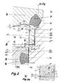
- FIGS. 2 to 5 clarify in connection with FIG. 1 Details of the seating area for the double-seated valve 1.
- the first closing element 3 forms with its cylindrical projection 3 * (FIG. FIG. 2 ; FIG. 4 ) having a first diameter d1, and with the associated first seating surface 2a of the communication opening 2c, the first throttle gap D1.
- the second closing member 4 forms in the same way with its second cylindrical projection 4 * ( FIG. 1 ; FIG. 5 ), which has a second diameter d2, together with the annular, cylindrical recess 2d in the connection opening 2c, the second throttle gap D2.
- the half diameter difference between the annular recess 2d and the first seat 2a (FIG. FIG. 5 ; FIG. 2 and 1 ) is marked with a.
- the transition surface 2e is provided between the first seat surface 2a and the annular recess 2d, the end section of the transition surface 2e opening into the first seat surface 2a forming a preferably vertical first deflection angle ⁇ with the cylindrical surface of the annular recess 2d.
- the annular recess 2d in the connection opening 2c has a rounded transition with the radius of curvature r1 to the transition surface 2e, the radius of curvature r1 being carried out with r1 ⁇ a.
- the radial width a is made so large that in the seat cleaning position of the second closing member 4th from the second throttle gap D2 in the leakage cavity 5 exiting second seat cleaning flow R2 ( FIG. 5 ) is deflected at the transition surface 2 e toward the center of the leakage cavity 5 and securely over the first closure member 3 away.
- a first peripheral edge U1 formed by the transitional surface 2e and the first seat 2a is rounded with a smallest possible first corner rounding r3, whereby a defined stall occurs at this point ,
- the radial width a of the transition surface 2e must also be the realization of a valve housing-side stop surface 2e * ( Figure 2; FIG. 2a ) for the second closing member 4, so that the second inventive basic idea, namely a leakage of the cavity 5 immediately adjacent solid (metallic) stop of the second closing member 4 on the seat ring 2, is to be realized.
- the valve housing-side abutment surface 2e * corresponds to a stop surface 4f provided on the end face of an end section 4 ** of the second cylindrical projection 4 * (see FIG FIG. 2a ), which, seen in the radial direction, has a width b.
- valve housing side abutment surface 2e * and the closing member side abutment surface 4f are each rectilinear; the radius of curvature r1 of the transition surface 2e connects tangentially to the valve housing side abutment surface 2e *.
- the peripheral wall 4c of the cylindrical recess 4b in the second closing member 4 merges at its end facing away from the first closing member 3 into a rotationally symmetrical deflection surface 4d (starting point of a contour (K)) ( FIG. 2 ), and this deflection surface 4d opens in a substantially perpendicular to the longitudinal axis of the second closing member 4 oriented end face 4e of the recess 4b with a third deflection angle ⁇ .
- a second circumferential edge U2 formed by the peripheral wall 4c and the stop surface 4f is adjacent in the closed position of the second closing element 4 (FIG. FIGS. 2a ) immediately to the first Seat 2a on.
- the deflection surface 4d has a contour K with kink-free course, with a first section K1 of the contour K adjoining the peripheral wall 4c continuing over further sections K2 and K3 ( FIG. 2 ) and the direction vector in the end point of the last section K3 or Kn in the centrally disposed in the first closing member 3 drain hole 3d or the connecting holes 3d * points, without colliding with the first closing member 3 in the region of the leakage cavity 5 bounding areas.
- first seat cleaning flow R1 can be guided tangentially as far as possible without creating back pressure, on the end face 4e of the recess 4b ( FIG. 4 ), the deflection surface 4d undercuts the end face 4e by an axial undercut distance y.
- An end boundary of the first closing element 3 facing the leakage cavity 5 has an axial safety distance x from the direction vector at the exit point of the transition surface 2e into the first seating surface 2a, which is formed as the first peripheral edge U1 mentioned above ( Figures 2 and 5 ).
- FIGS. 2 and 2a illustrate that the cylindrical peripheral wall 4c begins at its end facing the first closing member 3 with a drive-in slope 4h, which is preferably carried out with an angle ⁇ in the range of 5 to 15 degrees and here again preferably 15 degrees, and that the peripheral wall 4c to its other end in the first section K1 passes.
- the latter is angled radially outward at a second deflection angle ⁇ with respect to the peripheral wall 4c, this deflection angle ⁇ being less than 15 degrees.
- the end face of the first closing member 3 is provided to the drain hole 3d out with a sloping, conical chamfer 3f
- the latter is preferably designed as a conical surface and this is inclined relative to the base of the cone by a Ne Techswin angle ⁇ .
- the contour K with kink-free course is described in detail in detail.
- first seat cleaning flow R1 ( FIG. 4 ) can form no back pressure on the second peripheral edge U2, the latter in the closed position of the second closing member 4 directly adjoins the first seat 2a and is rounded off with the smallest possible second corner rounding r4 (see also FIG FIG. 2a ).
- a further embodiment of the deflection surface 4d provides that the contour K consists of a sequence of curved sections K1 to Kn (for example circular arcs, ellipses, parabolas, hyperbolas) which each have a common tangent at their respective transition points.
- the contour K is formed from a single section of continuously changed curvature (e.g., spiral or other mathematically closed waveform).
- the contour K is designed according to a further proposal with a single section of constant curvature (for example, a single circular arc with the required tangential entry and exit under the second deflection angle ⁇ and the third deflection angle ⁇ ).
- the end portion 4 ** of the second cylindrical projection 4 * ( Figures 2 and 2a ) has an annular circumferential second chamfer 4g radially on the outer side following the stop surface 4f, which runs against the stop surface 4f at a bevel angle ⁇ .
- the circumferential penetration area formed by the second chamfer 4g and the lateral surface of the second cylindrical projection 4 * at the second diameter d2 is in the form of a rounded third peripheral edge U3.
- the Anschrägungswinkel ⁇ is dimensioned such that the third circumferential edge U3, as seen in the radial direction, as far as possible displaced outwards and as close as allowed to the determined by the radius of curvature r1 course of the transition surface 2e is introduced and there with the latter an annular circumferential Centering point Z forms.
- the second closing member 4 is sufficiently coaxially centered just before entering its stop position in each case such that the first and the second peripheral edge U1, U2 correspond in the necessary manner, even if an unscheduled tilting of the second closing member 4 due to poor leadership should occur once planned for this purpose provided guidance points.
- second throttle gap D2 The leakage-chamber-side end of the in FIG. 5 designated second throttle gap D2 is by the abutment position described above (s. FIG. 4 ) of the second closing member 4 on the valve housing side stop surface 2e * as far as possible tightly sealed (as far as this is possible in principle for a metal-to-metal system).
- Cleaning liquid of the first seat cleaning flow R1 can no longer enter the second throttle gap D2 and thus into the region of the second seal 7. Even with possibly severely damaged or possibly completely removed second seal 7 therefore no passage for cleaning liquid is given more.
- FIG. 5 takes the second closing member 4 after completion of a second partial stroke T2 its second seat cleaning position.
- the second seal 7 is thereby far apart from the second seat 2b, and the second cylindrical projection 4 * forms together with the annular recess 2d the second throttle gap D2, through which the second seat cleaning flow R2 to the now überströmbare, exposed second seat 2b and introduced can be introduced into the leakage cavity 5.
- the second seat 2b is designed conical or conical and the second closing member 4 has the second seal 7, which is evidenced by FIG. 2 (Closed position) seals axially / radially relative to the second seat 2b in sliding / pressure engagement.
- the conical or conical running second seat 2b is inclined relative to the cylindrical recess 2d by a seat angle ⁇ , which is carried out in the range 25 to 35 degrees, preferably with 30 degrees.
- An opening slope 2f (s. FIG. 3 ) for the second seal 7 is not required in this case; However, it can be provided on the second closing member 4 facing the end of the second seat 2b.
- An advantageous embodiment in the region of the second seat 2b provides to execute the latter cylindrical, being formed directly by the annular recess 2d. This embodiment ensures in an outstanding manner that the second closing member 4 in its closed position with the arranged on the end face of its cylindrical extension 4 * stop surface 4f alone on the transition surface 2e and the valve housing side stop surface 2e * is present. If the second seat 2b is made cylindrical, seals the second seal 7 there radially in sliding engagement.
- the second seat 2b is made cylindrical (not shown in the figures), then a sealing-gentle entry slope into this cylindrical seat is particularly advantageous.
- This run-in slope is expediently carried out in the form of a beveled edge which widens toward the second closing element 4 in order to achieve a smooth transition of the radial second seal 7.
- the chamfered edge is compared to the second seat by an angle in the range 7.5 to 15 degrees, preferably set at 10 degrees.
- the double-seat valve 1 also permits a configuration of the second seat 2b perpendicular to its longitudinal axis, the second seal 7 arranged in the second closing member 4 sealingly pressing against the second seat 2b (not shown in the figures).
- this solution is only possible if the axially acting second seal 7 is so ductile that the stop position of the second closing member 4 is still ensured on the valve housing side stop surface 2e * in the region of the exit surface 2e exiting into the first seat 2a.
- the second seat cleaning flow R2 leaves the second throttle gap D2 (FIG. FIG. 5 ) initially along the annular recess 2d and is deflected via the transition surface 2e to the center of the leakage cavity 5 out. A direct and direct spraying of the seat portion of the first seal 6 is thereby reliably prevented.
- the first closing member 3 is axially positioned in the seat cleaning of the second closing member 4 such that the second seat cleaning flow R2 can flow unimpeded over the first closing member 3 away.
- the liquid jet takes a slightly parabolic course, so that the end face of the first closing member 3 is tangentially overflowed with its bevel 3f, which is desirable for cleaning reasons.
- the first peripheral edge U1 formed by the transition surface 2e and the first seat 2a which is rounded with the smallest possible corner rounding r3, promotes detachment of the seat cleaning flow R2 at the first peripheral edge U1 and thus prevents flow pressure forming the annular gap leading to the first seal 6 through it Seat cleaning flow R2 or by a partial flow of the same.
- FIG. 6a the integral welding part 30 is shown, which is formed from the adjusting rod section 3a *, the three trusses 3e and the ring 3g.
- the three over the circumference of the Verstellstangenabitess 3a * evenly distributed trusses 3e are firmly connected thereto. They are also radially outwardly also firmly connected to the circumferential ring 3g.
- the weld-on part 30 is externally on the ring 3g to the pressure-compensating piston 3c delimiting the leakage cavity-remote section of the drain hole 3d (s. FIG. 6b ) and on the inside via the Verstellstangenabites 3a * welded to the first adjusting rod 3a.
- the ring 3g is increased in its inner diameter with respect to the diameter of the drain hole 3d with the interposition of a conically widening transition region, that the inner passage of the drain hole 3d is not diminished by the trusses 3e.
Landscapes
- Engineering & Computer Science (AREA)
- General Engineering & Computer Science (AREA)
- Mechanical Engineering (AREA)
- Lift Valve (AREA)
- Fluid-Driven Valves (AREA)
- Details Of Valves (AREA)
- Taps Or Cocks (AREA)
- Materials For Photolithography (AREA)
Claims (27)
- Soupape à double siège comprenant deux éléments de fermeture (3, 4) mobiles l'un par rapport à l'autre et disposés en série, qui évitent dans la position de fermeture de la soupape à double siège (1) le débordement de fluides d'une partie de cage de soupape (1a; 1b) à une autre (1b; 1a), qui délimitent non seulement dans la position de fermeture, mais aussi dans la position d'ouverture, une cavité de fuite (5) entre eux, cette cavité de fuite étant reliée à l'environnement de la soupape à double siège (1), dans la position de fermeture le premier élément de fermeture (3), configuré comme un piston coulissant, étant positionné de façon étanche dans un orifice de communication (2c) reliant les parties de cage de soupape (1a, 1b) entre elles, et au cours de son mouvement d'ouverture, venant en appui étanche contre le second élément de fermeture (4) associé à une seconde surface d'appui (2b), et ce dernier étant également transféré lors du mouvement d'ouverture ultérieur dans une position d'ouverture (H), moyennant quoi le premier élément de fermeture (3) présente sur sa section d'extrémité (3*) un premier joint (6) qui assure une fonction d'étanchéité radiale par rapport à une première surface d'appui (2a) cylindrique conçue dans l'orifice de communication (2c), moyennant quoi le second élément de fermeture (4) possède à son extrémité dirigée vers le premier élément de fermeture (3) un évidement (4b) comprenant une paroi périphérique (4c) essentiellement cylindrique alignée sur la première surface d'appui cylindrique (2a), et l'évidement (4b) est conçu pour recevoir de façon étanche pendant le mouvement d'ouverture la section d'extrémité (3*) et le premier joint radial (6) du premier élément de fermeture (3), avant que le second élément de fermeture (4) s'ouvre, les éléments de fermeture (3, 4) pouvant être déplacés indépendamment les uns des autres par une course partielle d'une largeur de fente dans une position de nettoyage de siège à des fins de rinçage de leurs surfaces d'appui coaxiales (2a, 2b), sachant que le second élément de fermeture (4) peut être déplacé par une seconde course partielle (T2) axée sur le mouvement d'ouverture et le premier élément de fermeture (3) par une première course partielle (T1) opposée au mouvement d'ouverture dans sa position de nettoyage de siège respective, avec un épaulement (3*, 4*) cylindrique disposé côté cavité contre chaque élément de fermeture (3, 4), lequel épaulement forme avec l'orifice de communication (2c) associé une fente d'étranglement annulaire (D1, D2), la première surface de siège (2a) présentant un diamètre qui est inférieur au diamètre d'un évidement (2d) annulaire associé au second élément de fermeture (4) dans l'orifice de communication (2c), et avec une surface de transition (2e) entre la première surface d'appui (2a) et l'évidement annulaire (2d),
caractérisée en ce que• le second élément de fermeture (4) dans sa position de fermeture avec une surface d'arrêt (4f) disposée contre une surface frontale de son épaulement cylindrique (4*), qui forme avec la surface périphérique (4c ; 4h) une seconde arête circulaire (U2), s'appuie contre la surface de transition (2e ; 2e*), et est directement adjacent à la première surface d'appui (2a),• la paroi périphérique (4c) à son extrémité opposée au premier élément de fermeture (3) se transforme en une surface de déviation (4d) symétrique en rotation (point de départ d'un contour (K)) et cette surface de déviation (4d) aboutit à une surface frontale (4e) orientée essentiellement perpendiculairement à l'axe longitudinal du second élément de fermeture (4) de l'évidement (4b) (point de sortie du contour (K)),• vu en coupe méridienne, la surface de déviation (4d) présente le contour (K) avec étendue non coudée, un vecteur directionnel indiquant au point de sortie de la surface de déviation (4d) un alésage d'écoulement centrique (3d ; 3d*) disposé dans le premier élément de fermeture (3), sans heurter, avec formation d'une pression dynamique, le premier élément de fermeture (3) dans la partie de ses zones bordant la cavité de fuite (5). - Soupape à double siège selon la revendication 1,
caractérisée en ce que
une délimitation frontale dirigée vers la cavité de fuite (5) du premier élément de fermeture (3) possède une distance de sécurité (x) axiale du vecteur directionnel à un point de sortie configuré comme une première arête circulaire (U1) de la surface de transition (2e) à la première surface d'appui (2a). - Soupape à double siège selon la revendication 2,
caractérisée en ce que
la distance de sécurité (x) est au moins aussi importante que la somme de toutes les tolérances de fabrication des composants de la soupape à double siège (1), qui définissent dans la position de fermeture du premier élément de fermeture (3) sa distance axiale la plus faible avec la surface de transition (2e). - Soupape à double siège selon une des revendications 1 à 3,
caractérisée en ce que
la première arête circulaire (U1) formée par la surface de transition (2e) et la première surface d'appui (2a) est arrondie avec un premier arrondissage de coins (r3) le plus petit possible. - Soupape à double siège selon une des revendications 1 à 5,
caractérisée en ce que
l'évidement annulaire (2d) forme avec la surface de transition (2e) un premier angle de déviation (α) obtus ou orthogonal. - Soupape à double siège selon la revendication 5,
caractérisée en ce que
l'évidement (2d) présente un passage arrondi muni d'un rayon d'arrondissage (r1) vers la surface de transition (2e). - Soupape à double siège selon une des revendications 1 à 6,
caractérisée en ce que
la paroi périphérique (4c) cylindrique aboutit à une obliquité d'entrée (4h) afin d'obtenir un passage lisse du premier joint radial (6), et l'obliquité d'entrée (4h) forme avec la surface d'arrêt (4f) la seconde arête circulaire (U2). - Soupape à double siège selon une des revendications 1 à 7,
caractérisée en ce que
la seconde arête circulaire (U2) est arrondie avec un second arrondissage de coins (r4) le plus petit possible. - Soupape à double siège selon une des revendications 1 à 8,
caractérisée en ce que
la surface de déviation (4d) contre-dépouille la surface frontale (4e) d'une distance de contre-dépouille axiale (y). - Soupape à double siège selon une des revendications 1 à 9,
caractérisée en ce que
le contour (K) présente une suite de sections (K1, K2,..., Kn), la première section (K1) et la troisième et dernière section (K3=Kn) sortant de la surface frontale (4e) sont réalisées respectivement rectilignes, et que ces sections (K1, K3) sont reliées entre elles par la seconde section (K2) qui arrondit ces dernières tangentiellement avec un rayon de déviation (r2) le plus grand possible. - Soupape à double siège selon une des revendications 1 à 10,
caractérisée en ce que• le contour (K) est formé d'une suite de sections courbes (K1, K2, K3, ..., Kn) qui possèdent sur leurs points de passage respectifs chacune une tangente commune• ou le contour (K) est formé d'une unique section de courbures modifiées continuellement• ou le contour (K) est formé d'une unique section de courbure constante. - Soupape à double siège selon une des revendications 1 à 11,
caractérisée en ce
le vecteur directionnel de la dernière section (Kn) présente par rapport à la surface frontale (4e) un troisième angle de déviation (β), de préférence dans la plage 5 ≤ β ≤ 20 degrés, de préférence β = 15 degrés. - Soupape à double siège selon une des revendications 1 à 12,
caractérisée en ce que
l'alésage d'écoulement (3d) relie, via plusieurs alésages de liaison (3d*) répartis sur la périphérie, la cavité de fuite (5) à l'environnement de la soupape à double siège (1), et en ce que la délimitation frontale dirigée vers la cavité de fuite (5) du premier élément de fermeture (3) présente une partie oblique (3f) inclinée tout autour de la périphérie vers l'alésage d'écoulement (3d). - Soupape à double siège selon une des revendications 1 à 12,
caractérisée en ce que
l'alésage d'écoulement (3d) relie la cavité de fuite (5) à l'environnement de la soupape à double siège (1), et en ce que la délimitation frontale dirigée vers la cavité de fuite (5) du premier élément de fermeture (3) présente une partie oblique (3f) inclinée tout autour de la périphérie vers l'alésage d'écoulement (3d), et en ce qu'une première tige de réglage (3a) reliée au premier élément de fermeture (3) traverse concentriquement une seconde tige de réglage (4a) reliée au second élément de fermeture (4) et configurée comme une barre creuse, se poursuit en porte-à-faux à travers l'alésage d'écoulement (3d) et est reliée fixement à une extrémité opposée au second élément de fermeture (4) du premier élément de fermeture (3) à ce dernier par au moins une traverse (3e) orientée essentiellement radialement. - Soupape à double siège selon les revendications 13 ou 14,
caractérisée en ce que
la partie oblique (3f) est conçue comme une surface d'aire latérale de cône - Soupape à double siège selon la revendication 15,
caractérisée en ce que
la surface d'aire latérale de cône est inclinée par rapport à la surface de base du cône selon un angle d'inclinaison (ζ), de préférence dans la plage de 10 ≤ ζ ≤ 20 degrés, de préférence ζ = 15 degrés. - Soupape à double siège selon la revendication 16,
caractérisée en ce que
trois traverses (3e) disposées uniformément sur la périphérie sont prévues fixement sur une section de tige de réglage (3a*), lesquelles sont reliées respectivement radialement à l'extérieur fixement à une bague périphérique (3g), et en ce que la section de tige de réglage (3a*), les traverses (3e) et la bague (3g) forment une pièce soudée (30) d'un seul tenant. - Soupape à double siège selon la revendication 17,
caractérisée en ce que
la pièce soudée (30) est raccordée à l'extérieur par la bague (3g) à un piston d'équilibrage (3c) délimitant une section éloignée de la cavité de fuite de l'alésage d'écoulement (3d), et à l'intérieur par la section de tige de réglage (3a*) à la première tige de réglage (3a), et en ce que la bague (3g) s'agrandit dans son diamètre interne par rapport au diamètre de l'alésage d'écoulement (3d) en intercalant une zone de transition s'élargissant de façon conique, de telle sorte que le passage interne de l'alésage d'écoulement (3d) n'est pas rétréci par les traverses (3e). - Soupape à double siège selon une des revendications 1 à 18,
caractérisée en ce que
la seconde surface d'appui (2b) est conçue cylindrique et est formée par l'évidement annulaire (2d), et en ce que le second élément de fermeture (4) présente un second joint (7) qui assure une fonction d'étanchéité radiale par rapport à la seconde surface d'appui (2b) en prise coulissante. - Soupape à double siège selon la revendication 19,
caractérisée en ce que
la seconde surface d'appui (2b) présente une arête oblique s'étendant vers le second élément de fermeture (4) pour obtenir un passage lisse du second joint radial (7). - Soupape à double siège selon la revendication 20,
caractérisée en ce que
l'arête oblique est ajustée par rapport à la seconde surface d'appui (2b) selon un angle de réglage, de préférence dans la plage de 7,5 à 15 degrés, de préférence à 10 degrés. - Soupape à double siège selon les revendications 20 ou 21,
caractérisée en ce que
l'arête oblique s'élargit à son extrémité dirigée vers le second élément de fermeture (4) dans une inclinaison d'ouverture (2f), cette dernière étant ajustée par rapport à la seconde surface d'appui (2b) à un angle d'ouverture (ϕ), de préférence dans la plage 35 ≤ ϕ ≤ 55 degrés, de préférence ϕ = 45 degrés. - Soupape à double siège selon une des revendications 1 à 18,
caractérisée en ce que
la seconde surface d'appui (2b) est réalisée de forme conique et est inclinée par rapport à l'évidement cylindrique (2d) selon un angle de siège (γ),
et en ce que le second élément de fermeture (4) présente un second joint (7) qui assure une fonction d'étanchéité axiale/radiale par rapport à la seconde surface d'appui (2b) en prise coulissante/forcée. - Soupape à double siège selon la revendication 23,
caractérisée en ce que
l'angle de siège (γ) est réalisé dans la plage 25 ≤ γ ≤ 35 degrés, de préférence γ = 30 degrés. - Soupape à double siège selon les revendications 23 ou 24,
caractérisée en ce que
la seconde surface d'appui (2b) s'élargit à son extrémité dirigée vers le second élément de fermeture (4) dans une inclinaison d'ouverture (2f), cette dernière étant ajustée par rapport à l'évidement cylindrique (2d) à un angle d'ouverture (ϕ), de préférence dans la plage 35 ≤ ϕ ≤ 55 degrés, de préférence ϕ = 45 degrés. - Soupape à double siège selon une des revendications 1 à 18,
caractérisée en ce que
la seconde surface d'appui (2b) est disposée perpendiculairement à l'axe longitudinal de la soupape à double siège (1), et en ce que le second élément de fermeture (4) présente un second joint (7) qui assure une fonction d'étanchéité axiale par rapport à la seconde surface d'appui (2b) en prise forcée. - Soupape à double siège selon une des revendications 1 à 26,
caractérisée en ce que
une section d'extrémité (4**) du second épaulement cylindrique (4*) présente radialement côté extérieur à la suite de la surface d'arrêt (4f) une seconde inclinaison (4g) périphérique annulaire qui s'étend contre la surface d'arrêt (4f) à un angle d'inclinaison (λ), qui est dimensionné de telle sorte qu'une troisième arête périphérique (U3) formée par arrondissage entre la seconde inclinaison (4g) et le second diamètre (d2) du second épaulement cylindrique (4*), vu dans la direction radiale, se déplace le plus loin possible vers l'extérieur et est approché aussi près que possible (admissible) de l'étendue de la surface de transition (2e) définie par le rayon d'arrondissage (r1) et y forme un point de centrage (Z) périphérique annulaire.
Applications Claiming Priority (4)
| Application Number | Priority Date | Filing Date | Title |
|---|---|---|---|
| DE102005054123 | 2005-11-12 | ||
| DE102005056624 | 2005-11-25 | ||
| DE102005059709 | 2005-12-12 | ||
| PCT/EP2006/002989 WO2007054134A1 (fr) | 2005-11-12 | 2006-04-01 | Soupape a double siege |
Publications (2)
| Publication Number | Publication Date |
|---|---|
| EP1945976A1 EP1945976A1 (fr) | 2008-07-23 |
| EP1945976B1 true EP1945976B1 (fr) | 2009-05-20 |
Family
ID=36604249
Family Applications (2)
| Application Number | Title | Priority Date | Filing Date |
|---|---|---|---|
| EP06707068A Expired - Lifetime EP1945975B1 (fr) | 2005-11-12 | 2006-02-18 | Soupape a double siege |
| EP06723949A Expired - Lifetime EP1945976B1 (fr) | 2005-11-12 | 2006-04-01 | Soupape a double siege |
Family Applications Before (1)
| Application Number | Title | Priority Date | Filing Date |
|---|---|---|---|
| EP06707068A Expired - Lifetime EP1945975B1 (fr) | 2005-11-12 | 2006-02-18 | Soupape a double siege |
Country Status (9)
| Country | Link |
|---|---|
| US (2) | US7905253B2 (fr) |
| EP (2) | EP1945975B1 (fr) |
| JP (2) | JP5147706B2 (fr) |
| AT (2) | ATE428879T1 (fr) |
| AU (2) | AU2006312793A1 (fr) |
| CA (2) | CA2571244C (fr) |
| DE (2) | DE502006003492D1 (fr) |
| DK (2) | DK1945975T3 (fr) |
| WO (2) | WO2007054131A1 (fr) |
Families Citing this family (25)
| Publication number | Priority date | Publication date | Assignee | Title |
|---|---|---|---|---|
| DE10350507A1 (de) | 2003-10-29 | 2005-06-02 | BSH Bosch und Siemens Hausgeräte GmbH | Verfahren zum Betreiben einer Trocknungs- und Glättvorrichtung für Kleidungsstücke |
| DE102007027464A1 (de) | 2007-06-14 | 2008-12-18 | Tuchenhagen Gmbh | Doppelsitzventil |
| DE202007018735U1 (de) | 2007-06-16 | 2009-03-12 | Gea Tuchenhagen Gmbh | Doppelsitzventil |
| DE102007038124B4 (de) | 2007-08-03 | 2016-01-21 | Südmo Holding GmbH | Doppelsitzventil zur Trennung von Medien |
| ES2373193T3 (es) * | 2007-10-30 | 2012-02-01 | Gea Tuchenhagen Gmbh | Válvula de asiento doble de asiento limpiable y procedimiento para la limpieza de la válvula de asiento doble de asiento limpiable. |
| DE102008004597B4 (de) | 2008-01-16 | 2017-06-08 | Gea Tuchenhagen Gmbh | Sitzreinigungsfähiges Doppelsitzventil |
| DE202008003976U1 (de) * | 2008-03-20 | 2008-11-27 | Gea Tuchenhagen Gmbh | Sitzreinigungsfähiges Doppelsitzventil mit einer Reinigungseinrichtung für eine Stangendurchführung |
| DK200801182A (en) * | 2008-08-28 | 2010-03-01 | Alfa Laval Kolding As | Cleaning system for cleaning a valve seat |
| US8327881B2 (en) | 2008-09-19 | 2012-12-11 | Spx Corporation | Double seat valve apparatus |
| US8033294B2 (en) * | 2008-11-12 | 2011-10-11 | Fisher Controls International, Llc | Fluid valves having an integral safety shut-off |
| EP2230429A1 (fr) * | 2009-03-16 | 2010-09-22 | Siemens Aktiengesellschaft | Soupape de réglage et d'arrêt rapide économisant l'espace pour une turbine à vapeur |
| EP2333385B1 (fr) | 2009-12-10 | 2017-01-25 | Alfa Laval Corporate AB | Robinet à double siège |
| FR2956181B1 (fr) | 2010-02-09 | 2012-02-24 | Defontaine | Dispositif de vanne multivoies pour la circulation de fluides |
| DE102011077717B4 (de) * | 2011-06-17 | 2015-05-21 | Neumo Gmbh + Co. Kg | Doppelsitzventil-Vorrichtung mit Festkörperkontakt |
| WO2013113341A1 (fr) | 2012-02-03 | 2013-08-08 | Gea Tuchenhagen Gmbh | Procédé permettant de nettoyer les sièges d'une soupape à double siège, et soupape à double siège permettant de mettre en œuvre ledit procédé |
| DE102012003892A1 (de) | 2012-02-28 | 2013-08-29 | Gea Tuchenhagen Gmbh | Verfahren zur Reinigung eines Ventils |
| IN2014MN02544A (fr) | 2012-06-16 | 2015-07-24 | Gea Tuchenhagen Gmbh | |
| DK2816266T3 (en) * | 2013-06-21 | 2018-07-30 | Alfa Laval Corp Ab | DOUBLE SEAT VALVE |
| WO2016007127A1 (fr) * | 2014-07-07 | 2016-01-14 | Flowserve Management Company | Ensembles soupape, sièges de soupape comprenant des bras flexibles, et procédés associés |
| EP3289251B1 (fr) * | 2015-04-23 | 2020-02-26 | Halkey-Roberts Corporation | Clapet de non-retour à haute pression en forme de dôme |
| DE102017007028A1 (de) * | 2017-07-25 | 2019-01-31 | Gea Tuchenhagen Gmbh | Doppelsitzventil mit Membran |
| ES2924624T3 (es) | 2018-06-07 | 2022-10-10 | B S Service S R L | Electrodoméstico frigorífico con carro extraíble |
| JP7337666B2 (ja) * | 2019-11-07 | 2023-09-04 | 愛三工業株式会社 | 弁装置 |
| EP4093997B1 (fr) * | 2020-01-24 | 2025-01-15 | GEA Tuchenhagen GmbH | Soupape et procédé de nettoyage |
| EP4166825A1 (fr) * | 2021-10-15 | 2023-04-19 | Alfa Laval Corporate AB | Agencement de contrôle de flux et procédé de nettoyage d'un tel agencement |
Family Cites Families (17)
| Publication number | Priority date | Publication date | Assignee | Title |
|---|---|---|---|---|
| US4257442A (en) * | 1976-09-27 | 1981-03-24 | Claycomb Jack R | Choke for controlling the flow of drilling mud |
| SE424357B (sv) * | 1979-11-20 | 1982-07-12 | Hakan Jeppsson | Ventil med dubbla avtetningar |
| SE432982B (sv) * | 1980-04-24 | 1984-04-30 | Alfa Laval Ab | Blandningsseker ventil |
| EP0174384B1 (fr) | 1984-09-12 | 1987-09-09 | Lavrids Knudsen Maskinfabrik A/S | Clapet à siège double |
| US4605035A (en) * | 1984-09-14 | 1986-08-12 | Lavrids Knudsen Maskinefabrik A/S | Double seat valve |
| EP0205627A1 (fr) * | 1985-06-11 | 1986-12-30 | OTTO TUCHENHAGEN GmbH & Co. KG | Procédé de réalisation d'une vanne à double siège à fermeture sans fuite et nettoyage des sièges et dispositif suivant ce procédé |
| JPH075328Y2 (ja) * | 1989-07-27 | 1995-02-08 | 東洋ステンレス工業株式会社 | 二重シール弁 |
| JPH0536152Y2 (fr) * | 1990-02-02 | 1993-09-13 | ||
| EP0646741B1 (fr) * | 1993-09-21 | 1996-09-04 | Apv Rosista Gmbh | Vanne à double siège à fermeture sans fuite |
| JP2579891B2 (ja) * | 1994-03-14 | 1997-02-12 | 岩井機械工業株式会社 | 二重シール弁における下側弁体洗浄装置 |
| DE19608792C2 (de) | 1996-03-07 | 2001-07-05 | Tuchenhagen Gmbh | Sitzreinigungsfähiges Doppelsitzventil |
| DE69625344T2 (de) * | 1996-07-15 | 2003-09-18 | Toyo Stainless Steel Industries Co., Ltd. | Doppelsitzventil |
| JP3765620B2 (ja) * | 1996-07-15 | 2006-04-12 | トーステ株式会社 | 二重シール弁 |
| WO1998041786A1 (fr) * | 1997-03-18 | 1998-09-24 | Tuchenhagen Gmbh | Soupape a double siege nettoyable |
| DE19722615A1 (de) | 1997-05-30 | 1998-12-03 | Lavrids Knudsen Maskinfabrik A | Leckagefrei schaltendes Doppelsitzventil |
| FR2777626B1 (fr) * | 1998-04-21 | 2000-05-26 | Defontaine | Vanne a clapets et membrane gonflable |
| WO2001002762A1 (fr) * | 1999-07-02 | 2001-01-11 | Alfa Laval Lkm A/S | Soupape a double obturation |
-
2006
- 2006-02-18 JP JP2008539265A patent/JP5147706B2/ja not_active Expired - Lifetime
- 2006-02-18 AT AT06707068T patent/ATE428879T1/de active
- 2006-02-18 CA CA 2571244 patent/CA2571244C/fr not_active Expired - Lifetime
- 2006-02-18 AU AU2006312793A patent/AU2006312793A1/en not_active Abandoned
- 2006-02-18 DK DK06707068T patent/DK1945975T3/da active
- 2006-02-18 DE DE200650003492 patent/DE502006003492D1/de not_active Expired - Lifetime
- 2006-02-18 WO PCT/EP2006/001483 patent/WO2007054131A1/fr not_active Ceased
- 2006-02-18 US US11/659,108 patent/US7905253B2/en active Active
- 2006-02-18 EP EP06707068A patent/EP1945975B1/fr not_active Expired - Lifetime
- 2006-04-01 AT AT06723949T patent/ATE431913T1/de active
- 2006-04-01 AU AU2006312796A patent/AU2006312796B2/en not_active Ceased
- 2006-04-01 DE DE200650003783 patent/DE502006003783D1/de not_active Expired - Lifetime
- 2006-04-01 JP JP2008539266A patent/JP4934673B2/ja not_active Expired - Lifetime
- 2006-04-01 WO PCT/EP2006/002989 patent/WO2007054134A1/fr not_active Ceased
- 2006-04-01 DK DK06723949T patent/DK1945976T3/da active
- 2006-04-01 EP EP06723949A patent/EP1945976B1/fr not_active Expired - Lifetime
- 2006-04-01 CA CA 2626721 patent/CA2626721C/fr not_active Expired - Lifetime
- 2006-04-01 US US12/084,789 patent/US7845368B2/en active Active
Also Published As
| Publication number | Publication date |
|---|---|
| CA2571244A1 (fr) | 2007-05-12 |
| US7845368B2 (en) | 2010-12-07 |
| WO2007054134A1 (fr) | 2007-05-18 |
| DE502006003783D1 (de) | 2009-07-02 |
| JP5147706B2 (ja) | 2013-02-20 |
| JP4934673B2 (ja) | 2012-05-16 |
| JP2009515124A (ja) | 2009-04-09 |
| US7905253B2 (en) | 2011-03-15 |
| EP1945976A1 (fr) | 2008-07-23 |
| DK1945976T3 (da) | 2009-09-07 |
| ATE428879T1 (de) | 2009-05-15 |
| ATE431913T1 (de) | 2009-06-15 |
| EP1945975B1 (fr) | 2009-04-15 |
| HK1125990A1 (en) | 2009-08-21 |
| EP1945975A1 (fr) | 2008-07-23 |
| WO2007054131A1 (fr) | 2007-05-18 |
| AU2006312793A1 (en) | 2007-05-18 |
| US20090008594A1 (en) | 2009-01-08 |
| DE502006003492D1 (de) | 2009-05-28 |
| AU2006312796B2 (en) | 2012-02-02 |
| CA2626721A1 (fr) | 2007-05-18 |
| US20090044874A1 (en) | 2009-02-19 |
| AU2006312796A1 (en) | 2007-05-18 |
| CA2571244C (fr) | 2009-09-15 |
| JP2009515125A (ja) | 2009-04-09 |
| DK1945975T3 (da) | 2009-08-31 |
| CA2626721C (fr) | 2013-06-18 |
Similar Documents
| Publication | Publication Date | Title |
|---|---|---|
| EP1945976B1 (fr) | Soupape a double siege | |
| EP2167849B1 (fr) | Soupape à double siège à possibilité de nettoyage de siège | |
| EP2167850B1 (fr) | Soupape à double siège, apte au nettoyage du siège | |
| EP0186727B1 (fr) | Raccord de conduits | |
| EP2809974B1 (fr) | Procédé permettant de nettoyer les sièges d'une soupape à double siège, et soupape à double siège permettant de mettre en uvre ledit procédé | |
| DE4010556C2 (fr) | ||
| EP2235407B1 (fr) | Soupape a double siege, avec possibilite de nettoyage de siege | |
| EP2861898B1 (fr) | Soupape à double siège permettant un nettoyage des sièges | |
| EP1579134A1 (fr) | Organe d'arret, en particulier clapet anti-deflagrant | |
| EP0572595A1 (fr) | Boite refroidie par eau pour vanne a air chaud | |
| EP3404307A1 (fr) | Raccord | |
| DE4233592C2 (de) | Ventil, insbesondere für eine Heißdampf-Umformation | |
| EP0686798B1 (fr) | Raccord à fiche | |
| DE202019106713U1 (de) | Sprühdüse | |
| DE3704142C2 (fr) | ||
| DE19533654A1 (de) | Hydrodynamisches Werkzeug zur Reinigung von Rohren und Kanälen | |
| DE3906210C2 (fr) | ||
| DE1030358B (de) | Befestigung eines Duesenkastens im Innengehaeuse einer Doppelgehaeuse-Hochtemperaturturbine | |
| DE9016381U1 (de) | Wärmetauscher | |
| DE9218900U1 (de) | Ventil, insbesondere für eine Heißdampf-Umformstation | |
| DE20201330U1 (de) | Sperrventil | |
| DD240058A5 (de) | Kupplungsvorrichtung zur Herstellung einer permanenten Rohrverbindung |
Legal Events
| Date | Code | Title | Description |
|---|---|---|---|
| PUAI | Public reference made under article 153(3) epc to a published international application that has entered the european phase |
Free format text: ORIGINAL CODE: 0009012 |
|
| 17P | Request for examination filed |
Effective date: 20080221 |
|
| AK | Designated contracting states |
Kind code of ref document: A1 Designated state(s): AT BE BG CH CY CZ DE DK EE ES FI FR GB GR HU IE IS IT LI LT LU LV MC NL PL PT RO SE SI SK TR |
|
| GRAP | Despatch of communication of intention to grant a patent |
Free format text: ORIGINAL CODE: EPIDOSNIGR1 |
|
| DAX | Request for extension of the european patent (deleted) | ||
| GRAS | Grant fee paid |
Free format text: ORIGINAL CODE: EPIDOSNIGR3 |
|
| RAP1 | Party data changed (applicant data changed or rights of an application transferred) |
Owner name: GEA TUCHENHAGEN GMBH |
|
| GRAA | (expected) grant |
Free format text: ORIGINAL CODE: 0009210 |
|
| AK | Designated contracting states |
Kind code of ref document: B1 Designated state(s): AT BE BG CH CY CZ DE DK EE ES FI FR GB GR HU IE IS IT LI LT LU LV MC NL PL PT RO SE SI SK TR |
|
| REG | Reference to a national code |
Ref country code: GB Ref legal event code: FG4D Free format text: NOT ENGLISH |
|
| REG | Reference to a national code |
Ref country code: CH Ref legal event code: EP |
|
| REG | Reference to a national code |
Ref country code: IE Ref legal event code: FG4D Free format text: LANGUAGE OF EP DOCUMENT: GERMAN |
|
| REF | Corresponds to: |
Ref document number: 502006003783 Country of ref document: DE Date of ref document: 20090702 Kind code of ref document: P |
|
| REG | Reference to a national code |
Ref country code: CH Ref legal event code: NV Representative=s name: ISLER & PEDRAZZINI AG |
|
| REG | Reference to a national code |
Ref country code: DK Ref legal event code: T3 |
|
| PG25 | Lapsed in a contracting state [announced via postgrant information from national office to epo] |
Ref country code: FI Free format text: LAPSE BECAUSE OF FAILURE TO SUBMIT A TRANSLATION OF THE DESCRIPTION OR TO PAY THE FEE WITHIN THE PRESCRIBED TIME-LIMIT Effective date: 20090520 Ref country code: PT Free format text: LAPSE BECAUSE OF FAILURE TO SUBMIT A TRANSLATION OF THE DESCRIPTION OR TO PAY THE FEE WITHIN THE PRESCRIBED TIME-LIMIT Effective date: 20090920 Ref country code: LT Free format text: LAPSE BECAUSE OF FAILURE TO SUBMIT A TRANSLATION OF THE DESCRIPTION OR TO PAY THE FEE WITHIN THE PRESCRIBED TIME-LIMIT Effective date: 20090520 Ref country code: ES Free format text: LAPSE BECAUSE OF FAILURE TO SUBMIT A TRANSLATION OF THE DESCRIPTION OR TO PAY THE FEE WITHIN THE PRESCRIBED TIME-LIMIT Effective date: 20090831 |
|
| NLV1 | Nl: lapsed or annulled due to failure to fulfill the requirements of art. 29p and 29m of the patents act | ||
| PG25 | Lapsed in a contracting state [announced via postgrant information from national office to epo] |
Ref country code: SI Free format text: LAPSE BECAUSE OF FAILURE TO SUBMIT A TRANSLATION OF THE DESCRIPTION OR TO PAY THE FEE WITHIN THE PRESCRIBED TIME-LIMIT Effective date: 20090520 Ref country code: NL Free format text: LAPSE BECAUSE OF FAILURE TO SUBMIT A TRANSLATION OF THE DESCRIPTION OR TO PAY THE FEE WITHIN THE PRESCRIBED TIME-LIMIT Effective date: 20090520 Ref country code: LV Free format text: LAPSE BECAUSE OF FAILURE TO SUBMIT A TRANSLATION OF THE DESCRIPTION OR TO PAY THE FEE WITHIN THE PRESCRIBED TIME-LIMIT Effective date: 20090520 Ref country code: IS Free format text: LAPSE BECAUSE OF FAILURE TO SUBMIT A TRANSLATION OF THE DESCRIPTION OR TO PAY THE FEE WITHIN THE PRESCRIBED TIME-LIMIT Effective date: 20090920 Ref country code: SE Free format text: LAPSE BECAUSE OF FAILURE TO SUBMIT A TRANSLATION OF THE DESCRIPTION OR TO PAY THE FEE WITHIN THE PRESCRIBED TIME-LIMIT Effective date: 20090820 Ref country code: PL Free format text: LAPSE BECAUSE OF FAILURE TO SUBMIT A TRANSLATION OF THE DESCRIPTION OR TO PAY THE FEE WITHIN THE PRESCRIBED TIME-LIMIT Effective date: 20090520 |
|
| REG | Reference to a national code |
Ref country code: IE Ref legal event code: FD4D |
|
| PG25 | Lapsed in a contracting state [announced via postgrant information from national office to epo] |
Ref country code: CZ Free format text: LAPSE BECAUSE OF FAILURE TO SUBMIT A TRANSLATION OF THE DESCRIPTION OR TO PAY THE FEE WITHIN THE PRESCRIBED TIME-LIMIT Effective date: 20090520 Ref country code: RO Free format text: LAPSE BECAUSE OF FAILURE TO SUBMIT A TRANSLATION OF THE DESCRIPTION OR TO PAY THE FEE WITHIN THE PRESCRIBED TIME-LIMIT Effective date: 20090520 Ref country code: IE Free format text: LAPSE BECAUSE OF FAILURE TO SUBMIT A TRANSLATION OF THE DESCRIPTION OR TO PAY THE FEE WITHIN THE PRESCRIBED TIME-LIMIT Effective date: 20090520 Ref country code: EE Free format text: LAPSE BECAUSE OF FAILURE TO SUBMIT A TRANSLATION OF THE DESCRIPTION OR TO PAY THE FEE WITHIN THE PRESCRIBED TIME-LIMIT Effective date: 20090520 |
|
| PG25 | Lapsed in a contracting state [announced via postgrant information from national office to epo] |
Ref country code: SK Free format text: LAPSE BECAUSE OF FAILURE TO SUBMIT A TRANSLATION OF THE DESCRIPTION OR TO PAY THE FEE WITHIN THE PRESCRIBED TIME-LIMIT Effective date: 20090520 |
|
| PLBE | No opposition filed within time limit |
Free format text: ORIGINAL CODE: 0009261 |
|
| STAA | Information on the status of an ep patent application or granted ep patent |
Free format text: STATUS: NO OPPOSITION FILED WITHIN TIME LIMIT |
|
| PG25 | Lapsed in a contracting state [announced via postgrant information from national office to epo] |
Ref country code: BG Free format text: LAPSE BECAUSE OF FAILURE TO SUBMIT A TRANSLATION OF THE DESCRIPTION OR TO PAY THE FEE WITHIN THE PRESCRIBED TIME-LIMIT Effective date: 20090820 |
|
| 26N | No opposition filed |
Effective date: 20100223 |
|
| PG25 | Lapsed in a contracting state [announced via postgrant information from national office to epo] |
Ref country code: GR Free format text: LAPSE BECAUSE OF FAILURE TO SUBMIT A TRANSLATION OF THE DESCRIPTION OR TO PAY THE FEE WITHIN THE PRESCRIBED TIME-LIMIT Effective date: 20090821 |
|
| BERE | Be: lapsed |
Owner name: GEA TUCHENHAGEN G.M.B.H. Effective date: 20100430 |
|
| PG25 | Lapsed in a contracting state [announced via postgrant information from national office to epo] |
Ref country code: MC Free format text: LAPSE BECAUSE OF NON-PAYMENT OF DUE FEES Effective date: 20100430 |
|
| GBPC | Gb: european patent ceased through non-payment of renewal fee |
Effective date: 20100401 |
|
| PG25 | Lapsed in a contracting state [announced via postgrant information from national office to epo] |
Ref country code: BE Free format text: LAPSE BECAUSE OF NON-PAYMENT OF DUE FEES Effective date: 20100430 Ref country code: GB Free format text: LAPSE BECAUSE OF NON-PAYMENT OF DUE FEES Effective date: 20100401 Ref country code: IT Free format text: LAPSE BECAUSE OF FAILURE TO SUBMIT A TRANSLATION OF THE DESCRIPTION OR TO PAY THE FEE WITHIN THE PRESCRIBED TIME-LIMIT Effective date: 20090520 |
|
| PG25 | Lapsed in a contracting state [announced via postgrant information from national office to epo] |
Ref country code: CY Free format text: LAPSE BECAUSE OF FAILURE TO SUBMIT A TRANSLATION OF THE DESCRIPTION OR TO PAY THE FEE WITHIN THE PRESCRIBED TIME-LIMIT Effective date: 20090520 |
|
| PG25 | Lapsed in a contracting state [announced via postgrant information from national office to epo] |
Ref country code: LU Free format text: LAPSE BECAUSE OF NON-PAYMENT OF DUE FEES Effective date: 20100401 Ref country code: HU Free format text: LAPSE BECAUSE OF FAILURE TO SUBMIT A TRANSLATION OF THE DESCRIPTION OR TO PAY THE FEE WITHIN THE PRESCRIBED TIME-LIMIT Effective date: 20091121 |
|
| PG25 | Lapsed in a contracting state [announced via postgrant information from national office to epo] |
Ref country code: TR Free format text: LAPSE BECAUSE OF FAILURE TO SUBMIT A TRANSLATION OF THE DESCRIPTION OR TO PAY THE FEE WITHIN THE PRESCRIBED TIME-LIMIT Effective date: 20090520 |
|
| REG | Reference to a national code |
Ref country code: AT Ref legal event code: MM01 Ref document number: 431913 Country of ref document: AT Kind code of ref document: T Effective date: 20110401 |
|
| PG25 | Lapsed in a contracting state [announced via postgrant information from national office to epo] |
Ref country code: AT Free format text: LAPSE BECAUSE OF NON-PAYMENT OF DUE FEES Effective date: 20110401 |
|
| REG | Reference to a national code |
Ref country code: FR Ref legal event code: PLFP Year of fee payment: 11 |
|
| REG | Reference to a national code |
Ref country code: FR Ref legal event code: PLFP Year of fee payment: 12 |
|
| REG | Reference to a national code |
Ref country code: FR Ref legal event code: PLFP Year of fee payment: 13 |
|
| P01 | Opt-out of the competence of the unified patent court (upc) registered |
Effective date: 20230601 |
|
| PGFP | Annual fee paid to national office [announced via postgrant information from national office to epo] |
Ref country code: DE Payment date: 20250430 Year of fee payment: 20 |
|
| PGFP | Annual fee paid to national office [announced via postgrant information from national office to epo] |
Ref country code: DK Payment date: 20250423 Year of fee payment: 20 |
|
| PGFP | Annual fee paid to national office [announced via postgrant information from national office to epo] |
Ref country code: FR Payment date: 20250428 Year of fee payment: 20 |
|
| PGFP | Annual fee paid to national office [announced via postgrant information from national office to epo] |
Ref country code: CH Payment date: 20250501 Year of fee payment: 20 |
|
| REG | Reference to a national code |
Ref country code: CH Ref legal event code: H14 Free format text: ST27 STATUS EVENT CODE: U-0-0-H10-H14 (AS PROVIDED BY THE NATIONAL OFFICE) Effective date: 20260401 Ref country code: DE Ref legal event code: R071 Ref document number: 502006003783 Country of ref document: DE |
|
| REG | Reference to a national code |
Ref country code: DK Ref legal event code: EUP Expiry date: 20260401 |