EP1946068B1 - Steuereinrichtung, die die vier sich drehenden Räder eines Fahrzeugs, seine Spurweite und seinen Radstand berücksichtigt - Google Patents
Steuereinrichtung, die die vier sich drehenden Räder eines Fahrzeugs, seine Spurweite und seinen Radstand berücksichtigt Download PDFInfo
- Publication number
- EP1946068B1 EP1946068B1 EP05815026A EP05815026A EP1946068B1 EP 1946068 B1 EP1946068 B1 EP 1946068B1 EP 05815026 A EP05815026 A EP 05815026A EP 05815026 A EP05815026 A EP 05815026A EP 1946068 B1 EP1946068 B1 EP 1946068B1
- Authority
- EP
- European Patent Office
- Prior art keywords
- subassemblies
- vehicle
- movable
- frame
- subassembly
- Prior art date
- Legal status (The legal status is an assumption and is not a legal conclusion. Google has not performed a legal analysis and makes no representation as to the accuracy of the status listed.)
- Expired - Lifetime
Links
Images
Classifications
-
- G—PHYSICS
- G01—MEASURING; TESTING
- G01M—TESTING STATIC OR DYNAMIC BALANCE OF MACHINES OR STRUCTURES; TESTING OF STRUCTURES OR APPARATUS, NOT OTHERWISE PROVIDED FOR
- G01M17/00—Testing of vehicles
- G01M17/007—Wheeled or endless-tracked vehicles
- G01M17/0072—Wheeled or endless-tracked vehicles the wheels of the vehicle co-operating with rotatable rolls
- G01M17/0074—Details, e.g. roller construction, vehicle restraining devices
Definitions
- the present invention relates to a device that allows the passage to the test bench of all motor vehicles with or without Electro Stabilizer Programmed (ESP), drive wheels at the front, rear or 4X4.
- ESP Electro Stabilizer Programmed
- the technical sector of the invention is that of measuring a distance, a speed, a control of engine speed, braking.
- a solution to the problems posed, object of the present invention is a device characterized in that it comprises four subassemblies each receiving a driving wheel or not, in rotation mechanically interconnected by transmissions cardan joints, referrals. angles or (and) hydraulic gear pumps, or (and) electric motors controlled so that the wheels of the vehicle, either by the engine specific to the latter, or by at least one external motor, rotate at the same speed.
- a solution to the problems posed, object of the present invention is a device characterized in that it comprises adjustments allowing the approximation or removal of the four subassemblies so that the subsets adapt to the tracks and wheelbases of the various vehicles .
- Another solution to the problems posed, which is the subject of the present invention, is a device characterized in that it comprises at least one disengageable coupler between the two receiving subsections of the front wheels of the vehicle and the two subassemblies receiving the rear wheels of the vehicle of so that when necessary, only the two wheels of the front axle or only the two wheels of the rear axle are rotating.
- Another solution to the problems posed, object of the present invention is a device characterized in that it comprises an electric motor-drive integrally adapted to each of the four subassemblies, which drive the four wheels of the motor vehicle on, speed in neutral , so that during braking the four motor-drives, by means of relays stop being electrically powered and that can be measured and compared distances, converted into N pulses, traveled before immobilization of each subset.
- the result is a new measurement and verification device for any traction-driven automotive vehicle equipped with ESP or 4X4.
- An application of this device is a valuable aid to the technical verification of vehicles including braking and pollution.
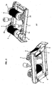
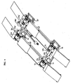
- the subset (A1) according to the figure 1 intended to receive a vehicle wheel, to be driven by it or to drive it in rotation comprises: a support frame (1) bearing known bearings (2a), (2b), (2c), (2d) allowing the rotation of 2 poly V pulleys, (3) and (4) coated with a poly V belt not shown.
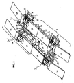
- the four subsets (A1), (A2) and (A1 '), (A2'), according to the figure 2 are intended to receive the wheels of the vehicle.
- Subassemblies (A1) and (A2) form an assembly (B) with the frame (9) fixed to the ground.
- the subset (A1) is fixed in translation
- the subset (A2) is connected to the sub together (A1) by a telescopic cardan joint transmission (10)
- the subassembly (A2) is secured to a support plate (11) which can translate and is guided laterally on the frame (9) by any known means.
- the cylinder (12) secured on one side to the frame (9) and on the other to the support plate (11) makes it possible to bring the subassembly (A2) closer to or away from the subassembly (A1) so that the distance between the two subsets (A1) and (A2) can be perfectly adjusted to the vehicle lane.
- the subassembly (A2) comprises on the outer axis of the pulley (3) a braking or locking system (13) for immobilizing the pulleys / belts in rotation, thereby allowing the vehicle to leave the vehicle. bench.
- Ramps (14) and (15) fixed to the ground allow the vehicle to access the device.
- the tracks (16) and (17) fixed to the ground comprise on the sides of the tracks (18) on which the moving tracks (19) and (20) each have two rollers (21).
- Said mobile tracks are integral with the movable frame (9 ') itself provided with 8 rollers (22) located on either side under the securing of the movable tracks (19) and (20) to the frame (9') and under the subjections of said frame to the movable ramps (23) and (24).
- the movable tracks (19) and (20), the movable frame (9 ') carrying the subsets (A1') and (A2 '), the movable ramps (23) and (24) therefore form a moving subassembly (M ) which can be moved away from or closer to the fixed subassembly (F) by means of the jack (25) or any other system, motorization, chains / gears, pinion / rack ... thus allowing the subsets (F) and (M) ) to be adjusted to the wheelbase of the vehicle.
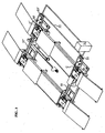
- the angle references (27) and (27 ') are secured to the support frames (1) and (1') so that they can follow the pivoting of the subsets (A1) and (A1 ').
- the shafts passing through said corner references (27) and (27 ') are connected by any known means to the shafts (5) and (5') and to the cardan joint telescopic transmissions (10) and (10 ').
- the shafts returning said angle returns (27) and (27 ') are interconnected by means of two transmissions with cardan joints (28) and (29) disengageable and at least one of which is telescopic so that the rotational movement of the belt pulleys / poly V systems of one of the subassemblies (A1), (A2), (A1 '), (A2') rotates at the same speed the other subassemblies thus eliminating the effects of differential between the left and right wheels and the front axle and the rear axle of the controlled vehicle.
- the rear wheels, not driving, in the case described figure are driven at the same speed by the front wheels
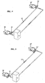
- the fluid contained in the reservoir (31) circulates in a pipe (32) partially flexible to adapt to the different displacements of the moving parts of the device.
- the fluid flow direction changes corresponding to different drive modes (traction or propulsion vehicle) are obtained by means of electrically controlled control valves (33) and (33 ').
- At least one coupler (C) or (C ') disengageable is interposed between the pulley shaft (5) or (5') and the pump shaft (30) or (30 ') so that, in the case of a traditional vehicle not requiring for its control the setting in movement of its two axles, only the front gear or only the rear train is in movement.
- a 4 * 4 vehicle, traction or propulsion modes can be indifferently selected.
- a reduction in the flow rate of the fluid in the driving gear pump (30) or (30 ') obtained by means of the regulating distributors (33) and (33') will make it possible to impose a quantized resisting torque on the driving wheels of the vehicle , so that a climb can be simulated and pollution controls in charge, carburettor settings and ignition can be operated thus saving the traditional test drive after intervention.
- a blocking mode closes the flow of fluid in the pumps (30) and (30 ') prohibiting the rotation of the gears of said pumps, so that the vehicle can leave the bench after its control.
- the shafts of the variable speed drives are connected to the shafts (5a), (5b), (5a '), (5b') to the known coupling means so that the wheels of a vehicle, engine running, speed to the point can be driven by the subsets (A1), (A2) and (A1 '), (A2') in rotation at the same speed.
- the shafts (5a), (5b) and (5a '), (5b') are provided with known torque-meters (35a), (35b), (35a '), (35b') and with the same characteristics, so that that: the resistant couples inflicted on each of the trees can be measured, compared with each other, recorded and printed by means of the electro-informatics group of known management, not shown
- the starting of the four motor-drives is triggered by the operator, when the desired speed of the four motor-drives is reached, the operator requests the braking system.
- the torque-meters detect the increase of the resistive couples transmit the information to the electro-computer subassembly which triggers the operations of measuring the couples and counting the encoders (6a), (6b) and (6a '), (6b' ) so that, in addition, the comparison of the left and right braking torques on the front and rear axles can be measured the distance necessary for the total immobilisation of the device and the wheels of the vehicle, taking into account the nominal speed motor-drives and the weight of said vehicle.
- variable speed drives continue to drive in rotation the subassemblies (A1), (A2), (A1 ') and (A2') thus simulating the parameterized inertia of the vehicle until, decreasing speed and resistant torques increase very rapidly, a relay cuts the power supply of the motor-dimmers so that, the resistive torque limit beyond which the wheels of the vehicle leave the device, is not reached .
Landscapes
- Physics & Mathematics (AREA)
- General Physics & Mathematics (AREA)
- Arrangement And Driving Of Transmission Devices (AREA)
- Electric Propulsion And Braking For Vehicles (AREA)
Claims (7)
- Vorrichtung zum Steuern, Einstellen und Messen der Räder eines Kraftfahrzeugs, Folgendes aufweisend:- vier Unterbaugruppen (A1, A2, A1', A2'), die dazu bestimmt sind, die vier Räder in Drehung des Fahrzeugs aufzunehmen,- Spuren (16, 17, 19, 20) und absteigende (23, 24) und aufsteigende Rampen (14, 15) zum Anbringen der Räder des Fahrzeugs auf den Unterbaugruppen (A1, A2, A1', A2'), wobei jede der Rampen (14, 15, 23, 24) mit einer Unterbaugruppe (A1, A2, A1', A2') derart verbunden werden kann, dass ein erstes Paar Unterbaugruppen (A1, A2) für die zwei Unterbaugruppen (A1, A2), die zu den aufsteigenden Rampen (14, 15) gehören, und ein zweites Paar Unterbaugruppen (A1', A2') für die zwei Unterbaugruppen (A1', A2'), die zu den absteigenden Rampen (23, 24) gehören, definiert werden können,- eine elektrisch-informatische Unterbaugruppe zur Verwaltung von Informationen, die von den Unterbaugruppen (A1, A2, A1', A2') kommen,wobei jede Unterbaugruppe (A1, A2, A1', A2') ein Tragchassis (1) aufweist, das Lager (2a, 2b, 2a', 2b') trägt, die das Drehen von zwei Rollen oder zwei Scheiben (3, 4) erlauben, die mit einem Riemen mit gleichem Profil oder mit gleichem Muster wie die Scheiben belegt sind, wobei das jeweilige Chassis (1), das von einem jeweils stationären (9) oder beweglichen Rahmen (9') getragen wird, eine Führungsbohrung (7) der Unterbaugruppe (A1, A2, A1', A2') um eine jeweilige Schwenkachse aufweist und Kugeln (8) aufweist, um das Schwenken der betreffenden Unterbaugruppe (A1, A2, A1', A2') um die dazugehörende Achse zu erleichtern,
wobei die Vorrichtung ferner- eine erste Umlenkung (27),- eine teleskopische Übertragung mit Verbindungskardangelenken (10) zwischen Abtriebswellen der Scheiben oder Rollen (3a, 3b) eines Paars von Unterbaugruppen (A1, A2),- eine zweite Umlenkung (27') mit gleichen Merkmalen wie die erste Umlenkung (27),- eine teleskopische Übertragung mit Verbindungskardangelenken (10') zwischen Abtriebswellen der Scheiben oder Rollen (3a', 3b') eines zweiten Paars der Unterbaugruppen (A1', A2'), und- zwei teleskopische Übertragungen mit ausrückbaren Verbindungskardangelenken (28, 29) zwischen Wellen, die die Umlenkungen (27, 27') umlenken, wobei die Umlenkungen (27, 27') mit den Abtriebswellen der Scheiben oder Rollen und den teleskopischen Übertragungen mit Kardangelenken (10, 10') verbunden sind. - Vorrichtung nach Anspruch 1, die zu beiden Seiten des stationären Rahmens (9) auf dem Boden und der das erste Paar Unterbaugruppen (A1, A2) trägt, stationäre Zugangsrampen auf dem Boden (14, 15) stationäre Spuren auf dem Boden (16, 17), die jeweils mit Rollbahnen (18) versehen sind, auf welchen die beweglichen Spuren (19, 20) laufen, die mit Rollen (21) versehen und mit dem beweglichen Rahmen auf dem Boden (9') der das zweite Paar Unterbaugruppen (A1', A2') trägt, und der selbst mit Verschiebungsrollen (22) versehen ist, verbunden sind, wobei der Rahmen (9') mit beweglichen Abstiegsrampen (23, 24) fest verbunden ist, und ein Antrieb (25) und ein Verschiebungsführer (26) erlauben es, den beweglichen Rahmen (9') dem stationären Rahmen (9) zu nähern oder von ihm zu beabstanden.
- Vorrichtung nach einem der Ansprüche 1 oder 2, die zwei Unterbaugruppen (A1, A1') aufweist, die in seitlicher Verschiebung auf dem stationären Rahmen (9) und auf dem beweglichen Rahmen (9') stationär sind, und zwei Unterbaugruppen (A2, A2'), die auf dem stationären Rahmen (9) und auf dem beweglichen Rahmen (9') seitlich beweglich sind, sowie zwei Antriebe (12, 12'), die es erlauben, die beweglichen Unterbaugruppen (A2, A2') der stationären Unterbaugruppen (A1, A1') zu nähern oder zu beabstanden.
- Vorrichtung nach einem der Ansprüche 1 bis 3, die Impulscodierer mit großer Auflösung (6a, 6b, 6a', 6b'), Drehmomentanzeiger (35a, 35b, 35a', 35b'), ausrückbare Kuppler (C, C'), Bremsen oder Blockierer (13), Verteiler-Regler (33, 33'), die fest auf die Abtriebswellen der Scheiben oder Rollen (3a, 3b, 3a', 3b') der Unterbaugruppen (A1, A2, A1', A2') montiert sind, zwei Antriebe zum Justieren auf die Spurweite (12, 12'), einen Antrieb zum Justieren auf den Radstand (25) aufweist, wobei alle diese verschiedenen Elemente mit der elektrisch-informatischen Unterbaugruppe zur Verwaltung durch Verbindungskabel verbunden sind.
- Vorrichtung nach einem der Ansprüche 1 oder 4, die Drehzahlwandler (34a, 34b, 34a', 34b') mit gleichen Merkmalen, die gesteuert und geregelt sind, deren Wellen mit den Abtriebswellen der Scheiben (3a, 3b, 3a', 3b') verbunden sind, die mit Codierern (6a, 6b, 6a', 6b') und Drehmomentanzeigern (35a, 35b, 35a', 35b') versehen sind, aufweist.
- Vorrichtung nach Anspruch 5, die die Stromversorgung der Drehzahlwandler (34a, 34b, 34a', 34b') mit Relais unterbrechen kann, kurz bevor bei einem Bremsen ein Grenzwiderstandsmoment, der das Fahrzeug aus der Vorrichtung austreten lassen würde, erreicht wird.
- Vorrichtung nach einem der vorhergehenden Ansprüche, wobei der untere Teil des Chassis die Führungsbohrung (7) einer Schwenkachse der Unterbaugruppe (A1, A2, A1', A2') derart aufweist, dass das Rad und der Riemen untereinander eine gemeinsame tangentiale Bewegungsrichtung behalten.
Applications Claiming Priority (1)
| Application Number | Priority Date | Filing Date | Title |
|---|---|---|---|
| PCT/FR2005/002674 WO2007048882A1 (fr) | 2005-10-26 | 2005-10-26 | Dispositif de controle prenant en compte les quatre roues en rotation d’un vehicule, sa voie et son empattement |
Publications (2)
| Publication Number | Publication Date |
|---|---|
| EP1946068A1 EP1946068A1 (de) | 2008-07-23 |
| EP1946068B1 true EP1946068B1 (de) | 2011-12-14 |
Family
ID=35654954
Family Applications (1)
| Application Number | Title | Priority Date | Filing Date |
|---|---|---|---|
| EP05815026A Expired - Lifetime EP1946068B1 (de) | 2005-10-26 | 2005-10-26 | Steuereinrichtung, die die vier sich drehenden Räder eines Fahrzeugs, seine Spurweite und seinen Radstand berücksichtigt |
Country Status (3)
| Country | Link |
|---|---|
| EP (1) | EP1946068B1 (de) |
| AT (1) | ATE537434T1 (de) |
| WO (1) | WO2007048882A1 (de) |
Families Citing this family (8)
| Publication number | Priority date | Publication date | Assignee | Title |
|---|---|---|---|---|
| FR2997500B1 (fr) * | 2012-10-29 | 2015-07-17 | Mi Systems | Banc d'essais pour vehicule automobile |
| CN103226067B (zh) * | 2013-04-22 | 2016-01-20 | 庞抗美 | 机动车模拟路试检测装置及检测方法 |
| FR3034193A1 (fr) * | 2015-03-24 | 2016-09-30 | Daniel Frederic Fuchs | Banc d'essais retractable pour vehicules |
| FR3056657A1 (fr) * | 2016-09-28 | 2018-03-30 | Rotronics | Transmission mecanique du mouvement de rotation et banc d'essai la comportant |
| CN112082776A (zh) * | 2020-09-30 | 2020-12-15 | 山东交通学院 | 一种带台体升降装置的无人驾驶汽车abs试验台 |
| CN113203574B (zh) * | 2021-03-30 | 2023-11-24 | 嘉兴逸合盛制冷科技有限公司 | 一种汽车配件中刹车检测装置 |
| DE102021129687A1 (de) * | 2021-11-15 | 2023-05-17 | Dürr Assembly Products GmbH | Verfahren zur Positionierung eines Fahrzeugs auf einem Fahrzeugprüfstand |
| FR3138694B1 (fr) * | 2022-08-02 | 2024-11-29 | Renault Sas | Système et procédé pour tester un véhicule. |
Citations (3)
| Publication number | Priority date | Publication date | Assignee | Title |
|---|---|---|---|---|
| US5269179A (en) * | 1991-11-18 | 1993-12-14 | Frank L. Wells Company | Vehicle testing apparatus |
| US5335537A (en) * | 1991-09-19 | 1994-08-09 | Honda Giken Kogyo Kabushiki Kaisha | Method of inspecting limited slip differential for vehicle |
| DE19529284C1 (de) * | 1995-08-09 | 1996-10-24 | Mc Micro Compact Car Ag | Adaption eines Einrollen-Kfz-Leistungsprüfstandes für allradgetriebene Fahrzeuge |
Family Cites Families (7)
| Publication number | Priority date | Publication date | Assignee | Title |
|---|---|---|---|---|
| ES8503848A1 (es) * | 1983-03-29 | 1985-03-01 | Lambrecht Willy | Procedimiento y aparato para probar o inspeccionar las ruedad de un vehiculo |
| JPS59180447A (ja) * | 1983-03-31 | 1984-10-13 | Agency Of Ind Science & Technol | 自動車シミユレ−タ |
| US5231870A (en) * | 1988-12-14 | 1993-08-03 | Anzen Motor Co., Ltd. | Vehicle composite test apparatus |
| US5111685A (en) * | 1989-12-20 | 1992-05-12 | Mts Systems Corporation | Roadway simulator restraint |
| JP2001030945A (ja) * | 1999-07-16 | 2001-02-06 | Bridgestone Corp | ホイールアライメント調整装置 |
| EP1482294B1 (de) * | 2002-03-04 | 2010-07-28 | Honda Giken Kogyo Kabushiki Kaisha | Vorrichtung und verfahren zum untersuchen eines motorrads |
| DE10333762B4 (de) * | 2003-07-24 | 2022-12-29 | Man Truck & Bus Se | Fahrzeugprüfstand |
-
2005
- 2005-10-26 EP EP05815026A patent/EP1946068B1/de not_active Expired - Lifetime
- 2005-10-26 AT AT05815026T patent/ATE537434T1/de active
- 2005-10-26 WO PCT/FR2005/002674 patent/WO2007048882A1/fr not_active Ceased
Patent Citations (3)
| Publication number | Priority date | Publication date | Assignee | Title |
|---|---|---|---|---|
| US5335537A (en) * | 1991-09-19 | 1994-08-09 | Honda Giken Kogyo Kabushiki Kaisha | Method of inspecting limited slip differential for vehicle |
| US5269179A (en) * | 1991-11-18 | 1993-12-14 | Frank L. Wells Company | Vehicle testing apparatus |
| DE19529284C1 (de) * | 1995-08-09 | 1996-10-24 | Mc Micro Compact Car Ag | Adaption eines Einrollen-Kfz-Leistungsprüfstandes für allradgetriebene Fahrzeuge |
Also Published As
| Publication number | Publication date |
|---|---|
| WO2007048882A1 (fr) | 2007-05-03 |
| ATE537434T1 (de) | 2011-12-15 |
| EP1946068A1 (de) | 2008-07-23 |
Similar Documents
| Publication | Publication Date | Title |
|---|---|---|
| EP1946068B1 (de) | Steuereinrichtung, die die vier sich drehenden Räder eines Fahrzeugs, seine Spurweite und seinen Radstand berücksichtigt | |
| FR2560564A1 (fr) | Suspension a roues independantes a bras oscillants pour vehicule a moteur | |
| FR2875906A1 (fr) | Dispositif de controle prenant en compte les quatre roues en rotation d'un vehicule, sa voie et son empattement | |
| FR2541217A1 (fr) | Commande de protection au pliage pour vehicules articules | |
| FR3100755B1 (fr) | Chaîne de transmission électrique pour véhicule automobile | |
| FR2949421A1 (fr) | Dispositif de controle de trajectoire pour vehicule etroit a motorisation electrique et inclinaison asservie | |
| FR2842302A1 (fr) | Dispositif et procede de simulation de glissement sur des bancs de test de vehicules | |
| BE1001564A4 (fr) | Procede et dispositif de regulation du couple moteur transmis par un tracteur a une semi-remorque a entrainement hydraulique. | |
| EP0208598B1 (de) | Schienengeführtes Fahrzeug mit Schwenkbaren Radachsen | |
| FR2523057A1 (fr) | Procede pour eviter le patinage ou glissement entre roues motrices et sol dans des systemes d'entrainement de vehicules du type a essieux multiples a transmission de puissance hydrostatique | |
| EP2354781B1 (de) | Vorrichtung zur bestimmung der haftreibung einer fahrbahn | |
| EP2614351B1 (de) | Testvorrichtung zur messung der von einem reifen getragenen lasten | |
| FR2473444A1 (fr) | Vehicule sans conducteur a came de commande de vitesse de convoyeur utilisant ce vehicule | |
| FR2671570A1 (fr) | Chargeur-escavateur avec grue operant aussi bien sur route que sur rail avec un chassis articule. | |
| FR2778612A1 (fr) | Procede d'alimentation electrique des moteurs des essieux avant et arriere d'un meme vehicule | |
| FR3108697A1 (fr) | Réducteur pour véhicule électrique ou hybride avec dispositifs d’amortissement pendulaire | |
| EP0000296B1 (de) | Antriebsvorrichtung für Kraftfahrzeuge insbes. für Hubstapler. | |
| JP2000155076A (ja) | シャシーダイナモメータ | |
| EP0297007B1 (de) | Vorrichtung zur Drehkraftabnahme an Kraftfahrzeugen | |
| JP2021160432A (ja) | 駆動機構及びこれを備えた車両搬送装置 | |
| FR2799162A1 (fr) | Systeme d'entrainement electrique d'un essieu de vehicule automoteur | |
| FR2691539A1 (fr) | Banc d'essai à rouleaux pour véhicules automobiles. | |
| US3872942A (en) | Earth-rolling vehicles | |
| EP4056448B1 (de) | Bedienungsvorrichtung in einem wagen eines schienenfahrzeugs | |
| US1212683A (en) | Transmission apparatus. |
Legal Events
| Date | Code | Title | Description |
|---|---|---|---|
| PUAI | Public reference made under article 153(3) epc to a published international application that has entered the european phase |
Free format text: ORIGINAL CODE: 0009012 |
|
| 17P | Request for examination filed |
Effective date: 20080526 |
|
| AK | Designated contracting states |
Kind code of ref document: A1 Designated state(s): AT BE BG CH CY CZ DE DK EE ES FI FR GB GR HU IE IS IT LI LT LU LV MC NL PL PT RO SE SI SK TR |
|
| 17Q | First examination report despatched |
Effective date: 20080922 |
|
| RIN1 | Information on inventor provided before grant (corrected) |
Inventor name: L'HELGOUARC'H, ALAIN Inventor name: CLAUDE, DURAND Inventor name: LA ROCCA, JEAN-PIERRE Inventor name: EDMOND, PURGUETTE |
|
| RAP1 | Party data changed (applicant data changed or rights of an application transferred) |
Owner name: DURAND, CLAUDE Owner name: L'HELGOUARC'H, ALAIN Owner name: PURGUETTE, EDMOND Owner name: LA ROCCA, JEAN PIERRE |
|
| RAP1 | Party data changed (applicant data changed or rights of an application transferred) |
Owner name: POLYTESTS INDUSTRIE |
|
| RIN1 | Information on inventor provided before grant (corrected) |
Inventor name: LA ROCCA, JEAN-PIERRE Inventor name: DURAND, CLAUDE Inventor name: PURGUETTE, EDMOND Inventor name: L'HELGOUARC'H, ALAIN |
|
| GRAP | Despatch of communication of intention to grant a patent |
Free format text: ORIGINAL CODE: EPIDOSNIGR1 |
|
| RTI1 | Title (correction) |
Free format text: CONTROL DEVICE TAKING INTO ACCOUNT THE FOUR ROTATING WHEELS OF A VEHICLE, ITS GAUGE AND ITS WHEELBASE |
|
| DAX | Request for extension of the european patent (deleted) | ||
| GRAS | Grant fee paid |
Free format text: ORIGINAL CODE: EPIDOSNIGR3 |
|
| GRAA | (expected) grant |
Free format text: ORIGINAL CODE: 0009210 |
|
| AK | Designated contracting states |
Kind code of ref document: B1 Designated state(s): AT BE BG CH CY CZ DE DK EE ES FI FR GB GR HU IE IS IT LI LT LU LV MC NL PL PT RO SE SI SK TR |
|
| REG | Reference to a national code |
Ref country code: GB Ref legal event code: FG4D Free format text: NOT ENGLISH |
|
| REG | Reference to a national code |
Ref country code: CH Ref legal event code: EP |
|
| REG | Reference to a national code |
Ref country code: IE Ref legal event code: FG4D |
|
| REG | Reference to a national code |
Ref country code: DE Ref legal event code: R096 Ref document number: 602005031698 Country of ref document: DE Effective date: 20120216 |
|
| REG | Reference to a national code |
Ref country code: NL Ref legal event code: VDEP Effective date: 20111214 |
|
| PG25 | Lapsed in a contracting state [announced via postgrant information from national office to epo] |
Ref country code: LT Free format text: LAPSE BECAUSE OF FAILURE TO SUBMIT A TRANSLATION OF THE DESCRIPTION OR TO PAY THE FEE WITHIN THE PRESCRIBED TIME-LIMIT Effective date: 20111214 |
|
| REG | Reference to a national code |
Ref country code: CH Ref legal event code: NV Representative=s name: R. A. EGLI & CO. PATENTANWAELTE |
|
| LTIE | Lt: invalidation of european patent or patent extension |
Effective date: 20111214 |
|
| PG25 | Lapsed in a contracting state [announced via postgrant information from national office to epo] |
Ref country code: SE Free format text: LAPSE BECAUSE OF FAILURE TO SUBMIT A TRANSLATION OF THE DESCRIPTION OR TO PAY THE FEE WITHIN THE PRESCRIBED TIME-LIMIT Effective date: 20111214 Ref country code: LV Free format text: LAPSE BECAUSE OF FAILURE TO SUBMIT A TRANSLATION OF THE DESCRIPTION OR TO PAY THE FEE WITHIN THE PRESCRIBED TIME-LIMIT Effective date: 20111214 Ref country code: NL Free format text: LAPSE BECAUSE OF FAILURE TO SUBMIT A TRANSLATION OF THE DESCRIPTION OR TO PAY THE FEE WITHIN THE PRESCRIBED TIME-LIMIT Effective date: 20111214 Ref country code: GR Free format text: LAPSE BECAUSE OF FAILURE TO SUBMIT A TRANSLATION OF THE DESCRIPTION OR TO PAY THE FEE WITHIN THE PRESCRIBED TIME-LIMIT Effective date: 20120315 Ref country code: SI Free format text: LAPSE BECAUSE OF FAILURE TO SUBMIT A TRANSLATION OF THE DESCRIPTION OR TO PAY THE FEE WITHIN THE PRESCRIBED TIME-LIMIT Effective date: 20111214 |
|
| PG25 | Lapsed in a contracting state [announced via postgrant information from national office to epo] |
Ref country code: CY Free format text: LAPSE BECAUSE OF FAILURE TO SUBMIT A TRANSLATION OF THE DESCRIPTION OR TO PAY THE FEE WITHIN THE PRESCRIBED TIME-LIMIT Effective date: 20111214 |
|
| REG | Reference to a national code |
Ref country code: IE Ref legal event code: FD4D |
|
| PG25 | Lapsed in a contracting state [announced via postgrant information from national office to epo] |
Ref country code: BG Free format text: LAPSE BECAUSE OF FAILURE TO SUBMIT A TRANSLATION OF THE DESCRIPTION OR TO PAY THE FEE WITHIN THE PRESCRIBED TIME-LIMIT Effective date: 20120314 Ref country code: EE Free format text: LAPSE BECAUSE OF FAILURE TO SUBMIT A TRANSLATION OF THE DESCRIPTION OR TO PAY THE FEE WITHIN THE PRESCRIBED TIME-LIMIT Effective date: 20111214 Ref country code: CZ Free format text: LAPSE BECAUSE OF FAILURE TO SUBMIT A TRANSLATION OF THE DESCRIPTION OR TO PAY THE FEE WITHIN THE PRESCRIBED TIME-LIMIT Effective date: 20111214 Ref country code: IE Free format text: LAPSE BECAUSE OF FAILURE TO SUBMIT A TRANSLATION OF THE DESCRIPTION OR TO PAY THE FEE WITHIN THE PRESCRIBED TIME-LIMIT Effective date: 20111214 Ref country code: IS Free format text: LAPSE BECAUSE OF FAILURE TO SUBMIT A TRANSLATION OF THE DESCRIPTION OR TO PAY THE FEE WITHIN THE PRESCRIBED TIME-LIMIT Effective date: 20120414 Ref country code: SK Free format text: LAPSE BECAUSE OF FAILURE TO SUBMIT A TRANSLATION OF THE DESCRIPTION OR TO PAY THE FEE WITHIN THE PRESCRIBED TIME-LIMIT Effective date: 20111214 |
|
| PG25 | Lapsed in a contracting state [announced via postgrant information from national office to epo] |
Ref country code: RO Free format text: LAPSE BECAUSE OF FAILURE TO SUBMIT A TRANSLATION OF THE DESCRIPTION OR TO PAY THE FEE WITHIN THE PRESCRIBED TIME-LIMIT Effective date: 20111214 Ref country code: PL Free format text: LAPSE BECAUSE OF FAILURE TO SUBMIT A TRANSLATION OF THE DESCRIPTION OR TO PAY THE FEE WITHIN THE PRESCRIBED TIME-LIMIT Effective date: 20111214 Ref country code: PT Free format text: LAPSE BECAUSE OF FAILURE TO SUBMIT A TRANSLATION OF THE DESCRIPTION OR TO PAY THE FEE WITHIN THE PRESCRIBED TIME-LIMIT Effective date: 20120416 |
|
| REG | Reference to a national code |
Ref country code: AT Ref legal event code: MK05 Ref document number: 537434 Country of ref document: AT Kind code of ref document: T Effective date: 20111214 |
|
| PLBE | No opposition filed within time limit |
Free format text: ORIGINAL CODE: 0009261 |
|
| STAA | Information on the status of an ep patent application or granted ep patent |
Free format text: STATUS: NO OPPOSITION FILED WITHIN TIME LIMIT |
|
| PG25 | Lapsed in a contracting state [announced via postgrant information from national office to epo] |
Ref country code: DK Free format text: LAPSE BECAUSE OF FAILURE TO SUBMIT A TRANSLATION OF THE DESCRIPTION OR TO PAY THE FEE WITHIN THE PRESCRIBED TIME-LIMIT Effective date: 20111214 |
|
| 26N | No opposition filed |
Effective date: 20120917 |
|
| REG | Reference to a national code |
Ref country code: DE Ref legal event code: R097 Ref document number: 602005031698 Country of ref document: DE Effective date: 20120917 |
|
| PG25 | Lapsed in a contracting state [announced via postgrant information from national office to epo] |
Ref country code: AT Free format text: LAPSE BECAUSE OF FAILURE TO SUBMIT A TRANSLATION OF THE DESCRIPTION OR TO PAY THE FEE WITHIN THE PRESCRIBED TIME-LIMIT Effective date: 20111214 |
|
| PG25 | Lapsed in a contracting state [announced via postgrant information from national office to epo] |
Ref country code: ES Free format text: LAPSE BECAUSE OF FAILURE TO SUBMIT A TRANSLATION OF THE DESCRIPTION OR TO PAY THE FEE WITHIN THE PRESCRIBED TIME-LIMIT Effective date: 20120325 |
|
| PG25 | Lapsed in a contracting state [announced via postgrant information from national office to epo] |
Ref country code: MC Free format text: LAPSE BECAUSE OF NON-PAYMENT OF DUE FEES Effective date: 20121031 |
|
| PG25 | Lapsed in a contracting state [announced via postgrant information from national office to epo] |
Ref country code: FI Free format text: LAPSE BECAUSE OF FAILURE TO SUBMIT A TRANSLATION OF THE DESCRIPTION OR TO PAY THE FEE WITHIN THE PRESCRIBED TIME-LIMIT Effective date: 20111214 |
|
| PG25 | Lapsed in a contracting state [announced via postgrant information from national office to epo] |
Ref country code: TR Free format text: LAPSE BECAUSE OF FAILURE TO SUBMIT A TRANSLATION OF THE DESCRIPTION OR TO PAY THE FEE WITHIN THE PRESCRIBED TIME-LIMIT Effective date: 20111214 |
|
| PG25 | Lapsed in a contracting state [announced via postgrant information from national office to epo] |
Ref country code: LU Free format text: LAPSE BECAUSE OF NON-PAYMENT OF DUE FEES Effective date: 20121026 |
|
| PG25 | Lapsed in a contracting state [announced via postgrant information from national office to epo] |
Ref country code: HU Free format text: LAPSE BECAUSE OF FAILURE TO SUBMIT A TRANSLATION OF THE DESCRIPTION OR TO PAY THE FEE WITHIN THE PRESCRIBED TIME-LIMIT Effective date: 20051026 |
|
| REG | Reference to a national code |
Ref country code: FR Ref legal event code: PLFP Year of fee payment: 11 |
|
| PGFP | Annual fee paid to national office [announced via postgrant information from national office to epo] |
Ref country code: GB Payment date: 20160428 Year of fee payment: 11 Ref country code: CH Payment date: 20160428 Year of fee payment: 11 Ref country code: DE Payment date: 20160429 Year of fee payment: 11 |
|
| PGFP | Annual fee paid to national office [announced via postgrant information from national office to epo] |
Ref country code: IT Payment date: 20160428 Year of fee payment: 11 Ref country code: BE Payment date: 20160428 Year of fee payment: 11 |
|
| PG25 | Lapsed in a contracting state [announced via postgrant information from national office to epo] |
Ref country code: BE Free format text: LAPSE BECAUSE OF NON-PAYMENT OF DUE FEES Effective date: 20161031 |
|
| REG | Reference to a national code |
Ref country code: FR Ref legal event code: PLFP Year of fee payment: 12 |
|
| REG | Reference to a national code |
Ref country code: DE Ref legal event code: R119 Ref document number: 602005031698 Country of ref document: DE |
|
| REG | Reference to a national code |
Ref country code: CH Ref legal event code: PL |
|
| GBPC | Gb: european patent ceased through non-payment of renewal fee |
Effective date: 20161026 |
|
| PG25 | Lapsed in a contracting state [announced via postgrant information from national office to epo] |
Ref country code: LI Free format text: LAPSE BECAUSE OF NON-PAYMENT OF DUE FEES Effective date: 20161031 Ref country code: GB Free format text: LAPSE BECAUSE OF NON-PAYMENT OF DUE FEES Effective date: 20161026 Ref country code: DE Free format text: LAPSE BECAUSE OF NON-PAYMENT OF DUE FEES Effective date: 20170503 Ref country code: CH Free format text: LAPSE BECAUSE OF NON-PAYMENT OF DUE FEES Effective date: 20161031 |
|
| PG25 | Lapsed in a contracting state [announced via postgrant information from national office to epo] |
Ref country code: IT Free format text: LAPSE BECAUSE OF NON-PAYMENT OF DUE FEES Effective date: 20161026 |
|
| REG | Reference to a national code |
Ref country code: FR Ref legal event code: PLFP Year of fee payment: 13 |
|
| REG | Reference to a national code |
Ref country code: BE Ref legal event code: MM Effective date: 20161031 |
|
| PGFP | Annual fee paid to national office [announced via postgrant information from national office to epo] |
Ref country code: FR Payment date: 20190219 Year of fee payment: 14 |
|
| PG25 | Lapsed in a contracting state [announced via postgrant information from national office to epo] |
Ref country code: FR Free format text: LAPSE BECAUSE OF NON-PAYMENT OF DUE FEES Effective date: 20191031 |