EP1947308A1 - Système de refroidissement de moteur intégré - Google Patents
Système de refroidissement de moteur intégré Download PDFInfo
- Publication number
- EP1947308A1 EP1947308A1 EP07100654A EP07100654A EP1947308A1 EP 1947308 A1 EP1947308 A1 EP 1947308A1 EP 07100654 A EP07100654 A EP 07100654A EP 07100654 A EP07100654 A EP 07100654A EP 1947308 A1 EP1947308 A1 EP 1947308A1
- Authority
- EP
- European Patent Office
- Prior art keywords
- coolant
- phase
- internal combustion
- combustion engine
- cylinder head
- Prior art date
- Legal status (The legal status is an assumption and is not a legal conclusion. Google has not performed a legal analysis and makes no representation as to the accuracy of the status listed.)
- Granted
Links
Images




Classifications
-
- F—MECHANICAL ENGINEERING; LIGHTING; HEATING; WEAPONS; BLASTING
- F01—MACHINES OR ENGINES IN GENERAL; ENGINE PLANTS IN GENERAL; STEAM ENGINES
- F01P—COOLING OF MACHINES OR ENGINES IN GENERAL; COOLING OF INTERNAL-COMBUSTION ENGINES
- F01P7/00—Controlling of coolant flow
- F01P7/14—Controlling of coolant flow the coolant being liquid
- F01P7/16—Controlling of coolant flow the coolant being liquid by thermostatic control
- F01P7/165—Controlling of coolant flow the coolant being liquid by thermostatic control characterised by systems with two or more loops
-
- F—MECHANICAL ENGINEERING; LIGHTING; HEATING; WEAPONS; BLASTING
- F01—MACHINES OR ENGINES IN GENERAL; ENGINE PLANTS IN GENERAL; STEAM ENGINES
- F01P—COOLING OF MACHINES OR ENGINES IN GENERAL; COOLING OF INTERNAL-COMBUSTION ENGINES
- F01P3/00—Liquid cooling
- F01P3/02—Arrangements for cooling cylinders or cylinder heads
-
- F—MECHANICAL ENGINEERING; LIGHTING; HEATING; WEAPONS; BLASTING
- F01—MACHINES OR ENGINES IN GENERAL; ENGINE PLANTS IN GENERAL; STEAM ENGINES
- F01P—COOLING OF MACHINES OR ENGINES IN GENERAL; COOLING OF INTERNAL-COMBUSTION ENGINES
- F01P3/00—Liquid cooling
- F01P3/02—Arrangements for cooling cylinders or cylinder heads
- F01P2003/024—Cooling cylinder heads
-
- F—MECHANICAL ENGINEERING; LIGHTING; HEATING; WEAPONS; BLASTING
- F01—MACHINES OR ENGINES IN GENERAL; ENGINE PLANTS IN GENERAL; STEAM ENGINES
- F01P—COOLING OF MACHINES OR ENGINES IN GENERAL; COOLING OF INTERNAL-COMBUSTION ENGINES
- F01P3/00—Liquid cooling
- F01P3/02—Arrangements for cooling cylinders or cylinder heads
- F01P2003/027—Cooling cylinders and cylinder heads in parallel
-
- F—MECHANICAL ENGINEERING; LIGHTING; HEATING; WEAPONS; BLASTING
- F01—MACHINES OR ENGINES IN GENERAL; ENGINE PLANTS IN GENERAL; STEAM ENGINES
- F01P—COOLING OF MACHINES OR ENGINES IN GENERAL; COOLING OF INTERNAL-COMBUSTION ENGINES
- F01P2037/00—Controlling
- F01P2037/02—Controlling starting
-
- F—MECHANICAL ENGINEERING; LIGHTING; HEATING; WEAPONS; BLASTING
- F01—MACHINES OR ENGINES IN GENERAL; ENGINE PLANTS IN GENERAL; STEAM ENGINES
- F01P—COOLING OF MACHINES OR ENGINES IN GENERAL; COOLING OF INTERNAL-COMBUSTION ENGINES
- F01P2060/00—Cooling circuits using auxiliaries
- F01P2060/16—Outlet manifold
Definitions
- the invention relates to a cooling strategy for an internal combustion engine having at least one cylinder head and an associated cylinder block, wherein a coolant flows in a coolant circuit, and wherein at least one control element is associated with the coolant circuit.
- the EP 1 375 857 A discloses a cooling device for an internal combustion engine.
- the cooling device has a plurality of cooling cells in a cylinder head, which are separated from each other and can be traversed by a cooling liquid.
- the cooling device further comprises at least first and second means for controlling the flow rate, the means being connected to at least one first cooling cell of the cylinder head and to at least one second cooling cell of the cylinder head.
- the first and second means are capable of controlling the amount of cooling liquid flowing through each first cooling cell and each second cooling cell, respectively.
- the invention has for its object to improve a cooling strategy of the type mentioned by simple means to the extent that friction losses are minimized, the engine can be performed as quickly as possible to the required operating temperature.
- the object is achieved by a cooling strategy with the features of claim 1, wherein the coolant flow is controlled during a warm-up phase of the internal combustion engine in successive phases by means of at least one control to separate cooling areas, and that the coolant flow in an adjoining operation at operating temperature of the internal combustion engine is controlled by means of the controls, taking into account operating conditions of the internal combustion engine to separate cooling areas.
- the invention is based on the finding that cooling water jackets have the main function to dissipate the heat resulting from the combustion, wherein the cooling water jackets should be designed such that the temperature distribution is homogeneous. It is therefore predominantly provided for the full load operation in which a maximum temperature, provided that the cooling water jacket is designed for this operating condition.
- both the advantages of good oil heating, exhaust gas warming, engine warming and passenger compartment warming can be achieved in the warm-up phase of the internal combustion engine, as well as good cooling of the warm engine.
- the coolant in a first phase of the warm-up phase, has a flow amount of zero, wherein the corresponding first control element is closed.
- the control can be designed for example as a mechanical or electromechanical valve or electrically heated thermostat, which is controlled by the exhaust gas temperature.
- the exhaust gas temperature Immediately after starting the internal combustion engine, the exhaust gas temperature has not yet the preferred amount of temperature, so that the valve first, preferably for a few seconds, is closed, so that a flow of coolant is first interrupted.
- the preferred temperature for keeping this valve closed may be based on the operating temperature of the catalyst coupled, and for example, an amount of less than 500 ° C (catalyst function start temperature) of the exhaust gas temperature.
- the valve opens, so that it is conveniently provided that in a second phase of the warm-up phase exhaust ports and exhaust manifold are cooled so that the coolant flow through an exhaust side of the cylinder head to a heating heat exchanger (heating) can flow.
- a heating heat exchanger heating
- a third phase of the warm-up phase exhaust ports and exhaust manifold and the cylinder block is cooled, wherein the exhaust control element or the valve and a third control, or a block thermostat are opened, so that the coolant through the Exhaust side of the cylinder head and the cylinder block flows to the heater.
- the exhaust control or the valve, a second control, or a thermostat and the third control element or the block thermostat are opened, so that the coolant through a Exhaust side of the cylinder head, and flows through the inlet side and through the cylinder block to the heater.
- Phase 5 When the engine is warm (Phase 5), it is contemplated that, in addition to the coolant flow through the heater described in Phase 4, coolant will flow through a radiator and surge tank.
- a conventional thermostat or a map controlled valve (map thermostat) can be provided as a fourth control.
- the exemplary four control elements are preferably arranged one behind the other, wherein the respective successive control elements are connected to each other via connecting lines.
- cooling strategies can be used depending on the operating state of the internal combustion engine.
- the entire internal combustion engine is cooled, wherein the coolant flows through the exhaust side of the cylinder head and through its inlet side and through the cylinder block to the heater core, to the radiator and to a surge tank.
- the exhaust gas control element is preferably controlled by the exhaust gas temperature.
- the valve preferably opens when an operating temperature of the catalytic converter is reached, which can already be the case after a few seconds after starting the internal combustion engine.
- the corresponding controls are controlled via the coolant temperature, which is why the corresponding controls are designed as a thermostat, preferably as a single-acting thermostat.
- the coolant temperature in the second phase is preferably less than 50 ° C, wherein the coolant temperature in the third phase may have an amount between 50 to 80 ° C and wherein in the fourth phase, a coolant temperature between 80 to 110 ° C may be present.
- the engine has reached its operating temperature.
- the coolant temperature is controlled between 80 ° C (full load) and 110 ° C (part load) depending on the engine operating point.
- the exemplified temperatures or temperature ranges are not to be regarded as limited to these, but may also have other amounts.
- a control of an exhaust side of the cylinder head, an inlet side of the cylinder head and the cylinder block is assigned, with another control or thermostat map can be controlled (map thermostat), the controls are controlled separately, so that in a warm-up phase of the internal combustion engine and in a subsequent operation under operating temperature separately selectable cooling regions can be flowed through by the coolant.
- the coolant circuit has a cylinder block water jacket and a cylinder head water jacket, which is divided into an inlet-side water jacket and an exhaust-side water jacket, a so-called “split cooling system” (separate coolant circuit, cylinder head), wherein the coolant circuit a coolant distributor can be assigned.
- split cooling system split coolant circuit, cylinder head
- an integrated and flexible thermal management system for an internal combustion engine in which heat flow from a heat source to a heat sink within the engine and the motor vehicle or any other application depends on the operating conditions of the internal combustion engine and the respective requirement of the vehicle occupant.
- This includes, inter alia, the function of a cooling system and additional special cooling areas, in which z. B. a heat flow should be avoided as long as the engine is cold. This corresponds for example to the first phase of the warm-up phase of the internal combustion engine, in which no coolant flows.
- a heat flow is achieved directly in the passenger compartment as soon and effectively as possible.
- the cooling zones can be divided by themselves, with the "split-cooling system" (separate coolant circuit, cylinder head) in particular being intended here.
- a faster warming of the internal combustion engine is achieved, whereby at the same time harmful emissions to the Environment be reduced.
- friction losses are minimized and fuel consumption thereby improved.
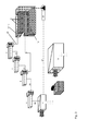
- FIG. 1 shows a cooling strategy for an internal combustion engine 1, which has at least one cylinder head 2 and an associated cylinder block 3.
- a coolant flows into a coolant circuit 4, wherein the coolant circuit 4 at least one control, in the illustrated embodiment, four control elements 6, 7, 8 and 9 are assigned.
- the internal combustion engine 1 is assigned a coolant distributor 11, through which the coolant flows into a cylinder block water jacket 12 (FIG. FIG. 3 ) and into a cylinder head water jacket 13 ( FIG. 4 ) flowing into an exhaust side 14 and into an inlet side 16 (FIG. FIG. 4 ) is split (split-cooling system, separate coolant circuit).
- the coolant circuit 4 further includes a heater 17 (heater core), a surge tank 18, a radiator 19, and a pump 21.
- the exhaust side 14 of the cylinder head water jacket 13 is associated with a first control element 6, which is designed as an electrically operable valve.
- the inlet side 16 of the cylinder head water jacket 13 is associated with a second control element 7, which is designed as a thermostat.
- the cylinder block water jacket 12 is associated with a third control, which is designed as a thermostat (block thermostat).
- a map thermostat 9 is assigned as the fourth control in the internal combustion engine 1.
- FIG. 1 a first phase of a warm-up phase of the internal combustion engine 1 is shown.
- the internal combustion engine is in a state immediately after its start.
- All controls 6 to 9, in particular the valve 6 are closed, so that no coolant circulates in the coolant circuit 4.
- the valve 6 is controlled by an exhaust gas temperature, wherein the interruption of the coolant circulation improved and faster heating of a catalyst, not shown, and the oil heating is achieved.
- the interruption of the coolant flow in the coolant circuit 4 is represented by the connecting lines shown in dashed lines, wherein the coolant flow has a magnitude of zero.
- the first phase of the warm-up phase of the internal combustion engine 1 is an improved heating of the structure of the internal combustion engine 1, in particular a improved oil heating achieved. On a warm-up of the passenger compartment, this first phase has no effect. At the same time low thermal losses are achieved both in the combustion chamber of the engine and on the exhaust side.
- the valve 6 opens (FIG. FIG. 2 ), so that the coolant flows through the exhaust side 14 of the cylinder head water jacket 13 to the heater 17.
- FIG. 2 illustrated second phase of the warm-up phase of the internal combustion engine 1 exhaust ports and exhaust manifolds are cooled.
- the valve 6 is connected to the thermostat 7 via a connecting line 22, wherein the thermostat 7 is connected via a connecting line 23 to the block thermostat 8, which is connected via a connecting line 24 to the map thermostat 9.
- the map thermostat 9 is connected via a connecting line 26 to the heater 17, which in turn is connected to a connecting line 27 to the pump 21, which transports the coolant via a connecting line 28 to the coolant manifold 11.
- the exhaust side 14 of the cylinder head water jacket 13 is connected via a connecting line 29 to the valve 6.
- the exhaust ports and exhaust manifold are cooled, so that the heater 17, the necessary energy is provided.
- a heat transfer is achieved in the coolant, where the majority of the heat is generated.
- low thermal losses are achieved in the combustion chamber of the internal combustion engine.
- FIG. 3 is a third phase of the warm-up phase of the internal combustion engine 1 is shown, wherein the valve 6 and the block thermostat 8 are opened.
- the coolant can flow through the exhaust side 14 of the cylinder head 13 and through the cylinder block 3 or through the cylinder head water jacket 13 to the heater 17.
- the cylinder block water jacket 12 is connected via a connecting line 31 directly to the block thermostat 8.
- the exhaust ports and exhaust manifold and the cylinder block 3 are cooled.
- the thermally critical areas are cooled, wherein the heat transfer is achieved in the coolant where heat is generated.
- the two cooling areas exhaust gas side 14, cylinder block water jacket 12 are connected in parallel.
- FIG. 4 a fourth phase of the warm-up phase of the internal combustion engine 1 is shown, in which the entire internal combustion engine flows through and is cooled.
- the valve 6, the thermostat 7 and the block thermostat 8 are opened, so that the coolant through the exhaust side 14 of the cylinder head water jacket 13 and through its inlet side 16 and through the cylinder block or by the cylinder block water jacket 12 to the heater 17 (by the closed map thermostat ) flows.
- the inlet side 16 of the cylinder head water jacket 13 is connected via a connecting line 32 to the thermostat 7.
- a fifth phase (operationally warm engine) is provided that the coolant flows through the map thermostat 9 via a connecting line to the radiator 19, which is connected to the connecting line 27 from the heater 17 to the pump 21.
- the coolant flows through the surge tank 18, which may be connected to the map thermostat 9 via a connecting line, the surge tank 18 may be connected via a further connecting line to the connecting line 27 from the heater 17 to the pump 21.
- FIG. 5 is the cooling strategy for the operating warm combustion engine 1 shown under full load.
- the entire internal combustion engine 1 is cooled, wherein the coolant flows through the exhaust side 14 of the cylinder head water jacket 13 and through its inlet side 16 and through the cylinder block or cylinder block water jacket 12 to the heater 17, to the radiator 19, and to a surge tank 18.
- the map thermostat 9 is connected via a connecting line 33 to the radiator 19, which in turn opens via a connecting line 34 into the connecting line 27 from the heater 17 to the pump 11.
- From the connecting line 33 branches off a connecting line 36 to the surge tank 18, which in turn is connected via a connecting line 37 to the connecting line 27 from the heater 17 to the pump 21.
- valve 6 can be omitted if the pump 21 or the coolant pump in the coolant circuit 4 is replaced by a controllable coolant pump with zero delivery option.
- a cooling strategy for a partial load operation of the internal combustion engine at operating temperature in which the exhaust side 14 of the cylinder head water jacket 13 and the cylinder block 3 and the cylinder head water jacket 13 is cooled, the coolant through the exhaust side 14 of the cylinder head water jacket 13 and through the cylinder block 3 and flows through the cylinder block water jacket 12 to the heater 17.
Landscapes
- Engineering & Computer Science (AREA)
- Chemical & Material Sciences (AREA)
- Combustion & Propulsion (AREA)
- Mechanical Engineering (AREA)
- General Engineering & Computer Science (AREA)
- Exhaust Gas After Treatment (AREA)
- Cylinder Crankcases Of Internal Combustion Engines (AREA)
Priority Applications (3)
| Application Number | Priority Date | Filing Date | Title |
|---|---|---|---|
| DE502007001624T DE502007001624D1 (de) | 2007-01-17 | 2007-01-17 | Integriertes Motorkühlsystem |
| EP07100654A EP1947308B1 (fr) | 2007-01-17 | 2007-01-17 | Système de refroidissement de moteur intégré |
| US12/015,743 US7721683B2 (en) | 2007-01-17 | 2008-01-17 | Integrated engine thermal management |
Applications Claiming Priority (1)
| Application Number | Priority Date | Filing Date | Title |
|---|---|---|---|
| EP07100654A EP1947308B1 (fr) | 2007-01-17 | 2007-01-17 | Système de refroidissement de moteur intégré |
Publications (2)
| Publication Number | Publication Date |
|---|---|
| EP1947308A1 true EP1947308A1 (fr) | 2008-07-23 |
| EP1947308B1 EP1947308B1 (fr) | 2009-09-30 |
Family
ID=38171592
Family Applications (1)
| Application Number | Title | Priority Date | Filing Date |
|---|---|---|---|
| EP07100654A Ceased EP1947308B1 (fr) | 2007-01-17 | 2007-01-17 | Système de refroidissement de moteur intégré |
Country Status (3)
| Country | Link |
|---|---|
| US (1) | US7721683B2 (fr) |
| EP (1) | EP1947308B1 (fr) |
| DE (1) | DE502007001624D1 (fr) |
Cited By (13)
| Publication number | Priority date | Publication date | Assignee | Title |
|---|---|---|---|---|
| DE102008035955A1 (de) * | 2008-07-31 | 2010-03-11 | Ford Global Technologies, LLC, Dearborn | Kühlstrategie |
| DE102010018624A1 (de) * | 2010-04-28 | 2011-11-03 | Audi Ag | Kühlmittelkreislauf für eine Brennkraftmaschine |
| DE102010045217A1 (de) * | 2010-09-13 | 2012-03-15 | Audi Ag | Kühlmittelkreislauf für eine Brennkraftmaschine |
| EP2375025A3 (fr) * | 2010-03-08 | 2013-04-17 | Audi AG | Circuit de refroidissement pour moteur à combustion interne |
| US8757110B2 (en) | 2009-05-06 | 2014-06-24 | Audi Ag | Coolant circuit |
| US9212620B2 (en) | 2010-02-18 | 2015-12-15 | Ford Global Technologies, Llc | Coolant jackets for an internal combustion engine and method of control |
| CN106368764A (zh) * | 2015-07-21 | 2017-02-01 | 通用汽车环球科技运作有限责任公司 | 用于从发动机油去除燃料的系统和方法 |
| DE102015121632A1 (de) | 2015-12-11 | 2017-06-14 | Dr. Ing. H.C. F. Porsche Aktiengesellschaft | Verfahren zum Kühlen einer Brennkraftmaschine |
| DE102016215310A1 (de) * | 2016-08-17 | 2018-02-22 | Bayerische Motoren Werke Aktiengesellschaft | Verfahren zur Kühlung einer Hubkolbenmaschine, Computerprogrammprodukt und Motor |
| DE102018104099A1 (de) * | 2018-02-23 | 2019-08-29 | Volkswagen Aktiengesellschaft | Brennkraftmaschine und Kraftfahrzeug |
| DE102018104105A1 (de) * | 2018-02-23 | 2019-08-29 | Volkswagen Aktiengesellschaft | Brennkraftmaschine und Kraftfahrzeug |
| EP3800335A1 (fr) * | 2019-10-01 | 2021-04-07 | FPT Industrial S.p.A. | Moteur à combustion interne pourvu d'un système de refroidissement par liquide |
| DE102015109145B4 (de) | 2014-10-29 | 2022-01-13 | Hyundai Motor Company | Verbrennungsmotorsystem mit Kühlmittel-Steuerventil |
Families Citing this family (19)
| Publication number | Priority date | Publication date | Assignee | Title |
|---|---|---|---|---|
| DE102008037062A1 (de) * | 2008-08-08 | 2010-02-11 | Bayerische Motoren Werke Aktiengesellschaft | Kühleinrichtung für eine Kraftfahrzeug-Brennkraftmaschine und Verfahren zum Betreiben derselben |
| DE102008059613B4 (de) * | 2008-11-28 | 2010-12-30 | Itw Automotive Products Gmbh | Kühlsystem für einen Verbrennungsmotor |
| AT508801B1 (de) * | 2009-10-07 | 2011-09-15 | Ge Jenbacher Gmbh & Co Ohg | Brennkraftmaschinenzündvorrichtung |
| DE102010060319B4 (de) * | 2010-11-03 | 2012-05-31 | Ford Global Technologies, Llc. | Kühlsystem |
| CN103261616B (zh) * | 2010-12-13 | 2015-04-01 | 丰田自动车株式会社 | 发动机的冷却装置 |
| JP5582133B2 (ja) * | 2011-12-22 | 2014-09-03 | 株式会社デンソー | エンジン冷却液循環システム |
| JP5919031B2 (ja) * | 2012-02-28 | 2016-05-18 | 株式会社ミクニ | 冷却水制御バルブ装置 |
| US8997483B2 (en) * | 2012-05-21 | 2015-04-07 | GM Global Technology Operations LLC | Engine thermal management system and method for split cooling and integrated exhaust manifold applications |
| US9103351B2 (en) * | 2012-10-09 | 2015-08-11 | GM Global Technology Operations LLC | Cooling pump for a cooling system |
| GB2519167A (en) * | 2013-10-14 | 2015-04-15 | Gm Global Tech Operations Inc | Cooling system for an internal combustion engine |
| JP6127950B2 (ja) * | 2013-12-09 | 2017-05-17 | マツダ株式会社 | エンジンの冷却構造 |
| JP6123660B2 (ja) * | 2013-12-09 | 2017-05-10 | マツダ株式会社 | エンジンの冷却構造 |
| JP6135684B2 (ja) * | 2015-01-26 | 2017-05-31 | マツダ株式会社 | エンジンの冷却装置 |
| DE102015201238B3 (de) * | 2015-01-26 | 2016-05-12 | Ford Global Technologies, Llc | Verfahren zum Betrieb einer Brennkraftmaschine mit Split-Kühlsystem und Zylinderabschaltung |
| DE202015100550U1 (de) * | 2015-02-05 | 2016-05-09 | Bürkert Werke GmbH | Prozessventilinsel und Wärmetauschersystem |
| DE102015009501A1 (de) | 2015-07-22 | 2017-01-26 | GM Global Technology Operations LLC (n. d. Ges. d. Staates Delaware) | Brennkraftmaschinenkühlung |
| US10215080B2 (en) * | 2016-11-01 | 2019-02-26 | Ford Global Technologies, Llc | Systems and methods for rapid engine coolant warmup |
| KR102383230B1 (ko) * | 2016-12-13 | 2022-04-05 | 현대자동차 주식회사 | 엔진 냉각 시스템 |
| DE102023125886A1 (de) | 2023-09-25 | 2025-03-27 | Bayerische Motoren Werke Aktiengesellschaft | Verfahren zum Betreiben einer Verbrennungskraftmaschine eines Kraftfahrzeugs sowie Verbrennungskraftmaschine |
Citations (4)
| Publication number | Priority date | Publication date | Assignee | Title |
|---|---|---|---|---|
| JPH08218873A (ja) * | 1995-02-09 | 1996-08-27 | Toyota Motor Corp | 内燃機関の冷却装置 |
| EP1375857A1 (fr) * | 2002-06-27 | 2004-01-02 | Renault s.a.s. | Dispositif de refroidissement pour moteur à combustion |
| FR2855555A1 (fr) * | 2003-05-27 | 2004-12-03 | Renault Sa | Circuit de refroidissement de moteur a combustion interne |
| FR2860833A1 (fr) * | 2003-10-08 | 2005-04-15 | Peugeot Citroen Automobiles Sa | Circuit de refroidissement d'un moteur a combustion interne constitue d'au moins trois passages de refroidissement |
Family Cites Families (2)
| Publication number | Priority date | Publication date | Assignee | Title |
|---|---|---|---|---|
| JP2006009635A (ja) * | 2004-06-24 | 2006-01-12 | Kawasaki Heavy Ind Ltd | 小型滑走艇用のエンジンの冷却システム |
| EP1698770B1 (fr) * | 2005-03-04 | 2014-06-18 | Ford Global Technologies, LLC | Système de refroidissement de culasse avec partition |
-
2007
- 2007-01-17 DE DE502007001624T patent/DE502007001624D1/de active Active
- 2007-01-17 EP EP07100654A patent/EP1947308B1/fr not_active Ceased
-
2008
- 2008-01-17 US US12/015,743 patent/US7721683B2/en not_active Expired - Fee Related
Patent Citations (4)
| Publication number | Priority date | Publication date | Assignee | Title |
|---|---|---|---|---|
| JPH08218873A (ja) * | 1995-02-09 | 1996-08-27 | Toyota Motor Corp | 内燃機関の冷却装置 |
| EP1375857A1 (fr) * | 2002-06-27 | 2004-01-02 | Renault s.a.s. | Dispositif de refroidissement pour moteur à combustion |
| FR2855555A1 (fr) * | 2003-05-27 | 2004-12-03 | Renault Sa | Circuit de refroidissement de moteur a combustion interne |
| FR2860833A1 (fr) * | 2003-10-08 | 2005-04-15 | Peugeot Citroen Automobiles Sa | Circuit de refroidissement d'un moteur a combustion interne constitue d'au moins trois passages de refroidissement |
Cited By (17)
| Publication number | Priority date | Publication date | Assignee | Title |
|---|---|---|---|---|
| DE102008035955A1 (de) * | 2008-07-31 | 2010-03-11 | Ford Global Technologies, LLC, Dearborn | Kühlstrategie |
| DE102008035955B4 (de) * | 2008-07-31 | 2012-09-27 | Ford Global Technologies, Llc | Kühlstrategie |
| US8757110B2 (en) | 2009-05-06 | 2014-06-24 | Audi Ag | Coolant circuit |
| US9212620B2 (en) | 2010-02-18 | 2015-12-15 | Ford Global Technologies, Llc | Coolant jackets for an internal combustion engine and method of control |
| EP2375025A3 (fr) * | 2010-03-08 | 2013-04-17 | Audi AG | Circuit de refroidissement pour moteur à combustion interne |
| DE102010018624B4 (de) * | 2010-04-28 | 2015-12-17 | Audi Ag | Kühlmittelkreislauf für eine Brennkraftmaschine |
| US8567357B2 (en) | 2010-04-28 | 2013-10-29 | Audi Ag | Coolant circuit for an internal combustion engine |
| DE102010018624A1 (de) * | 2010-04-28 | 2011-11-03 | Audi Ag | Kühlmittelkreislauf für eine Brennkraftmaschine |
| DE102010045217A1 (de) * | 2010-09-13 | 2012-03-15 | Audi Ag | Kühlmittelkreislauf für eine Brennkraftmaschine |
| DE102015109145B4 (de) | 2014-10-29 | 2022-01-13 | Hyundai Motor Company | Verbrennungsmotorsystem mit Kühlmittel-Steuerventil |
| CN106368764A (zh) * | 2015-07-21 | 2017-02-01 | 通用汽车环球科技运作有限责任公司 | 用于从发动机油去除燃料的系统和方法 |
| CN106368764B (zh) * | 2015-07-21 | 2019-05-07 | 通用汽车环球科技运作有限责任公司 | 用于从发动机油去除燃料的系统和方法 |
| DE102015121632A1 (de) | 2015-12-11 | 2017-06-14 | Dr. Ing. H.C. F. Porsche Aktiengesellschaft | Verfahren zum Kühlen einer Brennkraftmaschine |
| DE102016215310A1 (de) * | 2016-08-17 | 2018-02-22 | Bayerische Motoren Werke Aktiengesellschaft | Verfahren zur Kühlung einer Hubkolbenmaschine, Computerprogrammprodukt und Motor |
| DE102018104099A1 (de) * | 2018-02-23 | 2019-08-29 | Volkswagen Aktiengesellschaft | Brennkraftmaschine und Kraftfahrzeug |
| DE102018104105A1 (de) * | 2018-02-23 | 2019-08-29 | Volkswagen Aktiengesellschaft | Brennkraftmaschine und Kraftfahrzeug |
| EP3800335A1 (fr) * | 2019-10-01 | 2021-04-07 | FPT Industrial S.p.A. | Moteur à combustion interne pourvu d'un système de refroidissement par liquide |
Also Published As
| Publication number | Publication date |
|---|---|
| EP1947308B1 (fr) | 2009-09-30 |
| US7721683B2 (en) | 2010-05-25 |
| DE502007001624D1 (de) | 2009-11-12 |
| US20080168956A1 (en) | 2008-07-17 |
Similar Documents
| Publication | Publication Date | Title |
|---|---|---|
| EP1947308B1 (fr) | Système de refroidissement de moteur intégré | |
| DE102011053591B4 (de) | Vorrichtung zur Wiedergewinnung und Kühlung von Abwärme für einen Motor | |
| DE102013211931B4 (de) | Antriebsstrangkühlsystem mit Kühlströmungsmoden sowie entsprechend ausgebildetes Verfahren | |
| DE102012200005B4 (de) | Verfahren zum Betreiben eines Kühlmittelkreislaufs | |
| EP2582957B1 (fr) | Moteur à combustion interne pourvu d'un conduit collecteur pour fluide de refroidissement, pour le post-refroidissement et/ou le refroidissement durant la phase de montée en température | |
| DE10300294A1 (de) | Kraftübertragungs-Wärmemanagementsystem und Verfahren für das Beheizen des Fahrgastraumes und das Anwärmen des Verbrennungsmotors für Hybridfahrzeuge | |
| DE102008035955B4 (de) | Kühlstrategie | |
| DE102012202531A1 (de) | Kühlsystem für einen Verbrennungsmotor | |
| EP1319815A2 (fr) | Circuit de refroidissement d'un moteur à combustion interne refroidi par liquide | |
| EP2562379B1 (fr) | Circuit d'agent réfrigérant | |
| DE102011119587A1 (de) | Verfahren zum steuern von abgaswärmerückgewinnungssystemen in fahrzeugen | |
| DE102008007766A1 (de) | Vorrichtung zum Kühlen einer Verbrennungskraftmaschine | |
| EP1900919B1 (fr) | Circuit de refroidissement | |
| WO2014177513A1 (fr) | Circuit de refroidissement | |
| DE112011105266T5 (de) | Fluidsteuersystem | |
| DE102013206082A1 (de) | Vorrichtung und Verfahren für den Motorwarmlauf | |
| EP3530901A1 (fr) | Moteur à combustion interne et véhicule à moteur | |
| EP3530899A1 (fr) | Système de refroidissement et moteur à combustion interne | |
| EP2562378B1 (fr) | Stratégie de fonctionnement d'un circuit d'agent réfrigérant séparé | |
| DE102014018729A1 (de) | Kühleinrichtung zum Kühlen einer Verbrennungskraftmaschine | |
| DE112014004338B4 (de) | Kühlsystem in einem Fahrzeug | |
| EP3320197A1 (fr) | Circuit à fluide de refroidissement pour boîte de vitesses à refroidissement par liquide | |
| DE102016008834A1 (de) | Kraftfahrzeugkühlung und Verfahren zum Kühlen eines Abgasturboladers im Stillstand des Kraftfahrzeugs | |
| DE102010015106B4 (de) | Kühlmittelkreislauf für eine Brennkraftmaschine eines Kraftfahrzeugs | |
| EP3557023B1 (fr) | Refroidisseur d'air de suralimentation d'un moteur à combustion interne et procédé de refroidissement d'air de suralimentation d'un moteur à combustion interne |
Legal Events
| Date | Code | Title | Description |
|---|---|---|---|
| PUAI | Public reference made under article 153(3) epc to a published international application that has entered the european phase |
Free format text: ORIGINAL CODE: 0009012 |
|
| AK | Designated contracting states |
Kind code of ref document: A1 Designated state(s): AT BE BG CH CY CZ DE DK EE ES FI FR GB GR HU IE IS IT LI LT LU LV MC NL PL PT RO SE SI SK TR |
|
| AX | Request for extension of the european patent |
Extension state: AL BA HR MK RS |
|
| 17P | Request for examination filed |
Effective date: 20090123 |
|
| AKX | Designation fees paid |
Designated state(s): DE FR GB |
|
| GRAP | Despatch of communication of intention to grant a patent |
Free format text: ORIGINAL CODE: EPIDOSNIGR1 |
|
| GRAC | Information related to communication of intention to grant a patent modified |
Free format text: ORIGINAL CODE: EPIDOSCIGR1 |
|
| GRAS | Grant fee paid |
Free format text: ORIGINAL CODE: EPIDOSNIGR3 |
|
| GRAA | (expected) grant |
Free format text: ORIGINAL CODE: 0009210 |
|
| AK | Designated contracting states |
Kind code of ref document: B1 Designated state(s): DE FR GB |
|
| REG | Reference to a national code |
Ref country code: GB Ref legal event code: FG4D Free format text: NOT ENGLISH |
|
| REF | Corresponds to: |
Ref document number: 502007001624 Country of ref document: DE Date of ref document: 20091112 Kind code of ref document: P |
|
| PLBE | No opposition filed within time limit |
Free format text: ORIGINAL CODE: 0009261 |
|
| STAA | Information on the status of an ep patent application or granted ep patent |
Free format text: STATUS: NO OPPOSITION FILED WITHIN TIME LIMIT |
|
| 26N | No opposition filed |
Effective date: 20100701 |
|
| REG | Reference to a national code |
Ref country code: FR Ref legal event code: PLFP Year of fee payment: 10 |
|
| REG | Reference to a national code |
Ref country code: FR Ref legal event code: PLFP Year of fee payment: 11 |
|
| REG | Reference to a national code |
Ref country code: FR Ref legal event code: PLFP Year of fee payment: 12 |
|
| PGFP | Annual fee paid to national office [announced via postgrant information from national office to epo] |
Ref country code: FR Payment date: 20191226 Year of fee payment: 14 |
|
| PGFP | Annual fee paid to national office [announced via postgrant information from national office to epo] |
Ref country code: GB Payment date: 20191231 Year of fee payment: 14 |
|
| GBPC | Gb: european patent ceased through non-payment of renewal fee |
Effective date: 20210117 |
|
| PG25 | Lapsed in a contracting state [announced via postgrant information from national office to epo] |
Ref country code: FR Free format text: LAPSE BECAUSE OF NON-PAYMENT OF DUE FEES Effective date: 20210131 |
|
| PG25 | Lapsed in a contracting state [announced via postgrant information from national office to epo] |
Ref country code: GB Free format text: LAPSE BECAUSE OF NON-PAYMENT OF DUE FEES Effective date: 20210117 |
|
| PGFP | Annual fee paid to national office [announced via postgrant information from national office to epo] |
Ref country code: DE Payment date: 20221215 Year of fee payment: 17 |
|
| P01 | Opt-out of the competence of the unified patent court (upc) registered |
Effective date: 20230620 |
|
| REG | Reference to a national code |
Ref country code: DE Ref legal event code: R119 Ref document number: 502007001624 Country of ref document: DE |
|
| PG25 | Lapsed in a contracting state [announced via postgrant information from national office to epo] |
Ref country code: DE Free format text: LAPSE BECAUSE OF NON-PAYMENT OF DUE FEES Effective date: 20240801 |
|
| PG25 | Lapsed in a contracting state [announced via postgrant information from national office to epo] |
Ref country code: DE Free format text: LAPSE BECAUSE OF NON-PAYMENT OF DUE FEES Effective date: 20240801 |