EP1947669A1 - Pôle pour disjoncteur haute tension à isolation gazeuse et procédé de fabrication d'un tel pôle de disjoncteur - Google Patents
Pôle pour disjoncteur haute tension à isolation gazeuse et procédé de fabrication d'un tel pôle de disjoncteur Download PDFInfo
- Publication number
- EP1947669A1 EP1947669A1 EP07405012A EP07405012A EP1947669A1 EP 1947669 A1 EP1947669 A1 EP 1947669A1 EP 07405012 A EP07405012 A EP 07405012A EP 07405012 A EP07405012 A EP 07405012A EP 1947669 A1 EP1947669 A1 EP 1947669A1
- Authority
- EP
- European Patent Office
- Prior art keywords
- vessel
- wall
- insulating
- gas
- transmission
- Prior art date
- Legal status (The legal status is an assumption and is not a legal conclusion. Google has not performed a legal analysis and makes no representation as to the accuracy of the status listed.)
- Withdrawn
Links
Images


Classifications
-
- H—ELECTRICITY
- H01—ELECTRIC ELEMENTS
- H01H—ELECTRIC SWITCHES; RELAYS; SELECTORS; EMERGENCY PROTECTIVE DEVICES
- H01H33/00—High-tension or heavy-current switches with arc-extinguishing or arc-preventing means
- H01H33/02—Details
- H01H33/53—Cases; Reservoirs, tanks, piping or valves, for arc-extinguishing fluid; Accessories therefor, e.g. safety arrangements, pressure relief devices
- H01H33/56—Gas reservoirs
- H01H33/561—Gas reservoirs composed of different independent pressurised compartments put in communication only after their assemblage
-
- H—ELECTRICITY
- H01—ELECTRIC ELEMENTS
- H01B—CABLES; CONDUCTORS; INSULATORS; SELECTION OF MATERIALS FOR THEIR CONDUCTIVE, INSULATING OR DIELECTRIC PROPERTIES
- H01B3/00—Insulators or insulating bodies characterised by the insulating materials; Selection of materials for their insulating or dielectric properties
- H01B3/18—Insulators or insulating bodies characterised by the insulating materials; Selection of materials for their insulating or dielectric properties mainly consisting of organic substances
- H01B3/56—Insulators or insulating bodies characterised by the insulating materials; Selection of materials for their insulating or dielectric properties mainly consisting of organic substances gases
-
- H—ELECTRICITY
- H01—ELECTRIC ELEMENTS
- H01H—ELECTRIC SWITCHES; RELAYS; SELECTORS; EMERGENCY PROTECTIVE DEVICES
- H01H33/00—High-tension or heavy-current switches with arc-extinguishing or arc-preventing means
- H01H33/02—Details
-
- H—ELECTRICITY
- H01—ELECTRIC ELEMENTS
- H01H—ELECTRIC SWITCHES; RELAYS; SELECTORS; EMERGENCY PROTECTIVE DEVICES
- H01H33/00—High-tension or heavy-current switches with arc-extinguishing or arc-preventing means
- H01H33/02—Details
- H01H33/53—Cases; Reservoirs, tanks, piping or valves, for arc-extinguishing fluid; Accessories therefor, e.g. safety arrangements, pressure relief devices
- H01H33/56—Gas reservoirs
- H01H33/563—Gas reservoirs comprising means for monitoring the density of the insulating gas
-
- H—ELECTRICITY
- H01—ELECTRIC ELEMENTS
- H01H—ELECTRIC SWITCHES; RELAYS; SELECTORS; EMERGENCY PROTECTIVE DEVICES
- H01H33/00—High-tension or heavy-current switches with arc-extinguishing or arc-preventing means
- H01H33/02—Details
- H01H33/53—Cases; Reservoirs, tanks, piping or valves, for arc-extinguishing fluid; Accessories therefor, e.g. safety arrangements, pressure relief devices
- H01H33/56—Gas reservoirs
- H01H33/565—Gas-tight sealings for moving parts penetrating into the reservoir
Definitions
- the present invention relates to a switch pole for a high voltage switch according to the preamble of claim 1 and to a method of manufacturing the switch pole.
- switch which are generally used in the voltage range greater 36 kV and in particular greater 72 kV and which have an insulating gas, such as typically SF 6 , for insulating the current-carrying components and for blowing a occurring during a switching arc.
- a switch of the type mentioned is a offered by the patent applicant under the name EDI SK circuit breaker for rated voltages of 36 to 84 kV.
- This switch typically includes three identical switch poles held on a common mounting frame.
- Each of the three switch poles has a post insulator, which is connected via an electrically conductive flange with an insulating gas-filled insulating housing.
- In the insulating housing is provided for switching on and off of a circuit contact arrangement.
- Driving force for actuating the contact arrangement is brought from outside via a guided in the support insulator insulating rod to the contact arrangement.
- the enclosed by the insulating housing and the support insulator volumes are interconnected. The thus formed volumes of the three switch poles communicate with each other via a connector housing.
- the insulating housings and the post insulators of the switch poles are generally made of porcelain or a fiber reinforced polymer and are prefabricated.
- the contact arrangement and a gear comprising the insulating rod are mounted in the insulating housing, in the support insulator and in the connection housing. In these assembly work, numerous points are to be sealed in order to avoid gas losses. If one of the switch poles is defective, the insulating gas must first be removed from all three poles.
- the object is to provide a switch pole of the type mentioned, which can be manufactured and maintained inexpensively and is still characterized by a high level of reliability.
- the switch pole according to the invention has a shell-shaped insulating housing with an inner and an outer shell.
- the inner shell forms the wall of a contact arrangement receiving, filled with the insulating gas-tight closed vessel.
- the outer shell is designed as a mechanically supporting insulator. This insulator embeds the wall of the vessel and supports it against a force caused by the pressure of an insulating gas provided in the insulating.
- the cup-shaped construction of the insulating housing Due to the cup-shaped construction of the insulating housing is achieved that the functions of the gas-tightness and the mechanical and dielectric strength of the insulating housing are decoupled from each other.
- the gas-tightness of the insulating housing is achieved regardless of its mechanical strength by the gas-tight and the contact arrangement receiving vessel.
- the mechanical strength of the insulating housing and at the same time the electrical insulation to the outside is achieved by the vessel embedding and supporting insulator. Elements required in the prior art for sealing the prefabricated insulating housing after assembly of the contact arrangement, a Transmission for transmitting drive power to the contact assembly and a post insulator are no longer needed.
- the shell construction also enables economical production of the switch pole.
- the vessel which receives the active parts of the switch pole, such as power connections and contact arrangement, and at least one output member of the transmission can be prefabricated in large numbers and therefore cost.
- the insulator no longer has to be prefabricated, but can now be applied directly to the prefabricated vessel, depending on the design of the switch pole. Since the switch poles are filled independently with the insulating gas, they can also be replaced independently. The provided in the switch amount of insulating can be significantly reduced.
- the vessel which contains at least the contact arrangement, is prefabricated, the prefabricated vessel is placed in a casting mold, and the insulator embedding the vessel is then poured onto the wall of the vessel in the casting mold ,
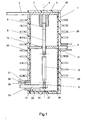
- FIGS. 1 and 3 to 6 illustrated five embodiments of the switch pole according to the invention each have a filled with an insulating gas, such as based on sulfur hexafluoride, nitrogen, oxygen or carbon dioxide or mixtures of these gases, such as air, with a pressure up to a few bar and largely tubular shaped insulating housing 1.
- an insulating gas such as based on sulfur hexafluoride, nitrogen, oxygen or carbon dioxide or mixtures of these gases, such as air
- the contact arrangement has two along an axis 4 relative to each other displaceable switching pieces 5, 6, of which the one, namely 5, is held stationary and is electrically conductively attached to a perpendicular to the axis 4 aligned and electrically connected to the power connector 2 metal plate 7 while the other switching piece, namely 6, is attached to a metal driven member 8 of a transmission 9 and can be moved by the gear 9 along the axis 4.
- the switching piece 5 need not necessarily be held stationary, it may also be arranged displaceably along the axis 4. Instead of a metal plate 7 may also be another current-conducting part, such as a cup or a carrying star, may be provided.
- the two contact pieces 5, 6 are shown only as arcing contacts.
- the contact arrangement also includes one of the leadership of continuous current serving, parallel to the arcing contacts switched Nennstromnapsan für aposimus für satusky satusky satusky satusky satusky satusky satusky satusky satusky satusky satusky satusky s, a heating volume, which serves in a switching operation of the blowing of a switching arc.
- the switching piece 6 is electrically connected to the power connector 3 via the output member 8, which serves as a contact piece carrier, an output member axially leading sliding contact arrangement 10, and a holder 11 designed as a metal carrier star or metal plate.
- the gearbox 9 has an insulating rod 12, which is held pivotably on the output member 8, and a shaft 13 which carries at its right-pointing end two unsigned crank arms, to which an end of the insulating rod 12 facing away from the output member 8 is pivotally mounted.
- the insulating housing 1 is constructed shell-shaped and has obviously an inner and an outer shell.
- the inner shell forms the wall of a contact arrangement receiving and filled with the insulating gas-tight container 20.
- the outer shell is designed as an insulator 30 and embeds the vessel 20 a.
- the vessel 20 is supported against a force caused by the pressure of the insulating gas to the outside. Therefore, it is sufficient that the vessel 20 before embedding in the insulator 30 has a dimensional stability which is sufficient to support its own weight and all parts held by it, for example the contact arrangement.
- the wall of the vessel 20 is formed predominantly of an electrically insulating material, such as in particular a polymeric or ceramic material, such as PTFE, which material is largely resistant to the action of the arc formed by the corrosive gases and good dielectric properties, such as high dielectric strength and good tracking resistance.
- This material may be monolithic or layered and also includes composites containing polymers filled with fibers and / or powders.
- the vessel generally comprises wall-made metal parts, which with the wall part formed of insulating material, for example by joining or gluing are connected in a gastight manner.
- the gas-tightness of the vessel 20 can by a on the Inside, in particular at the seams, applied elastically well deformable layer of the above-mentioned corrosion-resistant insulating material can be optimized.
- the vessel 20 contains a closable opening 21, which is arranged in a wall made of metal wall part of the vessel. This opening is used for the inlet or outlet of the insulating gas.
- sensors 22 are housed inside the vessel, which detect the state of the insulating gas, in particular its pressure, its temperature, its density, its insulating properties and / or its chemical composition and so during operation of the Wegerpols in a switchgear over a through the Vessel wall guided data line 23 transmitted information to a not shown control and monitoring device of the high voltage switch.
- the gear 9 is held in the vessel 20.
- the designed as a shaft 13 drive member of the transmission 9 is mounted in a designed as a metal disc 24 section of the vessel wall 20.
- the shaft 13 can be performed in a simple manner gas-tight through the vessel wall into the vessel interior.
- the opening 21 in the metal disk 24 is arranged. With an outside of the insulating housing 1 arranged valve 25, the opening 21 can be closed or kept open, so that as required insulating gas or other gas can be introduced into the interior of the vessel 20 or pumped out of the vessel again.
- a predetermined breaking point 27 is formed, which breaks above a still permissible internal pressure of the vessel 20, so that then escape the insulating gas via a molded-in insulator 30 outflow channel 31 to the outside can.
- the wall of the vessel 20 is in the embodiment according to Fig.1 from the apparent circular shaped metal plate 7, two formed as a hollow cylinder and made of insulating material housing portions 29, 29 ', also made of insulating material bottom 26 and the metal disc 24th educated.
- the transmission 9 in the hollow cylinder 29 ', gas-tight connection of the two hollow cylinders 29, 29' on the holder 11, attaching the contact piece 6 on the output member 8 of the transmission 9, attaching the contact piece 5 to the metal plate 7 and subsequent gas-tight insertion of the Switching piece 5 supporting metal plate 7 and the sensors 22 holding the bottom 26 so the vessel 20 can be made in a simple manner.
- the vessel 20 instead of the two hollow cylinders 29, 29 ', the bottom 26, the metal plate 7 and the holder 11 also consist of two along the axis 4 extending shells made of insulating material, each half the two end faces and the lateral surface of the comprise substantially hollow cylindrical vessel and in each of which half openings for receiving the current feedthroughs 2 and 3 and the metal disc 24 are formed.
- the transmission 9 and the sensors 22, the two half shells can be connected to each other, for example, by joining, welding and / or bonding to form the vessel 20.
- the vessel 20 is lined with an elastically easily deformable liner of an insulating material, which material, such as PTFE, is resistant to the arc generated by the arc-generating aggressive gases.
- the thus produced vessel 20 has a mechanical strength, which makes it possible as a self-contained unit in a Fig.2 to include apparent two-part mold 40.
- the mold 40 has two separable, pressure and / or vacuum-tight sealable half-shells 41, 42 and a non-designated passage opening for the metal disk 24.
- the interior of the vessel 20 can so via the vessel opening 21 and the valve 25 with an outside of the mold 40 located gas supply system 43 are connected.
- the mold 40 has two further openings, not shown. Air can escape from the mold through one of these openings, and liquid casting compound, typically filled or unfilled casting resin, in particular based on epoxy, can be passed through the mold into the mold 40.
- the two half-shells 41, 42 are closed and the shape of one of the two evacuated not shown openings. To relieve the vessel 20, this can be evacuated via the opening 21 at the same time.
- the mold is filled with potting compound under vacuum over the second of the two openings, not shown.
- potting compound can be pressed under pressure into the mold 40.
- the air may escape through the second opening in such an automatic pressure gelling process.
- Even with this casting method can be achieved by synchronous pressure control of the interior of the vessel 20 that the wall of the vessel 20 is kept free during the casting of undesirable forces. In contrast to casting under vacuum, the production times of the switch pole can be considerably shortened during automatic pressure gelling. If the mechanical strength of the vessel is sufficiently high, then the casting process can also be carried out if the insulating gas has already been introduced into the vessel 20 and the vessel is already closed.
- the vessel 20 After demolding the casting body, filling the vessel 20 with the gas supplied from the gas supply 43 insulating gas and closing the opening 21 of the switch pole is then completed.
- the outer surface of the insulator 30 may subsequently be provided with one or more layers of another insulating material so as to enable the properties of the insulator for particular applications. If the switch pole is to be used outdoors, it is advisable to provide a silicone coating.
- the insulator also encloses an air-filled space 32 accommodating the transmission 9, and the output member 8 of the transmission 9, which is displaceable along the axis 4 and serves as a carrier of the movable contact piece 6, is guided in a gastight manner through the wall of the vessel 20.
- the bottom of the vessel 20 is now formed by the bracket 11 formed as a metal plate.
- the filling opening 21 is formed, which can be easily opened or closed by means of arranged in the easily accessible space 32 valve 25 in the manufacture of the Wegerpols or during maintenance.
- One of two further openings in the metal plate 11 serves to receive the pressure relief valve 27 ', whereas arranged in the second opening of the sliding contact 10 and the driven member 8 is guided.
- the second opening is closed gas-tight by a arranged in the interior of the vessel 20, at the edge of the opening and on the lateral surface of the output member 8 held expansion body 14, such as a bellows made of corrosion-resistant material.
- the volume of the vessel 20 can be kept so small. This also applies to the embodiments of the Druckerpols after the Figures 5 and 6 ,
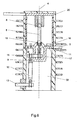
- the insulating housing 1 is held on a transmission 9 comprehensive support insulator 50, which is independent of the housing 1 produced and connected by means of a flange 51 to the housing 1. Also in this embodiment, it can be seen that along the axis 4 displaceable and serving as a carrier of the movable contact piece output member 8 of the transmission 9 gas-tight by the bottom of the vessel 20th serving metal plate 11 is guided.
- the support insulator 50 is not integrated into the insulator 30 but is manufactured and assembled independently of it, the mold used in embedding the vessel 20 in the insulator 30 can be kept small. This is of particular advantage when the insulator 30 is manufactured by automatic pressure gelation.
- the transmission 9 in addition to the shaft 13 and a shaft 15.
- the shaft 15 is guided gas-tight from the air-filled space 32 through the vessel wall into the interior of the vessel 20.
- the shaft 15 includes an outside and a disposed within the vessel 20, not shown for reasons of clarity crank arm.
- the arranged outside the vessel crank arm is rotatably connected to the shaft 13 facing away from the end of the insulating rod 12, whereas the housing 20 is arranged in the crank arm rotatably connected to one end of a coupling rod 16, the other end rotatable with the now completely inside the vessel 20 arranged driven member 8 is connected.
- the shaft 15 is rotatably mounted in the axially parallel wall of a molded as a recess in the current-carrying holder 11 metal cup 17.
- the current is passed through the now attached to (not designated) metal approaches the holder 11 sliding contact 10 and the bracket 11 to the power connector 3.
- a sliding feedthrough a generally easier gas-tight through the wall of the vessel 20 to be led, formed by the shaft 15 rotary feedthrough.
Landscapes
- Physics & Mathematics (AREA)
- Spectroscopy & Molecular Physics (AREA)
- Driving Mechanisms And Operating Circuits Of Arc-Extinguishing High-Tension Switches (AREA)
- Arc-Extinguishing Devices That Are Switches (AREA)
Priority Applications (4)
| Application Number | Priority Date | Filing Date | Title |
|---|---|---|---|
| EP07405012A EP1947669A1 (fr) | 2007-01-17 | 2007-01-17 | Pôle pour disjoncteur haute tension à isolation gazeuse et procédé de fabrication d'un tel pôle de disjoncteur |
| PCT/EP2008/050081 WO2008087060A1 (fr) | 2007-01-17 | 2008-01-07 | Pôle pour un interrupteur à haute tension isolé par gaz et procédé de fabrication d'un tel pôle d'interrupteur |
| EP08701261A EP2109870A1 (fr) | 2007-01-17 | 2008-01-07 | Pôle pour un interrupteur à haute tension isolé par gaz et procédé de fabrication d'un tel pôle d'interrupteur |
| CN2008800024600A CN101584013B (zh) | 2007-01-17 | 2008-01-07 | 用于气体绝缘的高压开关的开关极及其制造方法 |
Applications Claiming Priority (1)
| Application Number | Priority Date | Filing Date | Title |
|---|---|---|---|
| EP07405012A EP1947669A1 (fr) | 2007-01-17 | 2007-01-17 | Pôle pour disjoncteur haute tension à isolation gazeuse et procédé de fabrication d'un tel pôle de disjoncteur |
Publications (1)
| Publication Number | Publication Date |
|---|---|
| EP1947669A1 true EP1947669A1 (fr) | 2008-07-23 |
Family
ID=38024154
Family Applications (2)
| Application Number | Title | Priority Date | Filing Date |
|---|---|---|---|
| EP07405012A Withdrawn EP1947669A1 (fr) | 2007-01-17 | 2007-01-17 | Pôle pour disjoncteur haute tension à isolation gazeuse et procédé de fabrication d'un tel pôle de disjoncteur |
| EP08701261A Withdrawn EP2109870A1 (fr) | 2007-01-17 | 2008-01-07 | Pôle pour un interrupteur à haute tension isolé par gaz et procédé de fabrication d'un tel pôle d'interrupteur |
Family Applications After (1)
| Application Number | Title | Priority Date | Filing Date |
|---|---|---|---|
| EP08701261A Withdrawn EP2109870A1 (fr) | 2007-01-17 | 2008-01-07 | Pôle pour un interrupteur à haute tension isolé par gaz et procédé de fabrication d'un tel pôle d'interrupteur |
Country Status (3)
| Country | Link |
|---|---|
| EP (2) | EP1947669A1 (fr) |
| CN (1) | CN101584013B (fr) |
| WO (1) | WO2008087060A1 (fr) |
Cited By (6)
| Publication number | Priority date | Publication date | Assignee | Title |
|---|---|---|---|---|
| WO2010078888A1 (fr) * | 2008-12-19 | 2010-07-15 | Abb Technology Ag | Commutateur à isolation gazeuse |
| CN105864726A (zh) * | 2016-06-02 | 2016-08-17 | 湖南雁能森源电力设备有限公司 | 一种高压开关设备的照明装置 |
| WO2016177573A1 (fr) * | 2015-05-05 | 2016-11-10 | Siemens Aktiengesellschaft | Appareil de commutation électrique et installation de commutation correspondante |
| EP2932507A4 (fr) * | 2012-12-12 | 2016-12-14 | Southern States Llc | Commutateur de puissance électrique haute tension à fonctionnement magnétique à solénoïde scellé |
| CN107611894A (zh) * | 2017-10-25 | 2018-01-19 | 湖北省电力装备有限公司 | 一种大电流高压转换连接箱 |
| EP3416178A1 (fr) * | 2017-06-13 | 2018-12-19 | ABB Schweiz AG | Appareil électrique isolé par gaz doté de moyen pour empêcher une fuite de gaz |
Families Citing this family (4)
| Publication number | Priority date | Publication date | Assignee | Title |
|---|---|---|---|---|
| DE102012209307A1 (de) * | 2012-06-01 | 2013-12-05 | Siemens Aktiengesellschaft | Druckgasisolierte Elektroenergieübertragungseinrichtung |
| EP3179583A1 (fr) * | 2015-12-11 | 2017-06-14 | ABB Schweiz AG | Disjoncteur à vide de moyenne tension dans un boîtier isolé par sf6 pour une utilisation dans des environnements sous haute pression |
| DE102017221783A1 (de) * | 2017-12-04 | 2019-06-06 | Siemens Aktiengesellschaft | Anordnung und Verfahren zum Schalten hoher Spannungen mit einer Schalteinrichtung und genau einem Widerstandsstapel |
| JP6462973B1 (ja) * | 2018-05-24 | 2019-01-30 | 三菱電機株式会社 | ガス絶縁開閉装置 |
Citations (6)
| Publication number | Priority date | Publication date | Assignee | Title |
|---|---|---|---|---|
| CH357781A (de) * | 1958-05-30 | 1961-10-31 | Bbc Brown Boveri & Cie | Isolator für Schaltkammern |
| DE1243762B (de) * | 1966-03-18 | 1967-07-06 | Siemens Ag | Giessharzkoerper fuer elektrische Schalter |
| US3467760A (en) * | 1965-08-26 | 1969-09-16 | Bbc Brown Boveri & Cie | Electrical device with a fluid insulating medium |
| CH538186A (de) * | 1972-09-21 | 1973-06-15 | Sprecher & Schuh Ag | Verfahren zur Herstellung eines aus gegossenem, elektrisch isolierendem, härtbarem Kunststoff bestehenden Gehäuses für Hochspannungs-Leistungsschalter und nach dem Verfahren hergestelltes Gehäuse |
| EP0006392A1 (fr) * | 1978-06-12 | 1980-01-09 | Merlin Gerin | Enveloppe isolante en résine coulée pour appareillage électrique |
| EP0570020A2 (fr) * | 1990-03-01 | 1993-11-18 | S & C ELECTRIC COMPANY | Interrupteur pour la distribution électrique |
Family Cites Families (2)
| Publication number | Priority date | Publication date | Assignee | Title |
|---|---|---|---|---|
| DE3666521D1 (en) * | 1985-05-15 | 1989-11-23 | Alsthom | Switch with sulfur hexafluoride operating in a very low temperature environment |
| JP5127569B2 (ja) * | 2008-05-29 | 2013-01-23 | 株式会社東芝 | ガス絶縁開閉器 |
-
2007
- 2007-01-17 EP EP07405012A patent/EP1947669A1/fr not_active Withdrawn
-
2008
- 2008-01-07 EP EP08701261A patent/EP2109870A1/fr not_active Withdrawn
- 2008-01-07 WO PCT/EP2008/050081 patent/WO2008087060A1/fr not_active Ceased
- 2008-01-07 CN CN2008800024600A patent/CN101584013B/zh active Active
Patent Citations (6)
| Publication number | Priority date | Publication date | Assignee | Title |
|---|---|---|---|---|
| CH357781A (de) * | 1958-05-30 | 1961-10-31 | Bbc Brown Boveri & Cie | Isolator für Schaltkammern |
| US3467760A (en) * | 1965-08-26 | 1969-09-16 | Bbc Brown Boveri & Cie | Electrical device with a fluid insulating medium |
| DE1243762B (de) * | 1966-03-18 | 1967-07-06 | Siemens Ag | Giessharzkoerper fuer elektrische Schalter |
| CH538186A (de) * | 1972-09-21 | 1973-06-15 | Sprecher & Schuh Ag | Verfahren zur Herstellung eines aus gegossenem, elektrisch isolierendem, härtbarem Kunststoff bestehenden Gehäuses für Hochspannungs-Leistungsschalter und nach dem Verfahren hergestelltes Gehäuse |
| EP0006392A1 (fr) * | 1978-06-12 | 1980-01-09 | Merlin Gerin | Enveloppe isolante en résine coulée pour appareillage électrique |
| EP0570020A2 (fr) * | 1990-03-01 | 1993-11-18 | S & C ELECTRIC COMPANY | Interrupteur pour la distribution électrique |
Cited By (9)
| Publication number | Priority date | Publication date | Assignee | Title |
|---|---|---|---|---|
| WO2010078888A1 (fr) * | 2008-12-19 | 2010-07-15 | Abb Technology Ag | Commutateur à isolation gazeuse |
| CN102257688A (zh) * | 2008-12-19 | 2011-11-23 | Abb技术有限公司 | 气体绝缘开关 |
| CN102257688B (zh) * | 2008-12-19 | 2014-07-16 | Abb技术有限公司 | 气体绝缘开关 |
| EP2932507A4 (fr) * | 2012-12-12 | 2016-12-14 | Southern States Llc | Commutateur de puissance électrique haute tension à fonctionnement magnétique à solénoïde scellé |
| WO2016177573A1 (fr) * | 2015-05-05 | 2016-11-10 | Siemens Aktiengesellschaft | Appareil de commutation électrique et installation de commutation correspondante |
| CN105864726A (zh) * | 2016-06-02 | 2016-08-17 | 湖南雁能森源电力设备有限公司 | 一种高压开关设备的照明装置 |
| CN105864726B (zh) * | 2016-06-02 | 2019-04-02 | 湖南雁能森源电力设备有限公司 | 一种高压开关设备的照明装置 |
| EP3416178A1 (fr) * | 2017-06-13 | 2018-12-19 | ABB Schweiz AG | Appareil électrique isolé par gaz doté de moyen pour empêcher une fuite de gaz |
| CN107611894A (zh) * | 2017-10-25 | 2018-01-19 | 湖北省电力装备有限公司 | 一种大电流高压转换连接箱 |
Also Published As
| Publication number | Publication date |
|---|---|
| EP2109870A1 (fr) | 2009-10-21 |
| WO2008087060A8 (fr) | 2008-09-25 |
| WO2008087060A1 (fr) | 2008-07-24 |
| CN101584013A (zh) | 2009-11-18 |
| CN101584013B (zh) | 2012-11-14 |
Similar Documents
| Publication | Publication Date | Title |
|---|---|---|
| EP1947669A1 (fr) | Pôle pour disjoncteur haute tension à isolation gazeuse et procédé de fabrication d'un tel pôle de disjoncteur | |
| DE69620132T2 (de) | Hochspannungsschalter | |
| DE2354632C3 (de) | Vakuumleistungsschalter | |
| DE60013673T2 (de) | Schaltanlage und Leistungsschalteranordnung | |
| EP1617537B1 (fr) | Extrémité de câble | |
| DE102016002261A1 (de) | Anordnung und Verfahren zum Führen einer Schaltstange eines Hochspannungs-Leistungsschalters | |
| EP1569255A1 (fr) | Interrupteur de mise à la terre compact pour Disjoncteurs à isolation par gas | |
| DE69734440T2 (de) | Verbessertes abgedichtetes relais | |
| DE68915638T2 (de) | Schaltanlage. | |
| EP2319057B1 (fr) | Transformateur haute tension | |
| WO2004093276A2 (fr) | Interrupteur de mise a la terre pourvu d'un element de contact mobile | |
| DE102008000494A1 (de) | Gasdichte elektrische Durchführung durch eine Gehäusewand, insbesondere für einen gasgekühlten Generator | |
| WO2003017306A1 (fr) | Appareil de distribution electrique pour haute et moyenne tension | |
| DE4320906C2 (de) | Gehäuse für einen druckgasisolierten Hochspannungs- Leistungs-Schalter | |
| DE3436173A1 (de) | Schaltanlage | |
| DE10219299B3 (de) | Einpolig gekapselte und gasisolierte Schaltanlage | |
| DE102017222943A1 (de) | Anordnung und Verfahren zum Antreiben eines beweglichen Kontakts einer Vakuumschaltröhre in einem Hochspannungsleistungsschalter | |
| EP4562664A1 (fr) | Module de base pour dispositifs de commutation à haute tension avec interrupteurs à vide, et dispositif de commutation à haute tension comprenant le module de base | |
| DE2546490B2 (de) | Mehrpoliger Last- bzw. Leistungsschalter | |
| EP0703593B1 (fr) | Colonne polaire pour un disjoncteur électrique | |
| DE102006040036A1 (de) | Anordnung mit einem elektrischen Schaltgerät | |
| DE2744502A1 (de) | Mittelspannungsschalter | |
| DE102006056656A1 (de) | Schaltermodul für eine elektrische Schaltanlage | |
| DE29507391U1 (de) | An einem Tragmast montierbare mehrpolige Schalteinheit | |
| DE3718108A1 (de) | Vakuumschalter |
Legal Events
| Date | Code | Title | Description |
|---|---|---|---|
| PUAI | Public reference made under article 153(3) epc to a published international application that has entered the european phase |
Free format text: ORIGINAL CODE: 0009012 |
|
| AK | Designated contracting states |
Kind code of ref document: A1 Designated state(s): AT BE BG CH CY CZ DE DK EE ES FI FR GB GR HU IE IS IT LI LT LU LV MC NL PL PT RO SE SI SK TR |
|
| AX | Request for extension of the european patent |
Extension state: AL BA HR MK RS |
|
| AKX | Designation fees paid | ||
| REG | Reference to a national code |
Ref country code: DE Ref legal event code: 8566 |
|
| STAA | Information on the status of an ep patent application or granted ep patent |
Free format text: STATUS: THE APPLICATION IS DEEMED TO BE WITHDRAWN |
|
| 18D | Application deemed to be withdrawn |
Effective date: 20090124 |