EP1950010A2 - Robot et procédé de programmation d'un robot - Google Patents
Robot et procédé de programmation d'un robot Download PDFInfo
- Publication number
- EP1950010A2 EP1950010A2 EP07150146A EP07150146A EP1950010A2 EP 1950010 A2 EP1950010 A2 EP 1950010A2 EP 07150146 A EP07150146 A EP 07150146A EP 07150146 A EP07150146 A EP 07150146A EP 1950010 A2 EP1950010 A2 EP 1950010A2
- Authority
- EP
- European Patent Office
- Prior art keywords
- robot
- force
- forces
- point
- torque
- Prior art date
- Legal status (The legal status is an assumption and is not a legal conclusion. Google has not performed a legal analysis and makes no representation as to the accuracy of the status listed.)
- Granted
Links
Images





Classifications
-
- G—PHYSICS
- G05—CONTROLLING; REGULATING
- G05B—CONTROL OR REGULATING SYSTEMS IN GENERAL; FUNCTIONAL ELEMENTS OF SUCH SYSTEMS; MONITORING OR TESTING ARRANGEMENTS FOR SUCH SYSTEMS OR ELEMENTS
- G05B19/00—Program-control systems
- G05B19/02—Program-control systems electric
- G05B19/42—Recording and playback systems, i.e. in which the program is recorded from a cycle of operations, e.g. the cycle of operations being manually controlled, after which this record is played back on the same machine
- G05B19/423—Teaching successive positions by walk-through, i.e. the tool head or end effector being grasped and guided directly, with or without servo-assistance, to follow a path
-
- G—PHYSICS
- G05—CONTROLLING; REGULATING
- G05B—CONTROL OR REGULATING SYSTEMS IN GENERAL; FUNCTIONAL ELEMENTS OF SUCH SYSTEMS; MONITORING OR TESTING ARRANGEMENTS FOR SUCH SYSTEMS OR ELEMENTS
- G05B2219/00—Program-control systems
- G05B2219/30—Nc systems
- G05B2219/36—Nc in input of data, input key till input tape
- G05B2219/36432—By putting some constraints on some DOF, move within limited volumes, areas, planes, limits motion in x, y or z planes, virtual reality constraints
-
- G—PHYSICS
- G05—CONTROLLING; REGULATING
- G05B—CONTROL OR REGULATING SYSTEMS IN GENERAL; FUNCTIONAL ELEMENTS OF SUCH SYSTEMS; MONITORING OR TESTING ARRANGEMENTS FOR SUCH SYSTEMS OR ELEMENTS
- G05B2219/00—Program-control systems
- G05B2219/30—Nc systems
- G05B2219/36—Nc in input of data, input key till input tape
- G05B2219/36489—Position and force
-
- G—PHYSICS
- G05—CONTROLLING; REGULATING
- G05B—CONTROL OR REGULATING SYSTEMS IN GENERAL; FUNCTIONAL ELEMENTS OF SUCH SYSTEMS; MONITORING OR TESTING ARRANGEMENTS FOR SUCH SYSTEMS OR ELEMENTS
- G05B2219/00—Program-control systems
- G05B2219/30—Nc systems
- G05B2219/37—Measurements
- G05B2219/37319—Derive acceleration, force, torque from current
-
- G—PHYSICS
- G05—CONTROLLING; REGULATING
- G05B—CONTROL OR REGULATING SYSTEMS IN GENERAL; FUNCTIONAL ELEMENTS OF SUCH SYSTEMS; MONITORING OR TESTING ARRANGEMENTS FOR SUCH SYSTEMS OR ELEMENTS
- G05B2219/00—Program-control systems
- G05B2219/30—Nc systems
- G05B2219/39—Robotics, robotics to robotics hand
- G05B2219/39529—Force, torque sensor in wrist, end effector
Definitions
- the invention relates to a method for programming a robot and a robot.
- Robots are handling machines that are equipped for the automatic handling of objects with appropriate tools and programmable in several axes of motion, in particular with regard to orientation, position and workflow.
- Methods for programming the robot are understood as the planned procedure for generating user programs.
- a well-known programming method is the so-called teach-in programming, in which a movement information for the robot is created by approaching desired points in space with the help of a suitable device, such as a handheld programmer or a control panel, and acquisition of these space points in the robot controller.
- Another type of programming is the so-called play-back method, in which the programming of a work operation is performed by manually guiding the robot along a desired space curve.
- the axis positions or the TCP position (Tool Center Point Position) of the robot are transferred to the user program in a defined time or space frame.
- the EP 1 508 396 A1 discloses a method for controlling the pressing force of a robot guided welding tongs.
- the force acting on the welding gun is measured during welding and the robot is adjusted in this way, that the force acting on the welding gun force is equal to a predetermined desired force.
- the object of the invention is to provide a method for programming a robot, which allows an operator of the robot to program the robot in a relatively simple manner such that it has a predetermined force and / or torque behavior when executing the corresponding user program.
- Another object of the invention is to provide a corresponding robot.
- the robot is manually operated for programming the robot, in particular for programming a trajectory of a flange of the robot, so that the robot approaches at least one spatial point, ie exactly one spatial point or a plurality of spatial points.
- the manual approach of the at least one spatial point can be carried out in particular by a manual guidance of the robot or by means of a manually operable input device of the robot.
- the robot For manually guiding the robot, eg by pushing or pulling on robot axes or on one of the robot's flange attached force or torque sensor, the robot can work gravitationally compensated. Then sufficient for the manual guidance of the robot relatively small forces, which in turn causes a relatively simple guidance of the robot.
- the manually operable input device is, for example, a handheld terminal that may have traversing keys and other interaction elements (e.g., space mouse or joystick).
- Various operating modes can be set on the handheld terminal, which make it easier for a person moving the robot manually to move the robot in a targeted manner.
- the person may optionally manipulate the robot in a tool-based (TOOL) or workpiece centered (BASE) coordinate system.
- TOOL tool-based
- BASE workpiece centered
- the storage of the forces or torques can be achieved with an interaction element, e.g. a key, are initiated.
- the force applied by the robot or the torque applied by the robot is stored. It can be provided to set the force exerted or the torque exerted by manual guidance to desired target values, for example, by pressing the robot or its flange or the tool attached to the flange by the manual start against an object located at the corresponding point in space.
- the force at the TCP or the moments in the axes can only be determined if the drives brace the robot arm so that the desired forces or moments occur. These forces or moments can be made visible to the operator, for example via a display, but not felt by him or predetermined by leadership.
- the force or the torque is determined with a force or torque sensor attached to the flange.
- the setpoint forces and / or setpoint torques are set by the manual movement of the robot without contact with an object while simultaneously controlling the position or position of the robot.
- the robot does not form a closed kinematic chain with the environment, but keeps it open becomes, ie no object is touched.
- the robot is brought into the pose that is required for the desired task, eg polishing, by the operator.
- the robot can be positioned, for example, half a centimeter above the point / the track / the surface on which / at which a process is to be performed.
- the operator can now cause tension on the robot system by trying to move the robot by pushing and / or pulling on structural parts or on the flange of the robot, respectively the robot uses its internal axis and / or position control to maintain the current pose or position.
- Position control based on external sensor values is also conceivable.
- the pose / position control allows the operator to feel a virtual counterforce, comparable to the force he would feel if he pressed the tool against the part to be machined (ie, the robot is standing still). This enables him to teach the force or moments required for the process.
- the robot is position-controlled, it is also possible for it to move on a predefined trajectory. External forces can then be detected by an operator at each point.
- a variant of the method described above is suitable for recording the force / moment curve during manual guidance of the robot (i.e., the robot does not stand still). In doing so, the robot performs small test movements, which are barely noticeable by the operator, in order to find out in what degrees of freedom the robot can still move. Thus, the stiffness / compliance can be detected during the Vorcess a machining process.
- the robot can be provided with at least one force or torque sensor which measures the forces or torques.
- the force or torque sensor may in particular be attached to the flange of the robot. Then the signals emitted by the sensor can indicate the applied forces or torques in Cartesian coordinate values. If necessary, these values can also be converted into individual values.
- the robot has a plurality of axes, so that the applied forces or torques of the axes are stored for at least one point in space.
- the applied forces or torque in the axes can be determined, for example, with force or torque sensors mounted in the axes of the robot. If necessary, measured values generated by these sensors can then be converted into Cartesian values on the flange or at the so-called Tool Point Center of the robot.
- the forces or torques exerted by the robot can also be determined via the electrical currents of the electric motors.
- the electrical currents in particular give the forces or torques applied by the axes.
- the electrical currents are proportional to the applied forces or torques, depending on the type of motor used.
- the setpoints for forces and torques can also be entered manually.
- the stored force or the stored torque is an upper limit force to be exerted by the robot or an upper limit torque to be exerted by the robot.
- At least the position of an axis is additionally stored for at least one point in space.
- the positions of all axes can be stored.
- the robot is movable with respect to a plurality of degrees of freedom, and for the at least one space point for a first part of the degrees of freedom of the robot, the applied force or the applied torque and for a second one different from the first part of the degrees of freedom Part of the degrees of freedom stored the spatial coordinates of the spatial point, analogous to the axis positions and axis forces and torques.
- the location coordinates or the instantaneous position of the drive axes at the time of storage are stored, for example, in the program source text or in a data list assigned to the computer program.
- This position of the drive axes can be converted into a Cartesian position and orientation of the space point approached in space, expressed in the position of the so-called tool center point of the robot relative to a base coordinate system.
- This Cartesian position (including additional information about the resolution of usually several possible axis configurations, all of which give the same Cartesian position) can be stored instead of or in combination with the axis angles.
- this tool center point may be at the flange or other designated point of the robot, its tool (eg welding tip of a welding gun mounted on the robot flange) or space (welding tip of a welding gun mounted in the room).
- tool eg welding tip of a welding gun mounted on the robot flange
- space welding tip of a welding gun mounted in the room.
- robot controllers can use not only the axis positions but also the coordinate system that is currently used Tool, note the position and orientation (pose) of the Tool Center Point.
- the person programming a sequence of room points with the manual control unit, they can be reached on different lanes, depending on the robot control.
- PTP lanes point-to-point lanes
- all axes of the robot move in such a way that the desired pose is achieved on a straight line in the axle space.
- the Tool Center Point follows primarily a desired Cartesian course, e.g. on a straight line, circular or spline track in the room.
- a velocity profile e.g. time optimal or by specifying maximum speeds and accelerations.
- the robot according to the invention can be manually guided, for example, for the approach of at least one spatial point or can have a manual input device connected to the control device, by means of which the robot can be moved manually.
- the device for determining the force exerted by the robot or the torque exerted by the robot is, for example, at least one force or torque sensor, e.g. attached to the flange or in the axes of the robot.
- the device for determining the force exerted by the robot or the torque exerted by the robot can be configured such that it determines the force or the torque by means of measured electric currents of the electric motors.
- the stored force or torque may be an upper limit force to be applied by the robot or an upper limit torque to be applied by the robot.
- its control device is set up in such a way that it additionally stores the associated position of at least one axis for at least one spatial point.
- the control device can in particular be set up in such a way that it stores the positions of all axes.
- the robot according to the invention is movable with respect to a plurality of degrees of freedom, in particular with respect to six degrees of freedom, and the control device can be arranged according to an embodiment such that for the at least one space point for a first part of the degrees of freedom of the robot, the applied force or torque and for a second part of the degrees of freedom different from the first part of the degrees of freedom stores the spatial coordinates of the point in space. It is also possible that for the at least one space point for some degrees of freedom, the position and the applied force or the applied torque is stored.
- its control device is set up in such a way that it can move on the basis of a fixed path on which the robot is to move after approaching several spatial points, i. during program operation, forces to be exerted by the robot or torques during the movement along the path are calculated on the basis of the forces or torques determined for the spatial points.
- the forces and torques to be set by the robot according to the invention in the program mode can optionally be set manually in six Cartesian or all axis-specific degrees of freedom by a person in direct interaction with the robot according to the invention.
- the forces and moments to be set can also be set by offline programming.
- the forces or torques are stored in the control device of the robot according to the invention.
- the control device may be configured to provide for the transfer of the robot from one point / force torque profile to the next.
- a coordinate system already stored in the control device can be used, as is usual in a single storage of the coordinates of the spatial points.
- One of the axes of the coordinate system can in particular coincide with the axis of rotation.
- the coordinate system then also provides the direction of rotation.
- the applied force in the axial direction can be e.g. be saved with the convention that a positive force moves the axis in the positive direction.
- the torque about the axis may e.g. be stored with the convention that a positive torque causes rotation of the axis in a mathematically positive sense. If the robot comprises several axes, the torques of the individual axes can be denoted by ⁇ 1, ..., ⁇ n.
- a coordinate system When storing the torques or forces in Cartesian coordinates, a coordinate system can also be defined and the forces or torques are stored with the convention that a positive force in the direction of the Cartesian coordinate system or a positive torque about an axis of the Cartesian coordinate system a movement in the positive direction or a rotation in the positive direction causes about this axis.
- Possible names are: fx, fy, fz, nx, ny, nz.
- torques can be assigned to the axes as usual in physics. This avoids singularity problems in the orientation descriptions used in robotics.
- the structure for storing the forces or torques can be supplemented by elements that indicate when the desired forces or torques are considered to have been reached. Depending on the application, this may mean that the force or the moment is exceeded for the first time (in terms of amount), or that the force or the moment is present with an adjustable tolerance for a certain time.
- error corridors or ranges relating to the stored position and / or the stored forces or torques can be specified. This may be necessary, for example, if the robot can not necessarily reach a state of rest and, for example, attempts to apply a certain force at one point in space. As long as the robot has no equilibrium with respect to the sum of all forces and moments, the robot will move.
- the maximum error values to be specified can be used as a barrier to prevent the robot from leaving a specified area. This area can be related, for example, to the position and / or orientation of the tool center point in space, to forces or moments in the robot structure or to direction and size forces or moments acting externally on the Tool Center Point.
- One way to specify an error corridor or range, for example, for the forces or torques of a particular point in space is not to store the exact location coordinates of that point in space, but a geometric (three-dimensional) area, for example. in the form of a sphere in three-dimensional space to define the relevant point in space. This is done e.g. analogous in the orientation space, in the space of forces in the xyz direction or moments about xyz axes, with an error radius to be defined by the user. If the robot tries to reach this point in space with the desired force, outside the predetermined error range, then the robot can be automatically stopped.
- an action area can be defined within which the robot carries out its current operation.
- different states related to positions, orientations, forces or moments can be defined, the achievement of which ensures that the current operation is terminated and changed to the next program line and thus to the next action.
- the inventive method can be used particularly advantageous to realize haptic impressions.
- the forces or torques assigned to the spatial points can be ground. This blending can be done in a similar way to blurring determined spatial points to a trajectory.
- the individual spatial points e.g. according to a linear, circular, spline or point-to-point motion and by "blending" e.g. with polynomial curves to form a smooth contour.
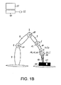
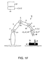
- FIGS. 1A-1F show several stages of a 6-axis articulated industrial robot R during programming, during which a certain force and / or torque characteristic is set for the industrial robot R, which should have this in an application.
- the in the Figures 1A-1F illustrated robot R has a plurality of axes 1-6, a plurality of levers 7-10 and a flange F on which a gripper 18 is attached.
- Each of the axes 1-6 is moved in the case of the present embodiment with an electric motor 11-16, wherein the motors 11-16 are electrically connected in a manner not shown to a control computer 17, so that the control computer 17 and one on the control computer 17th running computer program, the motors 11-16 can control such that the position and orientation of the flange F and thus of the robot R attached to the gripper 18 can be aligned substantially freely in space.
- the robot R is intended to fit a piston 19 in a gap 21 of a metal block 20.
- the position of the metal block is not identical in every process cycle, so that no position-based teach-in can take place.
- the metal block 20 may be used, for example, during later manufacturing steps for the manufacture of a cylinder.
- the robot R In order for the robot R in operation to be able to attach the piston 19, the robot R must have a control program which controls the robot R and runs on the control computer 17.
- This control program is created in the case of the present embodiment by means of teach-in programming.
- the robot R by means of a connected to the control computer 17 input device, such as a 6D mouse, a joystick or in the Figures 1A-1F illustrated handling device 22 such that the position and orientation of the gripper 18 with gripped piston 19 can be approached freely in space.
- the control computer 17 or a running on the control computer 17 computer program on the basis of inputs to the handling device 22, the electric motors 11-16 so controls, so that the axes 1-6 according to the desired position and orientation of the gripper 18th move.
- the robot R comprises a force sensor 23 attached to the flange F, which measures forces acting on the flange F or gripper 18.
- the force sensor 23 is connected in a manner not shown to the control computer 17 and transmits the measured forces associated signals to the control computer 17.
- the force sensor 23 measures forces in and across the longitudinal axis of the piston 19th
- the operator operating the manipulator 22 moves the gripper 18 toward the metal block 20 until the piston 19 contacts a surface 24 of the metal block 20, as shown in FIG Fig. 1B is shown.
- a force in the direction of movement of the robot R is measured with the force sensor 23 and the person by means of a Display device 25 connected to the control computer 17 is displayed.
- the person controls by means of the handling device 22 the robot R such that it moves the piston 19 with a substantially constant force in the direction of the gap 21, as in the Figures 1B and 1C is shown.
- Hits the piston 19 on the gap 21, Fig. 1C then changes the force acting on the piston 19 and thus on the robot R or torque, which in turn is detected with the dynamometer 23.
- the person may also recognize this condition by a yielding or a change in orientation of the piston 19.
- the person controls the robot R by means of the handling device 22 such that the piston 19 rises until it is aligned substantially perpendicular to the surface 24 of the metal block 24 and can be pressed into the gap 21.
- the person stores the forces acting on the robot R again by pressing the enter button of the handling device 22.
- the force corridor is in the case of the present embodiment, characterized in that act on the piston 19 as low as possible forces.
- This state is in turn stored with the control computer 17 by pressing the enter button of the manipulator 22.
- the robot R pushes the piston 19 into the gap 21 until the piston 19 reaches the lower boundary of the gap 21, as described in de Fig. 1E is illustrated. As a result, the piston 19 is joined in the metal block 20.
- the achievement of the lower limit of the gap 21 recognizes the person due to the distance traveled by the piston 19 when joining or by an increase in the force acting on the robot R force upon impact.
- the force required for joining in the final state is in turn stored in the control computer 17 by pressing the input key of the handling device 22.
- the gripper 18 is opened and removed from the piston 19, Fig. 1F , and the teach-in programming is finished.
- the computer program running on the control computer 17 controls the robot R in such a way that the robot R moves these pistons into their metal blocks in accordance with the force or torque determined during the teach-in programming just described. Characteristics moved.
- the corresponding positions of the robot R are stored, for example, the axis positions of the axes 1-6 are also stored for each state.
- error ranges or tolerance range with respect to the axis positions can be defined, as a result of which, in particular, compliant control methods can be used for the control of the robot R.
- the forces and possibly the Cartesian or axis-specific positions of the axes 1-6 are stored to discrete states.
- Fig. 2 illustrates a rounding of a force-torque curve stored during a teach-in programming.
- the Fig. 3 shows a corresponding flow chart.
- the forces or moments determined at individual points in time during the teach-in programming can be connected by smoothing with, for example, polynomial curves to form a smooth contour.
- a robot for example, in the Fig. 1 shown robot R, a component B with a fixed instead of the gripper 18 on the robot R tool edit.
- the robot R is to be controlled in such a way that the tool is in the Cartesian directions x, y of a system fixed in space, eg a world coordinate system with the coordinates x and y, on a curve K which is defined by points P0, P1a, P1b, P2a, P2b, P3a, P3b and P4 is moved.
- the movement begins at the point P0 at which the tool is to exert no force on the component B.
- the tool should not exert any force on the component B in the x-direction and in negative y direction to exert a constant force.
- Such a movement is suitable for example when deburring the component B with the tool.
- the tool should exert no force on the component B in the x-direction and the constant force in the negative y-direction.
- the robot R is to move the tool on a circle segment, wherein the tool is to exert on the component B, the constant force in the radial direction.
- the constant force acting in the radial direction should have components in the negative x and y direction.
- the tool should exert no force on the component B, the constant force in the negative x-direction and in the y-direction.
- no force should act on the component.
- the robot R or the tool moved with the robot R is moved up to the point P0 by means of the handling device 22, step S1 of FIG Fig. 3 shown flow chart. At point P0, no force acts on the tool. This is stored in the control computer 17, steps S2 and S3 of in the Fig. 2 shown flow chart.
- the robot R presses the tool onto a surface such that the tool exerts the constant force in the negative y-direction and no force in the x-direction.
- This information is stored in the control computer 17, steps S2 and S3 of in the Fig. 3 shown flow chart.
- the robot R is moved by means of the handling device 22 such that the tool reaches a point P2, step S1 of FIG Fig. 3 shown flow chart.
- the point P2 is located on a connecting line between the points P1, P1b and P2a and on a connecting line between the points P2b and P3a.
- the robot R presses the tool on a surface such that the tool also exerts the constant force in the negative y-direction and no force in the x-direction.
- This information is stored in the control computer 17, steps S2 and S3 of in the Fig. 3 shown flow chart.
- the robot R is moved by means of the handling device 22 such that the tool presses on a surface at point P2 such that the tool exerts the constant force in the negative x-direction and no force in the y-direction.
- This information is stored in the control computer 17, steps S2 and S3 of in the Fig. 3 shown flow chart.
- the robot R is moved by means of the handling device 22 in such a way that the tool reaches a point P3, step S1 of FIG Fig. 3 shown flow chart.
- the point P3 is located on the connecting line between the points P2b and P3a and on a horizontally aligned connecting line connecting the points P3 and P4.
- the robot R presses the tool onto a surface such that the tool exerts the constant force in the negative x-direction and no force in the y-direction.
- the robot R is moved by means of the handling device 22 such that the tool reaches the point P4, step S1 of the in the Fig. 3 shown flow chart.
- the tool exerts no force. This is stored in the control computer 17, steps S2 and S3 of in the Fig. 2 shown flow chart.
- the points P0, P1a, P1b, P2a, P2b, P3a, P3b and P4 Defines defined curve K, P1a, P1b, P2a, P2b, P3a, P3b thereby by blending, step S4 of in the Fig. 3 shown flow chart, and the target forces acting on the component B interpolated due to the stored forces to the points P0-P4 forces, step S5 of in the Fig. 3 shown flow chart.
- control computer 17 or a computer program running on the control computer 17 calculates that the tool exerts the constant force in the negative Y direction between the points P1b and P2a and the constant force in the negative x direction between the points P2b and P3a should. Due to the course of the curve K between the points P2a and P2b on a circular segment, the control computer 17 calculates the force profile acting on the component such that the tool exerts a constant force on the tool radially to the circle segment having negative force components in the x and y directions ,
- the computer program running on the control computer 17 calculates that the force acting on the component B should build up slowly until the force at the point P1b is constructed so that it is the constant force in the negative y-direction having.
- the computer program running on the control computer 17 calculates that the force acting on the component B slowly decreases until it reaches the value zero when the component B has arrived at the point P4.
- the axis positions of the axes 1-6 for the points P0, P1, P2, P3 and P4 can still be stored in the control computer 17.
- the computer program running on the control computer 17 calculates the axis positions of the axes 1-6 such that the tool has appropriate orientations and positions in space for the application of force.
- the smoothing algorithm gives the control the orientation of the tool for each point in time.
- the moments in the x, y, and z directions are smoothed according to the same algorithm used for the force or orientation components. These Moments are then applied in the desired coordinate system.
- the force profile is determined by the robot R presses the tool during teach-in programming against a surface.
- the force profile is programmed in the control computer 17 by means of the following teach-in programming:
- the robot R or the tool moved with the robot R is brought up to the point P0 by means of the manipulator 22 or by manually guiding the robot R, such as manual pulling or pushing on the robot R, without a surface or an object to touch, step S1 of the in the Fig. 3 shown flow chart.
- step S1 of the in the Fig. 3 shown flow chart At point P0, no force acts on the tool. This is stored in the control computer 17, steps S2 and S3 of in the Fig. 3 shown flow chart.
- the tool is brought up to the point P1 with the robot R and with the aid of the manipulator 22 or by manual guidance, without touching a surface or an object, step S1 of the flow chart.
- the desired pose of the robot R is set and then manually pulled or pushed on the robot R such that the tool or the robot R, the constant force in the negative y-direction and no Exerts force in the x-direction.
- This information is stored in the control computer 17, steps S2 and S3 of the flowchart.
- the robot R is moved by means of the manipulator 22 or by manually guiding the robot R so that the tool reaches the point P2 without touching an object or a surface, step S1 of the flowchart.
- the desired pose of the robot R is adjusted and manually pushed or pulled on the robot R, so that the tool or the robot R also exerts the constant force in the negative y-direction and no force in the x-direction.
- This information is stored in the control computer 17, steps S2 and S3 of the flowchart.
- the robot R is moved by means of the manipulator 22 or by manually guiding such that the tool reaches the point P3 without touching an object, step S1 of the flow chart.
- the point P3 is manually such zodes or pressed on the robot that the tool or the robot R exerts the constant force in the negative x-direction and no force in the y-direction.
- This information is stored in the control computer 17, steps S2 and S3 of the flowchart.
- the robot R is moved by means of the manipulator 22 or by manually guiding such that the tool reaches the point P4, step S1 of the flowchart.
- the points P0, P1a, P1b, P2a, P2b, P3a, P3b and P4 Defines defined curve K, P1a, P1b, P2a, P2b, P3a, P3b thereby by blending, step S4 of the flow chart, and the target forces acting on the component B interpolated or ground due to the stored forces to the points P0-P4 forces, Step S5 of the flowchart.
- FIGS. 4A-4C each show a fixed to the flange F of the robot R tool 41 with a tip 42 and a component 43 with a tool 41 facing surface 44th
- the robot R was set manually such that the tip 42 of the tool 41 has approached a predetermined space point with a certain force.
- the point in space is in the case of the present Embodiment described in Cartesian cord rivets and has the coordinates x 0 , y 0 and z 0 .
- the force applied by the robot R and the location coordinates of the approached space point were stored in the case of the present embodiment, but for the x-coordinate, a tolerance band was placed around the target coordinate x 0 .
- the robot R is to successively process a plurality of components 43 with the tool 41.
- the components 43 are each to be positioned so that they are aligned according to the predetermined spatial point. Due to tolerances, for example, due to different thicknesses of the components 43 or a relatively inaccurate positioning, it may be that the components 43 are not positioned exactly with respect to their x-coordinate. So show the FIGS. 4A and 4B the component 43 slightly offset to the right with respect to their desired position and the plane of the drawing. The Fig. 4C shows the component 43 exactly positioned.
- the tip 42 of the tool 41 would be the one in FIG Fig. 4A shown component 43 does not reach at all and the surface 44 of the in the Fig. 4B Although achieved component 43, but not exert the necessary force on the component 43. Only the exact positioned and in the Fig. 4C shown component 43 is achieved by the tip 42 of the tool 41 such that the tool exerts the required force on the component 43.
- This conventional operating mode corresponds to a conventional attitude control.
- the position to be approached with the tip 42 of the tool 41 is stored in the x-direction with the tolerance band around the x 0 coordinate in the control computer 17.
- the robot R moves the tool 41 in the direction of an arrow 45 until the robot R applies the force stored during the programming in the x-direction, since then the tip 42 of the tool 41 reaches the surface 44 with the stored force Has. Accordingly, the tip 42 reaches the surface 44 of the component 43 and exerts on this the stored force, even if the component 42 is positioned inaccurately.
- the tool 41 exerts the predetermined force on the component 43, which, as in the Fig. 5 shown, can easily deform.
- the robot moves under consideration of programmed limits until the desired force is reached.
- the movement may preferably take place in torque operation, stiffness regulation, impedance regulation or admittance regulation, alternatively in position control, until the contact with the component is detected, and then, for example, from in force control.
- the forces or moments are measured with the force sensor 23.
- the forces or moments acting or exerted on the robot R can also be determined by other means.
- One possibility is a derivation of the electric currents of the motors 11-16.
- the robot R can also be manually operated to the space points P0-P4 e.g. by pushing and pulling on the axles 1-6.
Landscapes
- Engineering & Computer Science (AREA)
- Robotics (AREA)
- Physics & Mathematics (AREA)
- General Physics & Mathematics (AREA)
- Automation & Control Theory (AREA)
- Manipulator (AREA)
- Numerical Control (AREA)
Applications Claiming Priority (1)
| Application Number | Priority Date | Filing Date | Title |
|---|---|---|---|
| DE102006061752A DE102006061752A1 (de) | 2006-12-28 | 2006-12-28 | Roboter und Verfahren zum Programmieren eines Roboters |
Publications (3)
| Publication Number | Publication Date |
|---|---|
| EP1950010A2 true EP1950010A2 (fr) | 2008-07-30 |
| EP1950010A3 EP1950010A3 (fr) | 2009-05-13 |
| EP1950010B1 EP1950010B1 (fr) | 2013-04-10 |
Family
ID=39465705
Family Applications (1)
| Application Number | Title | Priority Date | Filing Date |
|---|---|---|---|
| EP20070150146 Not-in-force EP1950010B1 (fr) | 2006-12-28 | 2007-12-19 | Robot et procédé de programmation d'un robot |
Country Status (2)
| Country | Link |
|---|---|
| EP (1) | EP1950010B1 (fr) |
| DE (1) | DE102006061752A1 (fr) |
Cited By (6)
| Publication number | Priority date | Publication date | Assignee | Title |
|---|---|---|---|---|
| EP2184659A1 (fr) * | 2008-10-10 | 2010-05-12 | Abb Ag | Procédé et dispositif d'apprentissage d'un robot industriel avec "lead-through" |
| WO2011082755A1 (fr) * | 2009-12-17 | 2011-07-14 | Kuka Laboratories Gmbh | Procédé et dispositif pour commander un manipulateur |
| US20160052128A1 (en) * | 2014-08-20 | 2016-02-25 | Kuka Roboter Gmbh | Method Of Programming An Industrial Robot And Industrial Robots |
| US10150214B2 (en) | 2015-03-31 | 2018-12-11 | Abb Schweiz Ag | Method for controlling an industrial robot by touch |
| DE102018210819A1 (de) * | 2018-07-02 | 2020-01-02 | Audi Ag | Verfahren zur Herstellung einer Fahrzeug-Traktionsbatterie |
| EP3807732A1 (fr) * | 2018-06-15 | 2021-04-21 | Universal Robots A/S | Entraînement libre à double mode de bras de robot |
Families Citing this family (19)
| Publication number | Priority date | Publication date | Assignee | Title |
|---|---|---|---|---|
| DE102008001664B4 (de) | 2008-05-08 | 2015-07-30 | Deutsches Zentrum für Luft- und Raumfahrt e.V. | Medizinischer Roboter und Verfahren zur Erfüllung der Performanceanforderung eines medizinischen Roboters |
| DE102008043262A1 (de) * | 2008-10-29 | 2010-05-06 | Ifm Electronic Gmbh | Bedienelement zur Einstellung eines Messwertaufnehmers für die Automatisierungstechnik |
| DE102009034938B4 (de) * | 2009-07-28 | 2015-10-15 | Sensodrive Gmbh | Verfahren zur Kommandierung eines Bewegungssystems mit einer Messeinrichtung |
| EP2453325A1 (fr) * | 2010-11-16 | 2012-05-16 | Universal Robots ApS | Procédé et support de commande d'un robot |
| JP6182143B2 (ja) | 2011-09-28 | 2017-08-16 | ユニバーサル ロボッツ アクツイエセルスカプ | ロボットの較正およびプログラミング |
| DE102012012316B4 (de) * | 2012-06-20 | 2015-05-07 | Fanuc Corporation | Robotersteuerung, die eine Kraftsteuerung unter Verwendung eines dreiaxialen Kraftsensors durchführt |
| JP7042554B2 (ja) | 2014-03-04 | 2022-03-28 | ユニバーサル ロボッツ アクツイエセルスカプ | 安全機能を有する工業用ロボットとその安全制御のための方法 |
| US9403273B2 (en) * | 2014-05-23 | 2016-08-02 | GM Global Technology Operations LLC | Rapid robotic imitation learning of force-torque tasks |
| JP6678648B2 (ja) | 2014-09-26 | 2020-04-08 | テラダイン、 インコーポレイテッド | グリッパと自動試験装置 |
| KR102603939B1 (ko) | 2015-07-08 | 2023-11-20 | 유니버셜 로보츠 에이/에스 | 제3자 기여를 가진 산업용 로봇의 최종 사용자 프로그래밍 확장 방법 |
| TWI805545B (zh) | 2016-04-12 | 2023-06-21 | 丹麥商環球機器人公司 | 用於藉由示範來程式化機器人之方法和電腦程式產品 |
| DE102016123909A1 (de) * | 2016-12-09 | 2018-06-14 | Abb Schweiz Ag | Verfahren zur Minimierung von Belastungen der Gelenkverbindungen eines Manipulators |
| DE102017118985B4 (de) | 2017-04-23 | 2019-10-02 | Franka Emika Gmbh | Schraubvorrichtung |
| DE102017005581B4 (de) * | 2017-06-13 | 2019-02-21 | Kuka Deutschland Gmbh | Steuern eines Roboters |
| EP4049104B1 (fr) | 2019-10-22 | 2026-02-18 | Universal Robots A/S | Bras de robot ayant une limite tridimensionnelle adaptative dans un actionnement libre |
| DK180508B1 (en) | 2019-10-22 | 2021-06-03 | Universal Robots As | Maintaining free-drive mode of robot arm for period of time |
| WO2021078344A1 (fr) | 2019-10-22 | 2021-04-29 | Universal Robots A/S | Activation sécurisée du mode à entraînement libre d'un bras de robot |
| USD1099187S1 (en) | 2022-01-14 | 2025-10-21 | Universal Robots A/S | Robot joint |
| USD1082878S1 (en) | 2022-01-14 | 2025-07-08 | Universal Robots A/S | Robot joint |
Citations (1)
| Publication number | Priority date | Publication date | Assignee | Title |
|---|---|---|---|---|
| EP1508396A1 (fr) | 2003-08-20 | 2005-02-23 | KUKA Roboter GmbH | Méthode et dispositif pour le contrôle de la force de pression d'une pince de soudage |
Family Cites Families (11)
| Publication number | Priority date | Publication date | Assignee | Title |
|---|---|---|---|---|
| DE69116901T2 (de) * | 1990-02-27 | 1996-07-18 | Toshiba Kawasaki Kk | Robotersteuerung |
| EP0573657B1 (fr) * | 1991-11-26 | 1997-08-27 | Hitachi Construction Machinery Co., Ltd. | Controleur de robot |
| JPH05303422A (ja) * | 1992-04-27 | 1993-11-16 | Nippon Telegr & Teleph Corp <Ntt> | 直接教示方式ロボット |
| SE508216C2 (sv) * | 1993-03-12 | 1998-09-14 | Abb Stal Ab | Automatisk efterbearbetning av skovlar till roterande maskiner |
| JPH06278007A (ja) * | 1993-03-31 | 1994-10-04 | Tokico Ltd | 研削ロボット |
| JPH07132435A (ja) * | 1993-11-08 | 1995-05-23 | Nippon Telegr & Teleph Corp <Ntt> | ロボット作業算出教示方法 |
| US5495410A (en) * | 1994-08-12 | 1996-02-27 | Minnesota Mining And Manufacturing Company | Lead-through robot programming system |
| US6285920B1 (en) * | 2000-02-18 | 2001-09-04 | Fanuc Robotics North America | Method of robot teaching with motion constraints |
| US6385508B1 (en) * | 2000-10-31 | 2002-05-07 | Fanuc Robotics North America, Inc. | Lead-through teach handle assembly and method of teaching a robot assembly |
| JP3961408B2 (ja) * | 2002-11-21 | 2007-08-22 | ファナック株式会社 | 組立て方法及び装置 |
| DE102004020099A1 (de) * | 2004-04-24 | 2005-11-17 | Kuka Roboter Gmbh | Verfahren und Vorrichtung zum Beeinflussen eines mehrachsigen Handhabungsgeräts |
-
2006
- 2006-12-28 DE DE102006061752A patent/DE102006061752A1/de not_active Ceased
-
2007
- 2007-12-19 EP EP20070150146 patent/EP1950010B1/fr not_active Not-in-force
Patent Citations (1)
| Publication number | Priority date | Publication date | Assignee | Title |
|---|---|---|---|---|
| EP1508396A1 (fr) | 2003-08-20 | 2005-02-23 | KUKA Roboter GmbH | Méthode et dispositif pour le contrôle de la force de pression d'une pince de soudage |
Non-Patent Citations (1)
| Title |
|---|
| "An Exploratory Haptic Based Robotic Path Planning And Training Tool", PROCEEDINGS OF THE 2002 IEEE INTERNATIONAL CONFERENCE ON ROBOTIC & AUTOMATION, WASHINGTON DC, May 2002 (2002-05-01), pages 438 - 443 |
Cited By (16)
| Publication number | Priority date | Publication date | Assignee | Title |
|---|---|---|---|---|
| EP2184659A1 (fr) * | 2008-10-10 | 2010-05-12 | Abb Ag | Procédé et dispositif d'apprentissage d'un robot industriel avec "lead-through" |
| US10076841B2 (en) | 2009-12-17 | 2018-09-18 | Kuka Deutschland Gmbh | Method and device for controlling a manipulator |
| WO2011082755A1 (fr) * | 2009-12-17 | 2011-07-14 | Kuka Laboratories Gmbh | Procédé et dispositif pour commander un manipulateur |
| CN102741022A (zh) * | 2009-12-17 | 2012-10-17 | 库卡实验室有限公司 | 用于控制机械手的方法和装置 |
| CN102741022B (zh) * | 2009-12-17 | 2015-09-30 | 库卡机器人有限公司 | 用于控制机械手的方法和装置 |
| EP2883665A3 (fr) * | 2009-12-17 | 2015-10-14 | KUKA Laboratories GmbH | Procédé et dispositif destinés à la commande d'un manipulateur |
| US9227321B2 (en) | 2009-12-17 | 2016-01-05 | Kuka Roboter Gmbh | Method and device for controlling a manipulator |
| CN105291102A (zh) * | 2009-12-17 | 2016-02-03 | 库卡机器人有限公司 | 用于控制机械手的方法和装置 |
| CN105291102B (zh) * | 2009-12-17 | 2018-12-07 | 库卡机器人有限公司 | 用于控制机械手的方法和装置 |
| CN105388879A (zh) * | 2014-08-20 | 2016-03-09 | 库卡罗伯特有限公司 | 用于对工业机器人编程的方法和对应的工业机器人 |
| US9579787B2 (en) * | 2014-08-20 | 2017-02-28 | Kuka Roboter Gmbh | Method of programming an industrial robot and industrial robots |
| US20160052128A1 (en) * | 2014-08-20 | 2016-02-25 | Kuka Roboter Gmbh | Method Of Programming An Industrial Robot And Industrial Robots |
| US10150214B2 (en) | 2015-03-31 | 2018-12-11 | Abb Schweiz Ag | Method for controlling an industrial robot by touch |
| EP3807732A1 (fr) * | 2018-06-15 | 2021-04-21 | Universal Robots A/S | Entraînement libre à double mode de bras de robot |
| EP3807732B1 (fr) * | 2018-06-15 | 2025-12-24 | Universal Robots A/S | Entraînement libre à double mode de bras de robot |
| DE102018210819A1 (de) * | 2018-07-02 | 2020-01-02 | Audi Ag | Verfahren zur Herstellung einer Fahrzeug-Traktionsbatterie |
Also Published As
| Publication number | Publication date |
|---|---|
| DE102006061752A1 (de) | 2008-07-03 |
| EP1950010A3 (fr) | 2009-05-13 |
| EP1950010B1 (fr) | 2013-04-10 |
Similar Documents
| Publication | Publication Date | Title |
|---|---|---|
| EP1950010B1 (fr) | Robot et procédé de programmation d'un robot | |
| EP2868445B1 (fr) | Procédé de programmation de déroulements de mouvement d'un robot industriel redondant et robot industriel associé | |
| EP2851162B1 (fr) | Procédé de réglage manuel de la pose d'un bras manipulateur d'un robot industriel et robot industriel associé | |
| EP2212753B1 (fr) | Procédé pour permettre à un manipulateur de parcourir une trajectoire donnée, ainsi que dispositif de commande pour la mise en oeuvre d' un tel procédé | |
| DE102018116053B4 (de) | Robotersystem und Roboterlernverfahren | |
| DE102014216514B3 (de) | Verfahren zum Programmieren eines Industrieroboters und zugehöriger Industrieroboter | |
| DE102008062622B9 (de) | Verfahren und Vorrichtung zur Befehlseingabe in eine Steuerung eines Manipulators | |
| EP2000872B1 (fr) | Robot industriel et procédé de programmation d'un robot industriel | |
| DE69925204T2 (de) | Robotersteuerung | |
| EP2905111B1 (fr) | Procédé de programmation d'un robot industriel et robot industriel correspondant | |
| DE102011079117B4 (de) | Verfahren zum Programmieren eines Roboters | |
| EP2223191B1 (fr) | Robot industriel et procédé de programmation d'un robot industriel | |
| DE102008041602B4 (de) | Roboter und Verfahren zum Steuern eines Roboters | |
| EP2303521B1 (fr) | Robot industriel et procédé de planification de trajectoire pour commander le déplacement d un robot industriel | |
| DE102018007842B4 (de) | Steuergerät zum Überwachen der Bewegungsrichtung eines Betätigungswerkzeugs | |
| DE102015114013B4 (de) | Verfahren und Vorrichtung zur Steuerung des Betriebs eines Roboters | |
| EP2392435A2 (fr) | Système de manipulation d'outil et procédé de manipulation de pièces usinées à l'aide de manipulateurs coopérants | |
| WO2016193217A1 (fr) | Procédé pour faire fonctionner un robot, robot associé équipé d'un dispositif de vibration et poste de travail robotisé | |
| WO2018010842A1 (fr) | Résolution redondante pour manipulateur redondant | |
| DE102009007181A1 (de) | Verfahren zum Abfahren einer vorgegebenen Bahn durch einen Manipulator, sowie Steuervorrichtung zur Durchführung eines solchen Verfahrens | |
| EP3569367A1 (fr) | Détermination d'un mouvement d'un dispositif assistée par ordinateur | |
| EP3448631A1 (fr) | Robot à support mobile et manipulateur | |
| DE102006036490A1 (de) | Verfahren und Vorrichtung zum Steuern eines Handhabungsgeräts | |
| DE202020000371U1 (de) | Lineares Kupplungselement |
Legal Events
| Date | Code | Title | Description |
|---|---|---|---|
| PUAI | Public reference made under article 153(3) epc to a published international application that has entered the european phase |
Free format text: ORIGINAL CODE: 0009012 |
|
| AK | Designated contracting states |
Kind code of ref document: A2 Designated state(s): AT BE BG CH CY CZ DE DK EE ES FI FR GB GR HU IE IS IT LI LT LU LV MC MT NL PL PT RO SE SI SK TR |
|
| AX | Request for extension of the european patent |
Extension state: AL BA HR MK RS |
|
| RIC1 | Information provided on ipc code assigned before grant |
Ipc: G05B 19/423 20060101AFI20080812BHEP Ipc: B25J 9/22 20060101ALI20080812BHEP |
|
| PUAL | Search report despatched |
Free format text: ORIGINAL CODE: 0009013 |
|
| RIC1 | Information provided on ipc code assigned before grant |
Ipc: B25J 9/22 20060101ALI20090331BHEP Ipc: G05B 19/423 20060101AFI20080812BHEP Ipc: B25J 9/16 20060101ALI20090331BHEP |
|
| AK | Designated contracting states |
Kind code of ref document: A3 Designated state(s): AT BE BG CH CY CZ DE DK EE ES FI FR GB GR HU IE IS IT LI LT LU LV MC MT NL PL PT RO SE SI SK TR |
|
| AX | Request for extension of the european patent |
Extension state: AL BA HR MK RS |
|
| 17P | Request for examination filed |
Effective date: 20091019 |
|
| AKX | Designation fees paid |
Designated state(s): DE FR IT SE |
|
| 17Q | First examination report despatched |
Effective date: 20100326 |
|
| RAP1 | Party data changed (applicant data changed or rights of an application transferred) |
Owner name: KUKA LABORATORIES GMBH |
|
| GRAP | Despatch of communication of intention to grant a patent |
Free format text: ORIGINAL CODE: EPIDOSNIGR1 |
|
| GRAP | Despatch of communication of intention to grant a patent |
Free format text: ORIGINAL CODE: EPIDOSNIGR1 |
|
| GRAS | Grant fee paid |
Free format text: ORIGINAL CODE: EPIDOSNIGR3 |
|
| GRAA | (expected) grant |
Free format text: ORIGINAL CODE: 0009210 |
|
| AK | Designated contracting states |
Kind code of ref document: B1 Designated state(s): DE FR IT SE |
|
| REG | Reference to a national code |
Ref country code: DE Ref legal event code: R096 Ref document number: 502007011590 Country of ref document: DE Effective date: 20130606 |
|
| PG25 | Lapsed in a contracting state [announced via postgrant information from national office to epo] |
Ref country code: SE Free format text: LAPSE BECAUSE OF FAILURE TO SUBMIT A TRANSLATION OF THE DESCRIPTION OR TO PAY THE FEE WITHIN THE PRESCRIBED TIME-LIMIT Effective date: 20130410 |
|
| PLBE | No opposition filed within time limit |
Free format text: ORIGINAL CODE: 0009261 |
|
| STAA | Information on the status of an ep patent application or granted ep patent |
Free format text: STATUS: NO OPPOSITION FILED WITHIN TIME LIMIT |
|
| 26N | No opposition filed |
Effective date: 20140113 |
|
| REG | Reference to a national code |
Ref country code: DE Ref legal event code: R097 Ref document number: 502007011590 Country of ref document: DE Effective date: 20140113 |
|
| REG | Reference to a national code |
Ref country code: DE Ref legal event code: R082 Ref document number: 502007011590 Country of ref document: DE Representative=s name: EGE LEE & PARTNER PATENTANWAELTE PARTGMBB, DE Ref country code: DE Ref legal event code: R082 Ref document number: 502007011590 Country of ref document: DE Representative=s name: FUNK & BOESS GBR, DE Ref country code: DE Ref legal event code: R081 Ref document number: 502007011590 Country of ref document: DE Owner name: KUKA ROBOTER GMBH, DE Free format text: FORMER OWNER: KUKA LABORATORIES GMBH, 86165 AUGSBURG, DE |
|
| REG | Reference to a national code |
Ref country code: FR Ref legal event code: PLFP Year of fee payment: 9 |
|
| REG | Reference to a national code |
Ref country code: FR Ref legal event code: PLFP Year of fee payment: 10 |
|
| REG | Reference to a national code |
Ref country code: DE Ref legal event code: R082 Ref document number: 502007011590 Country of ref document: DE Representative=s name: EGE LEE & PARTNER PATENTANWAELTE PARTGMBB, DE Ref country code: DE Ref legal event code: R082 Ref document number: 502007011590 Country of ref document: DE Representative=s name: BOESS, DIETER ALEXANDER, DIPL.-ING. (UNIV.), DE |
|
| REG | Reference to a national code |
Ref country code: FR Ref legal event code: PLFP Year of fee payment: 11 |
|
| REG | Reference to a national code |
Ref country code: DE Ref legal event code: R082 Ref document number: 502007011590 Country of ref document: DE Representative=s name: BOESS, DIETER ALEXANDER, DIPL.-ING. (UNIV.), DE Ref country code: DE Ref legal event code: R082 Ref document number: 502007011590 Country of ref document: DE Representative=s name: EGE LEE & PARTNER PATENTANWAELTE PARTGMBB, DE Ref country code: DE Ref legal event code: R081 Ref document number: 502007011590 Country of ref document: DE Owner name: KUKA DEUTSCHLAND GMBH, DE Free format text: FORMER OWNER: KUKA ROBOTER GMBH, 86165 AUGSBURG, DE |
|
| REG | Reference to a national code |
Ref country code: DE Ref legal event code: R082 Ref document number: 502007011590 Country of ref document: DE Representative=s name: BOESS, DIETER ALEXANDER, DIPL.-ING. (UNIV.), DE |
|
| PGFP | Annual fee paid to national office [announced via postgrant information from national office to epo] |
Ref country code: DE Payment date: 20191203 Year of fee payment: 13 |
|
| PGFP | Annual fee paid to national office [announced via postgrant information from national office to epo] |
Ref country code: IT Payment date: 20191209 Year of fee payment: 13 Ref country code: FR Payment date: 20191115 Year of fee payment: 13 |
|
| REG | Reference to a national code |
Ref country code: DE Ref legal event code: R119 Ref document number: 502007011590 Country of ref document: DE |
|
| PG25 | Lapsed in a contracting state [announced via postgrant information from national office to epo] |
Ref country code: FR Free format text: LAPSE BECAUSE OF NON-PAYMENT OF DUE FEES Effective date: 20201231 Ref country code: IT Free format text: LAPSE BECAUSE OF NON-PAYMENT OF DUE FEES Effective date: 20201219 |
|
| PG25 | Lapsed in a contracting state [announced via postgrant information from national office to epo] |
Ref country code: DE Free format text: LAPSE BECAUSE OF NON-PAYMENT OF DUE FEES Effective date: 20210701 |