EP1950044A2 - Aufzeichnungsvorrichtung mit Aufnahmekopf und Aufzeichnungsverfahren unter Verwendung des Aufnahmekopfs - Google Patents
Aufzeichnungsvorrichtung mit Aufnahmekopf und Aufzeichnungsverfahren unter Verwendung des Aufnahmekopfs Download PDFInfo
- Publication number
- EP1950044A2 EP1950044A2 EP08001126A EP08001126A EP1950044A2 EP 1950044 A2 EP1950044 A2 EP 1950044A2 EP 08001126 A EP08001126 A EP 08001126A EP 08001126 A EP08001126 A EP 08001126A EP 1950044 A2 EP1950044 A2 EP 1950044A2
- Authority
- EP
- European Patent Office
- Prior art keywords
- recording medium
- thermosensitive recording
- laser
- record head
- Prior art date
- Legal status (The legal status is an assumption and is not a legal conclusion. Google has not performed a legal analysis and makes no representation as to the accuracy of the status listed.)
- Withdrawn
Links
Images





Classifications
-
- B—PERFORMING OPERATIONS; TRANSPORTING
- B41—PRINTING; LINING MACHINES; TYPEWRITERS; STAMPS
- B41J—TYPEWRITERS; SELECTIVE PRINTING MECHANISMS, i.e. MECHANISMS PRINTING OTHERWISE THAN FROM A FORME; CORRECTION OF TYPOGRAPHICAL ERRORS
- B41J2/00—Typewriters or selective printing mechanisms characterised by the printing or marking process for which they are designed
- B41J2/435—Typewriters or selective printing mechanisms characterised by the printing or marking process for which they are designed characterised by selective application of radiation to a printing material or impression-transfer material
- B41J2/475—Typewriters or selective printing mechanisms characterised by the printing or marking process for which they are designed characterised by selective application of radiation to a printing material or impression-transfer material for heating selectively by radiation or ultrasonic waves
- B41J2/4753—Typewriters or selective printing mechanisms characterised by the printing or marking process for which they are designed characterised by selective application of radiation to a printing material or impression-transfer material for heating selectively by radiation or ultrasonic waves using thermosensitive substrates, e.g. paper
-
- B—PERFORMING OPERATIONS; TRANSPORTING
- B41—PRINTING; LINING MACHINES; TYPEWRITERS; STAMPS
- B41J—TYPEWRITERS; SELECTIVE PRINTING MECHANISMS, i.e. MECHANISMS PRINTING OTHERWISE THAN FROM A FORME; CORRECTION OF TYPOGRAPHICAL ERRORS
- B41J2/00—Typewriters or selective printing mechanisms characterised by the printing or marking process for which they are designed
- B41J2/435—Typewriters or selective printing mechanisms characterised by the printing or marking process for which they are designed characterised by selective application of radiation to a printing material or impression-transfer material
- B41J2/47—Typewriters or selective printing mechanisms characterised by the printing or marking process for which they are designed characterised by selective application of radiation to a printing material or impression-transfer material using the combination of scanning and modulation of light
- B41J2/471—Typewriters or selective printing mechanisms characterised by the printing or marking process for which they are designed characterised by selective application of radiation to a printing material or impression-transfer material using the combination of scanning and modulation of light using dot sequential main scanning by means of a light deflector, e.g. a rotating polygonal mirror
- B41J2/473—Typewriters or selective printing mechanisms characterised by the printing or marking process for which they are designed characterised by selective application of radiation to a printing material or impression-transfer material using the combination of scanning and modulation of light using dot sequential main scanning by means of a light deflector, e.g. a rotating polygonal mirror using multiple light beams, wavelengths or colours
Definitions
- This invention relates to a recording apparatus with a record head which is composed of a plurality of recording elements arranged in a line and which records two-dimensional image or other information on a recording medium, and to a recording method using the record head.
- An array head is a record head composed of a plurality of recording elements arranged in a line. Recording methods using an array head are, for example, of the following two types.
- a first method is to arrange in parallel with the main scanning direction an array head which has the same length as that of the main scanning range like a thermal head, transport a recording medium, such as recording paper, in the vertical scanning direction perpendicular to the main scanning direction with respect to the array head, thereby recording two-dimensional or other information on the recording medium.
- Jpn. Pat. Appln. KOKAI Publication No. 2001-341429 has disclosed an initializing method and a rewriting method of obtaining good recorded images without residual images (uneven development) in rewriting the images on a reversible thermosensitive recording medium, and an apparatus for the methods. Jpn. Pat. Appln. KOKAI Publication No.
- 2001-341429 has described the operation of causing the thermal head to heat to the color developing temperature the entire surface or recording area of the reversible thermosensitive recording medium to be colored or decolored according to the difference in heating temperature or cooling speed after heating to color the entire surface or recording area, thereby uniformizing the recording layer.
- a second method is to provide an array head composed of a plurality of recording elements arranged in a line in parallel with a direction in which a recording medium, such as a recording sheet, is transported, stop transporting the recording medium temporarily and cause the array head to scan in the main scanning direction perpendicular to the transporting direction of the recording medium to record a plurality of lines of image or other information on the recording medium at the same time, and then transport the recording medium over a distance corresponding to a plurality of lines and record a plurality of lines of image or other information on the recording medium repeatedly, thereby recording two-dimensional image or other information on the recording medium.
- a third method is used in, for example, a laser printer.
- the third method is to apply to a polygon mirror 2 the laser beam output from a single laser light source 1, such as a semiconductor laser, as shown in FIG. 18 , to cause the laser beam to scan in the main scanning direction A by the rotation or reciprocating movement of the polygon mirror 2 and at the same time, and transport, for example, a rewritable thermosensitive recording medium 3 capable of thermosensitive recording in the vertical scanning direction B, thereby recording two-dimensional image or other information on the thermosensitive recording medium 3.
- a fourth method uses a semiconductor laser array 4 composed of a plurality of laser light sources arranged in a line as shown in FIG. 19 .
- the fourth method is to cause the semiconductor laser array 4 to scan in the main scanning direction and at the same time, transport a thermosensitive recording medium 3 in the vertical scanning direction, thereby recording two-dimensional image or other information on the thermosensitive recording medium 3.
- the thermosensitive recording medium 3 is a rewritable reversible medium which alternates between coloring and decoloring by specific temperature heating control and enables thermosensitive recording and thermosensitive erasing.
- FIG. 20 shows a coloring and erasing characteristic of the thermosensitive recording medium 3.
- the thermosensitive recording medium 3 When being heated to, for example, a melting point of 180°C or higher, the thermosensitive recording medium 3 goes into a state where the dyes in the print layer and a developer are mixed with one another. Rapid cooling from this state causes the dyes and developer to be crystallized while they are mixed with one another, thereby producing colors.
- the thermosensitive recording medium 3 is cooled slowly, the dyes and developer crystallize separately.
- thermosensitive recording medium 3 cannot keep the colored state and goes into the erased state. Moreover, even at a temperature equal to or lower than the melting point of the dyes and developer, if the thermosensitive recording medium 3 is heated at this temperature for a specific period of time, the dyes and developer are separated from one another and crystallize, with the result that the thermosensitive recording medium 3 goes into the erased state.
- the erase temperature at this time is in the range of about 130°C to 170°C. As described above, with the thermosensitive recording medium 3, information is printed and erased by controlling the temperature and time exactly.
- thermosensitive recording paper since the thermal head is brought into contact with the thermosensitive recording paper, the protective layer of the thermosensitive recording paper might be damaged.
- the transportation of the recording medium has to be stopped temporarily each time a plurality of lines of image or other information are recorded simultaneously onto the recording medium. Therefore, the second method is not suitable for high-speed recording.
- the power of the laser beam output from the laser light source 1 is so low that it takes time to heat the recording surface of the thermosensitive recording medium 3 to the color developing temperature and therefore the speed of recording to the thermosensitive recording medium 3 cannot be increased.
- the speed of recording to the thermosensitive recording medium 3 is increased by using, for example, a high-power semiconductor laser as the laser light source 1.
- the beam diameter of the laser beam output from the high-power semiconductor laser cannot be narrowed down to a small value and therefore fine print dots cannot be formed on the thermosensitive recording medium 3.
- the apparatus is large in size and requires a large power supply capacity, which increases costs.
- a method of using a semiconductor laser array 4 composed of a plurality of laser light sources arranged in a line can be considered.
- the main scanning range is set to, for example, a 4-inch width with 200 DPI
- a semiconductor laser array 4 composed of 800 laser light sources arranged in a line is required, which naturally increases costs.
- an object of the invention to provide a recording apparatus with a record head capable of realizing a high-speed recording operation without a significant increase in costs.
- a recording apparatus with a record head comprising: a record head which is composed of a plurality of recording elements arranged in a line; a transport mechanism which transports a recording medium; a recording control unit which not only causes the record head to scan in a main scanning direction but also drives the transport mechanism to transport the recording medium in a vertical scanning direction perpendicular to the main scanning direction of the record head and records information on the recording medium; and a drive timing control unit which selectively drives each of the recording elements and concentrates the recording operation of each of the recording elements on a printing place of the information on the recording medium.
- a recording method using a record head comprising: when in a record head composed of a plurality of recording elements arranged in a line, each of the recording elements is caused to scan in a main scanning direction and at the same time, a recording medium is transported in a vertical scanning direction perpendicular to the main scanning direction of the record head to record information on the recording medium, selectively driving each of the recording elements and concentrating the recording operation of each of the recording elements a place at which the information is printed on the recording medium.
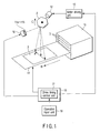
- FIG. 1 shows the configuration of a recording apparatus.
- a laser array head 10 is provided as a record head.
- the laser array head 10 is composed of a plurality of recording elements, such as laser light sources, for example, 8 semiconductor lasers 11a to 11h, arranged in a line as shown in FIG. 2 .
- Each of the semiconductor lasers 11a to 11h outputs a laser beam.
- a polygon mirror 2 is provided on the optical path of the laser beam output from each of the semiconductor lasers 11a to 11h.
- the polygon mirror 2 is driven by a motor 12 and rotates in the direction of arrow C. Rotating in the direction of arrow C, the polygon mirror 2 causes the laser beam output from each of the semiconductor lasers 11a to 11h to scan in the main scanning direction A.
- the motor 12 is rotated by a motor driving unit 13.
- the range in which the laser beam caused to scan in the main scanning direction A by the polygon mirror 2 is not limited to the surface of the thermosensitive recording medium 3.
- the laser beam could be made to scan outside the surface of the thermosensitive recording medium 3.
- thermosensitive recording medium 3 On a transport mechanism 14, for example, a thermosensitive recording medium 3 is placed.
- the thermosensitive recording medium 3 is a rewritable reversible medium which alternates between coloring and decoloring by specific temperature heating control and enables thermosensitive recording and thermosensitive erasing.
- the transport mechanism 14 transports the thermosensitive recording medium 3 in the vertical scanning direction B.
- the main scanning direction A and the vertical scanning direction B cross at right angles.
- a recording medium storage box 15 is located upstream of the transport mechanism 14.
- a plurality of thermosensitive recording mediums 3 are housed.
- the thermosensitive recording mediums 3 housed in the recording medium storage box 15 are picked up, for example, one by one and placed on the transport mechanism 14.
- a recording control unit 16 drives the laser array head 10 to cause the laser beam output from each of the semiconductor lasers 11a to 11h to scan in the main scanning direction A.
- the recording control unit 16 drives the transport mechanism 14 to transport the thermosensitive recording medium 3 in the vertical scanning direction B perpendicular to the main scanning direction A, thereby recording information onto the thermosensitive recording medium 3. That is, the recording control unit 16 gives a drive instruction to rotate the polygon mirror 2 to the motor driving unit 13.
- the recording control unit 16 gives an instruction to transport the thermosensitive recording medium 3 to the transport mechanism 14.
- the recording control unit 16 is composed of a computer including a CPU, ROM, RAM and the like.
- a drive timing control unit 17 operates as a result of the execution of a drive timing control program previously stored in, for example, the ROM.
- the drive timing control unit 17 selectively drives the individual semiconductor lasers 11a to 11h to concentrate the recording operation of each of the semiconductor lasers 11a to 11h at the information printing place, or the print dot place, on the thermosensitive recording medium 3. That is, the drive timing control unit 17 superimposes the laser beam output from each of the semiconductor laser beams 11a to 11h on one another at the same print dot on the thermosensitive recording medium 3.
- the print dot place reaches, for example, the color developing temperature (e.g., 180°C) shown in FIG. 20 .
- the drive timing control unit 17 determines for each of the semiconductor lasers 11a to 11h whether the scanning position of the laser beam output from each of the semiconductor lasers 11a to 11h has reached a position corresponding to the same print dot place on the thermosensitive recording medium 3 sequentially. If the result of the determination has shown that the scanning position of the laser beam output from each of the semiconductor lasers 11a to 11h has reached the position corresponding to the same print dot place on the thermosensitive recording medium 3 sequentially, the drive timing control unit 17 causes each of the semiconductor lasers 11a to 11h to output a laser beam sequentially, applying the individual layer beams to the same print dot place in such a manner that the beams are superimposed on one another at the print dot place sequentially.
- the drive timing control unit 17 recognizes the print dot place on the thermosensitive recording medium 3 on the basis of image data including images and characters and selectively drives each of the semiconductor lasers 11a to 11h according to the print dot place.
- the drive timing control unit 17 can vary the operation of recording onto the thermosensitive recording medium 3, that is, the speed at which the laser beam output from each of the semiconductor lasers 11a to 11h is caused to scan in the main scanning direction. A by the polygon mirror 2. For example, as the transport speed of the thermosensitive recording medium 3 increases, the scanning speed of each laser beam in the main scanning direction A increases. As the transport speed of the thermosensitive recording medium 3 decreases, the scanning speed of each laser beam in the main scanning direction A decreases. Therefore, according to the transport speed of the thermosensitive recording medium 3, the timing with which printing is done at each print dot on the thermosensitive recording medium 3 varies.
- An operation input unit 18 is for handling the start of the operation of recording on the thermosensitive recording medium 3 or the number of records.
- the operation input unit 18 may input information to be recorded on the thermosensitive recording medium 3.
- thermosensitive recording mediums 3 housed in the recording medium storage box 15 are picked up, for example, one by one and placed on the transport mechanism 14.
- the transport mechanism 14, on which the thermosensitive recording medium 3 is placed transports the thermosensitive recording medium 3 in the vertical scanning direction B. At this time, the thermosensitive recording medium 3 put on the transport mechanism 14 has no image or other data recorded on it at all.
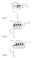
- the scanning position of the laser beam output from each of the semiconductor lasers 11a to 11h is located at a position D outside the surface of the thermosensitive recording medium 3 as shown in FIG. 3 .
- thermosensitive recording medium 3 as shown in FIG. 4 are to be printed.
- the drive timing control unit 17 When the operation of recording on the thermosensitive recording medium 3 is started, the drive timing control unit 17 recognizes, for example, the print dots d1, d3, d5, d7, d9 on the thermosensitive recording medium 3 on the basis of the image data including images and characters. According to the print dots d1, d3, d5, d7, d9, the drive timing control unit 17 selectively drives each of the semiconductor lasers 11a to 11h.
- the drive timing control unit 17 gives to the motor driving unit 13 a drive instruction to rotate the polygon mirror 2 in the direction of arrow C.
- the scanning position of the laser beam output from each of the semiconductor lasers 11a to 11h moves in the main scanning direction sequentially.
- the drive timing control unit 17 drives only the semiconductor laser 11h and does not drive the other semiconductor lasers 11a to 11g. This causes the laser beam output from the semiconductor laser 11h to be reflected by the polygon mirror 2 and applied to the print dot d1.
- the scanning position of the laser beam output from each of the semiconductor lasers 11g, 11h is located on the recording surface of the thermosensitive recording medium 3 as shown in FIG. 6 .
- the drive timing control unit 17 drives only the semiconductor laser 11g and does not drive the other semiconductor lasers 11a to 11f, 11h. This causes the laser beam output from the semiconductor laser 11g to be reflected by the polygon mirror 2 and applied to the print dot d1. As a result, at the print dot d1, the laser beam from the semiconductor laser 11g is superimposed on the laser beam from the semiconductor laser 11h which has already been applied to the print dot d1.
- the scanning position of the laser beam output from each of the semiconductor lasers 11f, 11g, 11h is located on the recording surface of the thermosensitive recording medium 3 as shown in FIG. 7 .
- the drive timing control unit 17 drives the semiconductor lasers 11f, 11h and does not drive the other semiconductor lasers 11a to 11e, 11g. This causes the laser beam output from the semiconductor laser 11h to be reflected by the polygon mirror 2 and applied to the print dot d3.
- the laser beam output from the semiconductor laser 11f is reflected by the polygon mirror 2 and applied to the print dot d1.
- the laser beam from the semiconductor laser 11f is superimposed on the laser beam from each of the semiconductor lasers 11h, 11g which has been already applied to the print dot d1.
- the drive timing control unit 17 selectively drives each of the semiconductor lasers 11a to 11h according to the print dots d1, d3, d5, d7, d9.
- the scanning position of the laser beam output from each of the semiconductor lasers 11a to 11h is located on the print face of the thermosensitive recording medium 3 as shown in FIG. 8 . That is, the scanning position of the laser beam output from the semiconductor laser 11a among the semiconductor lasers 11a to 11h is located at a position adjacent to the edge of the thermosensitive recording medium 3 and inside the edge.
- the laser beams output sequentially from each of the semiconductor lasers 11a to 11h are applied to the print dot d1 in such a manner that individual laser beams are superimposed on one another consecutively. That is, a total of 8 laser beams are applied to the print dot d1 consecutively.
- the print dot d1 receives a laser power eight times the laser power generated by the application of a laser beam from a single semiconductor laser. Consequently, heat is concentrated on the print dot d1, thereby heating the dot d1, which then reaches the color developing temperature (e.g., 180°C) shown in FIG. 20 . Accordingly, at the print dot d1, printing is completed with a sufficient density.
- the scanning position of the laser beam output from each of the semiconductor lasers 11a to 11h moves further in the main scanning direction A.
- the scanning position of the laser beam output from the semiconductor laser 11a moves to a position corresponding to the print dot d3 as shown in FIG. 9 .
- a total of 8 laser beams are applied to the print dot d3 consecutively. Accordingly, the print dot d3 similarly receives a laser power eight times the laser power generated by the application of a laser beam from a single semiconductor laser.
- each of the semiconductor lasers 11a to 11h is selectively driven according to the individual print dots d1, d3, d5, d7, d9, and the like, which causes the scanning position of the laser beam output from each of the semiconductor lasers 11a to 11h to scan by one line in the main scanning direction A.
- one line of print dots d1, d3, d5, d7, d9 is formed as shown in FIG. 4 .
- the scanning position of the laser beam output from each of the semiconductor lasers 11a to 11h is moved in the main scanning direction A and at the same time, the laser beam output from each of the semiconductor lasers 11a to 11h is applied to the same print dot, for example, each of the print dots d1, d3, d5, d7, d9 sequentially in such a manner that the individual laser beams are superimposed on one another.
- This makes it possible to realize a high-speed recording operation without a substantial rise in costs merely by using the laser array head 10 composed of the minimum necessary number of inexpensive semiconductor lasers, for example, 8 semiconductor lasers 11a to 11h, arranged in a line without using a laser apparatus, such as a high-power gas laser.
- the drive timing control unit 17 causes the laser beam output from each of the semiconductor lasers 11a to 11h to be superimposed on one another at each of the print dots d1, d3, d5, d7, d9 on the thermosensitive recording medium 3.
- the temperature at each of the print dots d1, d3, d5, d7, d9 is heated to the color developing temperature (e.g., 180°C). Accordingly, each of the semiconductor lasers 11a to 11h need not have a high laser power.
- the individual print dots d1, d3, d5, d7, d9 are printed with a sufficient density.
- the number of semiconductor lasers 11a to 11h was, for example, 8 in the explanation, the invention is not limited to this.
- the number of semiconductor lasers may be increased or decreased according to the magnitude of the laser power of each of the semiconductor lasers.
- FIG. 10 shows the configuration of a recording apparatus according to the second embodiment.
- a print recognition unit 20 is connected to the drive timing control unit 17.
- a print face sensor 21 and a print setting unit 22 are connected to the print recognition unit 20.
- the print face sensor 21 is provided in, for example, the recording medium storage box 15.
- the print face sensor 21 senses the state of the print face of the thermosensitive recording medium 3 housed in, for example, the recording medium storage box 15 and outputs a sense signal.
- an image sensor is used as the print face sensor 21.
- the operator manually sets in the print setting unit 22 information about whether the print of data (hereinafter, referred to as an existing print) is already present on the print face of the thermosensitive recording medium 3 housed in the recording medium storage box 15.
- the sense signal output from the print face sensor 21 is input to the print recognition unit 20.
- the print recognition unit 20 determines whether an existing print is present on the print face of the thermosensitive recording medium 3, on the basis of, for example, the image data on the print face of the thermosensitive recording medium 3.
- the print recognition unit 20 senses the setting state at the print setting unit 22 and, on the basis of the result of the sensing, determines whether an existing print is present on the print face of the thermosensitive recording medium 3.
- the print recognition unit 20 sends to the drive timing control unit 17 the result of determining whether an existing print is present on the print face of the thermosensitive recording medium 3.
- a temperature sensor 23 is provided in, for example, the recording medium storage box 15.
- the temperature sensor 23 senses the ambient temperature at the thermosensitive recording medium 3 housed in the recording medium storage box 15 and outputs the sense signal.
- the drive timing control unit 17 receives the result of the determination at the print recognition unit 20.
- the result of the determination shows whether or not an existing print is present on the print face of the thermosensitive recording medium 3.
- thermosensitive recording medium 3 If an existing print is present on the print face of the thermosensitive recording medium 3, for example, if print dots have already been made in all of the positions of the print dots d1 to d9 on the print face of the thermosensitive recording medium 3 as shown in FIG. 4 , the drive timing control unit 17 erases the existing print on the thermosensitive recording medium 3 and then records information.
- the drive timing control unit 17 causes each of the semiconductor lasers 11e to 11h to output a laser beam, thereby applying the laser beams to each of the print dots d1 to d9 in such a manner that the beams are superimposed on one another at each of the print dots d1 to d9 sequentially.
- each of the semiconductor lasers 11a to 11h is caused to output a laser beam, thereby applying the laser beams to each of the print dots d1 to d9 in such a manner that the beams are superimposed on one another at each of the print dots d1 to d9, which heats each of the print dots d1 to d9 on the thermosensitive recording medium 3 to the erase temperature shown in FIG. 20 .
- This causes the existing print present on the recording face to be erased.
- the drive timing control unit 17 causes each of the semiconductor lasers 11a to 11d to output a laser beam, thereby applying the laser beams to each of the print dots d1, d3, d5, d7, d9 in such a manner that the beams are superimposed on one another at each of the print dots d1, d3, d5, d7, d9.
- the drive timing control unit 17 causes each of the semiconductor lasers 11a to 11h to output a laser beam, thereby applying the laser beams to the print dot place in such a manner that the beams are superimposed on one another at the print dot place.
- the drive timing control unit 17 may change the number of semiconductor lasers 11e to 11h used to erase existing prints according to the ambient temperature at the thermosensitive recording medium 3 housed in the recording medium storage box 15. In this case, it has been determined that an existing print is present on the print face of the thermosensitive recording medium 3.
- the number of semiconductor lasers 11e to 11h used in erasing an existing print is set to 4 when the ambient temperature at the thermosensitive recording medium 3 is at a preset reference temperature.
- the number of semiconductor lasers is increased or decreased by, for example, one. Accordingly, if the ambient temperature at the thermosensitive recording medium 3 gets higher than the reference temperature by the specific temperature , the number of semiconductor lasers outputting a laser beam is decreased by one, giving three semiconductor lasers 11f to 11h. If the ambient temperature at the thermosensitive recording medium 3 gets lower than the reference temperature by the specific temperature, the number of semiconductor lasers outputting a laser beam is increased by one, giving five semiconductor lasers 11d to 11h.
- the drive timing control unit 17 causes each of a part of the semiconductor lasers 11a to 11h, for example, the semiconductor lasers 11e to 11h, to output a laser beam to each of the print dots d1 to d9, thereby applying the laser beams to each of the print dots d1 to d9 in such a manner that the beams are superimposed on one another at each of the print dots d1 to d9.
- This makes it possible to preheat the thermosensitive recording medium 3 to a temperature which has not reached the color developing temperature (e.g., 180°C) but is close to the color developing temperature.
- the preheating of the thermosensitive recording medium 3 can be realized by increasing or decreasing the number of semiconductor lasers 11e to 11h caused to output laser beams by, for example, the drive timing control unit 17 or by using semiconductor lasers 11a to 11h with a lower laser power.
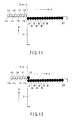
- thermosensitive recording medium 3 On the print face of the thermosensitive recording medium 3 housed in the recording medium storage box 15, for example, a print of a horizontal ruled line is already present as shown in FIG. 11 . Moreover, before the operation of recording onto the thermosensitive recording medium 3, the scanning position of the laser beam of each of the semiconductor lasers 11a to 11h is located at a position D outside the surface of the thermosensitive recording medium 3 as shown in FIG. 11 .
- the horizontal ruled line is formed of a colored line of print dots d1 to d15.
- the print face sensor 21 senses the state of the print face of the thermosensitive recording medium 3 housed in, for example, the recording medium storage box 15 and outputs the sense signal. Alternately, for example, the operator manually sets in the print setting unit 22 information about the presence of an existing print on the print face of the thermosensitive recording medium 3 housed in the recording medium storage box 15.
- the sense signal output from the print face sensor 21 is input to the print recognition unit 20.
- the print recognition unit 20 determines whether an existing print is present on the print face of the thermosensitive recording medium 3, on the basis of, for example, the image data on the print face of the thermosensitive recording medium 3.
- the print recognition unit 20 senses the setting state at the print setting unit 22 and, on the basis of the result of the sensing, determines whether an existing print is present on the print face of the thermosensitive recording medium 3.
- the print recognition 20 sends to the drive timing control unit 17 the result of determining whether an existing print is present on the print face of the thermosensitive recording medium 3.
- the drive timing control unit 17 receives from the print recognition unit 20 the result of the determination which has shown that an existing print is present on the print face of the thermosensitive recording medium 3, the drive timing control unit 17 erases the existing print on the thermosensitive recording medium 3 and then records information. Specifically, to erase the existing print, the drive timing control unit 17 drives each of a part of the semiconductor lasers 11a to 11h, for example, the semiconductor lasers 11e to 11h for each of the print dots d1 to d9 and causes each of the semiconductor lasers 11e to 11e to output a laser beam.
- the drive timing control unit 17 causes each of the semiconductor lasers 11a to 11d to output a laser beam sequentially, thereby applying the laser beams to the print dot sequentially in such a manner that the beams are superimposed on one another at the print dot.
- the drive timing control unit 17 causes each of the semiconductor lasers 11a to 11h to output a laser beam for each of the print dots d1 to d9 to erase the existing print. Then, to record information, the drive timing control unit 17 recognizes, for example, the print dots d1, d3, d5, d7, d9 on the thermosensitive recording medium 3 on the basis of image data including images and characters and, according to these print dots d1, d3, d5, d7, d9, selectively drives each of the semiconductor lasers 11a to 11d.
- the drive timing control unit 17 gives the motor driving unit 13 a drive instruction to rotate the polygon mirror 2 in the direction of arrow C.
- the scanning position of the laser beam output from each of the semiconductor lasers 11a to 11h moves in the main scanning direction sequentially.
- the existing print is first erased.
- the scanning position of the laser beam output from the semiconductor laser 11h moves to a position adjacent to the edge of the thermosensitive recording medium 3 and inside the edge as shown in FIG. 12 .
- the drive timing control unit 17 drives only the semiconductor laser 11h and does not drive the other semiconductor lasers 11a to 11g. This causes the laser beam output from the semiconductor laser 11h to be reflected by the polygon mirror 2 and applied to the print dot d1.
- the scanning position of the laser beam output from each of the semiconductor lasers 11g, 11h is located on the print face of the thermosensitive recording medium 3, as shown in FIG. 13 .
- the drive timing control unit 17 drives the semiconductor lasers 11g, 11h and does not drive the other semiconductor lasers 11a to 11f. This causes the laser beam output from each of the semiconductor lasers 11g, 11h to be reflected by the polygon mirror 2 and applied to the print dots d1, d2.
- the laser beam from the semiconductor laser 11g is superimposed on the laser beam from the semiconductor laser 11h which has been already applied to the print dot d1.
- the laser beam from the semiconductor laser 11h is applied.
- the scanning position of the laser beam output from each of the semiconductor lasers 11e to 11h is located on the print face of the thermosensitive recording medium 3, as shown in FIG. 14 .
- the drive timing control unit 17 drives the semiconductor lasers 11e to 11h and does not drive the other semiconductor lasers 11a to 11d. This causes the laser beam output from each of the semiconductor lasers 11e to 11h to be reflected by the polygon mirror 2 and applied to the print dots d1 to d4. As a result, the laser beam from each of the semiconductor lasers 11e to 11f is applied to the print dot d1 in such a manner that the beams are superimposed on one another consecutively at the print dot d1.
- the laser beam output sequentially from each of the semiconductor lasers 11e to 11h is applied to the print dot d1 in such a manner that the individual laser beams are superimposed on one another consecutively. That is, a total of 4 laser beams are applied to the print dot d1 consecutively.
- the print dot d1 receives a laser power four times the laser power generated by the application of the laser beam from a single semiconductor laser. Consequently, heat is concentrated on the print dot d1, thereby heating the dot d1, which then reaches the erase temperature shown in FIG. 20 . Accordingly, at the print dot d1, the existing print is erased as shown in FIG. 14 .
- the laser beam of each of the semiconductor lasers 11f to 11h is applied to the print dot d2 in such a manner that the beams are superimposed on one another consecutively at the print dot d2.
- the laser beam of each of the semiconductor lasers 11g, 11h is applied to the print dot d3 in such a manner that the beams are superimposed on each other consecutively at the print dot d3.
- the laser beam from the semiconductor laser 11h is applied to the print dot d4.
- the scanning position of the laser beam output from each of the semiconductor lasers 11d to 11h is located on the print face of the thermosensitive recording medium 3, as shown in FIG. 15 .
- the drive timing control unit 17 starts to drive each of the semiconductor lasers 11d to 11a to record information. That is, the drive timing control unit 17 drives each of the semiconductor lasers 11d to 11h and does not drive the other semiconductor lasers 11a to 11c.
- the laser beam output from each of the semiconductor lasers 11d to 11h is reflected by the polygon mirror 2 and applied to each of the print dots d1 to d5. Accordingly, after the print dot d1 is erased, the laser beam from the semiconductor laser 11d is first applied to the print dot d1.
- the laser beam from each of the semiconductor lasers 11f to 11h is applied to the print dot d3 in such a manner that the beams are superimposed on one another consecutively at the print dot d3.
- the laser beam from each of the semiconductor lasers 11g, 11h is applied to the print dot d4 in such a manner that the beams are superimposed on each other consecutively at the print dot d4.
- the laser beam from the semiconductor laser 11h is applied to the print dot d5.
- the scanning position of the laser beam output from each of the semiconductor lasers 11e to 11h is located on the print face of the thermosensitive recording medium 3, as shown in FIG. 16 .
- the drive timing control unit 17 drives each of the semiconductor lasers 11c, 11e to 11h and does not drive the other semiconductor lasers 11a, 11b, 11d.
- the laser beam output from each of the semiconductor lasers 11c, 11e to 11h is reflected by the polygon mirror 2 and applied to each of the print dots d1, d3 to d6. Accordingly, the laser beam from the semiconductor laser 11c is applied to the print dot d1 so as to be superimposed on the laser beam from the semiconductor laser 11d previously applied to the print dot d1.
- the laser beam of each of the semiconductor lasers 11f to 11h is applied to the print dot d4 in such a manner that the beams are superimposed on one another consecutively at the print dot d4.
- the laser beam of each of the semiconductor lasers 11g, 11h is applied to the print dot d5 in such a manner that the beams are superimposed on each other consecutively at the print dot d5.
- the laser beam from the semiconductor laser 11h is applied.
- the scanning position of the laser beam output from each of the semiconductor lasers 11a to 11h is located on the print face of the thermosensitive recording medium 3, as shown in FIG. 17 .
- the drive timing control unit 17 drives each of the semiconductor lasers 11a, 11c, 11e to 11h and does not drive the other semiconductor lasers 11b, 11d.
- the laser beam output from each of the semiconductor lasers 11a, 11c, 11e to 11h is reflected by the polygon mirror 2 and applied to each of the print dots d1, d3, d5 to d8. Accordingly, the laser beam from each of the semiconductor lasers 11a to 11d is applied to the print dot d1 consecutively.
- the laser beam output sequentially from each of the semiconductor lasers 11a to 11d is applied to the print dot d1 in such a manner that the individual laser beams are superimposed on one another consecutively.
- heat is concentrated on the print dot d1, thereby heating the dot d1, which then reaches the color developing temperature (e.g., 180°C) shown in FIG. 20 . Therefore, at the print dot d1, printing is completed with a sufficient density.
- the laser beam from the semiconductor laser 11c is first applied to the print dot d3.
- the laser beam from each of the semiconductor lasers 11f to 11h is applied to the print dot d6 in such a manner that the beams are superimposed on one another consecutively at the print dot d6.
- the laser beam from each of the semiconductor lasers 11g, 11h is applied to the print dot d7 in such a manner that the beams are superimposed on each other consecutively at the print dot d7.
- the laser beam from the semiconductor laser 11h is applied to the print dot d8 in such a manner that the beams are superimposed on each other consecutively at the print dot d7.
- the print face sensor 21 senses the state where there is no print on the thermosensitive recording medium 3 and outputs the sense signal.
- the operator manually inputs to the print setting unit 22 information that there is no print on the print face of the thermosensitive recording medium 3.
- the print recognition unit 20 determines that there is no print on the print face of the thermosensitive recording medium 3, on the basis of, for example, image data on the print face of the thermosensitive recording medium 3.
- the print recognition unit 20 determines that there is no print on the print face of the thermosensitive recording medium 3.
- the print recognition unit 20 sends to the drive timing control unit 17 the result of determining that there is no print on the print face of the thermosensitive recording medium 3.
- the drive timing control unit 17 causes each of the semiconductor lasers 11a to 11h to output a laser beam sequentially when the scanning position of the laser beam output from each of the semiconductor lasers 11a to 11h has reached a position corresponding to the print dot place on the thermosensitive recording medium 3 sequentially as shown in FIG. 3 and FIGS. 5 to 9 , thereby applying the laser beams to the print dot place in such a manner that the beams are superimposed on one another at the print dot place.
- one line of print dots d1, d3, d5, d7, d9 is formed as shown in, for example, FIG. 4 .
- the temperature sensor 23 senses the ambient temperature at the thermosensitive recording medium 3 housed in the recording medium storage box 15 and outputs the sense signal. Receiving the sense signal output from the temperature sensor 23, the drive timing control unit 17 changes the number of semiconductor lasers 11e to 11h used to erase existing prints according to the ambient temperature at the thermosensitive recording medium 3 housed in the recording medium storage box 15. For example, if the ambient temperature at the thermosensitive recording medium 3 becomes higher than the reference temperature by the specific temperature, the drive timing control unit 17 decreases the number of semiconductor lasers to output a laser beam by one, giving three semiconductor lasers 11f to 11h. If the ambient temperature at the thermosensitive recording medium 3 becomes lower than the reference temperature by the specific temperature, the drive timing control unit 17 increases the number of semiconductor lasers to output a laser beam by one, giving five semiconductor lasers 11d to 11h.
- the laser beam output from each of a part of the semiconductor lasers 11a to 11h, for example, the semiconductor lasers 11e to 11h shown in FIG. 2 is applied to each of the print dots d1 to d9 in such a manner that the beams are superimposed on one another at each of the print dots d1 to d9.
- the print face of the thermosensitive recording medium 3 is heated to the erase temperature shown in FIG. 20 , which enables the existing print present on the recording face to be erased.
- each of the semiconductor lasers 11a to 11d is caused to output a laser beam.
- the individual laser beams are applied to each of the print dots d1, d3, d5, d7, d9 in such a manner that the beams are superimposed on one another sequentially.
- one line of print dots d1, d3, d5, d7, d9 shown in, for example, FIG. 4 is formed on the print face of the thermosensitive recording medium 3.
- the second embodiment produces the same effect as that of the first embodiment. That is, with the second embodiment, it is possible to realize a high-speed recording operation without a substantial rise in costs merely by using the laser array head 10 composed of the minimum necessary number of inexpensive semiconductor lasers, for example, 8 semiconductor lasers 11a to 11h, arranged in a line without using a laser apparatus, such as a high-power gas laser.
- the print recognition unit 20 determines whether there is an existing print on the print face of the thermosensitive recording medium 3. Thus, if there is no existing print on the print face of the thermosensitive recording medium 3, the print face of the thermosensitive recording medium 3 can be raised to the color developing temperature, thereby recording image data including images and characters, as in the first embodiment. If there is an existing print on the print face of the thermosensitive recording medium 3, after the existing print is erased, the print face of the thermosensitive recording medium 3 can be raised to the color developing temperature, thereby recording image data including images and characters.
- thermosensitive recording medium 3 information can be recorded automatically on the print face of the thermosensitive recording medium 3 by switching between a case where there is an existing print or case where there is no existing print on the print face of the thermosensitive recording medium 3 according to the state of the print face of the thermosensitive recording medium 3.
- thermosensitive recording medium 3 If there is no existing print on the print face of the thermosensitive recording medium 3, since each of a part of the semiconductor lasers 11a to 11h, for example, each of the semiconductor lasers 11e to 11h shown in FIG. 2 , is not driven for each of the print dots d1 to d15 to output a laser beam, the power consumption can be reduced.
- the number of semiconductor lasers 11e to 11h used to erase existing prints is changed. This reduces the number of semiconductor lasers to output a laser beam by at least one when the apparatus is used in a high-temperature environment. For example, the laser beam output from each of the three semiconductor lasers 11f to 11h is applied to a print dot where an existing print is present, thereby enabling the existing print to be erased.
- thermosensitive recording medium is composed of a protective layer/a color-producing layer/a base material
- it may be composed of a protective layer/a photothermal conversion layer/a color-producing layer/a base material.
- it is possible to concentrate light by superimposing laser beams on one another, convert the concentrated light into heat with the photothermal conversion layer, and concentrate the resulting heat.
- the number of semiconductor lasers 11a to 11h has been, for example, 8, the invention is not limited to this.
- the number of semiconductor lasers 11a to 11h may be set according to the magnitude of the laser power of each of the semiconductor lasers 11a to 11h or the temperature environment of the apparatus.
- the laser power of each of the semiconductor lasers 11a to 11h may be varied according to the number of semiconductor lasers 11a to 11h.
- the laser array head 10 which forms each print dot by applying a laser beam onto the thermosensitive recording medium 3 has been used, the invention is not limited to this.
- the invention may be applied to an ink-jet recording apparatus which forms an image by dropping, for example, black (K), cyan (C), magenta (M), and yellow (Y) inks on a recording medium, such as recording paper.
- the KCMY inks output from the ink-jet record head are dropped separately on the same print dot, such as each of the print dots d1, d3, d5, d7, d9, on the recording medium in such a manner that the inks are superimposed on one another sequentially at the dot at the same time that the ink-jet record head is moved in the main scanning direction A1.
- This enables a print dot d1 with the optimum density to be formed by dropping, for example, a number, K, of color inks on the print dot d1 in such a manner that the inks are superimposed on one another sequentially at the dot.
Landscapes
- Health & Medical Sciences (AREA)
- General Health & Medical Sciences (AREA)
- Toxicology (AREA)
- Electronic Switches (AREA)
- Heat Sensitive Colour Forming Recording (AREA)
- Dot-Matrix Printers And Others (AREA)
- Facsimile Scanning Arrangements (AREA)
Applications Claiming Priority (1)
| Application Number | Priority Date | Filing Date | Title |
|---|---|---|---|
| JP2007014111A JP2008179052A (ja) | 2007-01-24 | 2007-01-24 | 記録装置及びその方法 |
Publications (2)
| Publication Number | Publication Date |
|---|---|
| EP1950044A2 true EP1950044A2 (de) | 2008-07-30 |
| EP1950044A3 EP1950044A3 (de) | 2009-08-12 |
Family
ID=39133863
Family Applications (1)
| Application Number | Title | Priority Date | Filing Date |
|---|---|---|---|
| EP08001126A Withdrawn EP1950044A3 (de) | 2007-01-24 | 2008-01-22 | Aufzeichnungsvorrichtung mit Aufnahmekopf und Aufzeichnungsverfahren unter Verwendung des Aufnahmekopfs |
Country Status (4)
| Country | Link |
|---|---|
| US (1) | US8031218B2 (de) |
| EP (1) | EP1950044A3 (de) |
| JP (1) | JP2008179052A (de) |
| CN (1) | CN101229730A (de) |
Families Citing this family (2)
| Publication number | Priority date | Publication date | Assignee | Title |
|---|---|---|---|---|
| JP7435088B2 (ja) * | 2019-03-20 | 2024-02-21 | 株式会社リコー | レーザ記録装置、レーザ記録方法、及びレーザ記録用レーザ照射プログラム |
| JP2020151985A (ja) * | 2019-03-20 | 2020-09-24 | 株式会社リコー | レーザ記録装置、レーザ記録方法、及びレーザ記録用レーザ照射プログラム |
Citations (1)
| Publication number | Priority date | Publication date | Assignee | Title |
|---|---|---|---|---|
| JP2001341429A (ja) | 2000-03-31 | 2001-12-11 | Ricoh Co Ltd | 可逆性感熱記録媒体の初期化方法、書換方法、及び書換、初期化装置 |
Family Cites Families (15)
| Publication number | Priority date | Publication date | Assignee | Title |
|---|---|---|---|---|
| JPS6278964A (ja) | 1985-10-02 | 1987-04-11 | Copal Electron Co Ltd | 熱記録装置 |
| US5089908A (en) * | 1990-06-29 | 1992-02-18 | Xerox Corporation | Plywood suppression in ROS systems |
| JPH04197647A (ja) * | 1990-11-29 | 1992-07-17 | Toshiba Corp | 記録装置 |
| JPH05238023A (ja) * | 1992-02-27 | 1993-09-17 | Fuji Photo Film Co Ltd | 熱記録装置 |
| JP3446316B2 (ja) | 1993-11-16 | 2003-09-16 | 凸版印刷株式会社 | レーザ記録方法及びレーザ記録装置 |
| EP0795997A1 (de) * | 1996-03-14 | 1997-09-17 | Agfa-Gevaert N.V. | Herstellung von Bildern mit kontinuierlichen Tönen durch sequentielle Belichtung eines thermographischen Materials mittels eines Satzes von Strahlenbündeln |
| JPH1084460A (ja) * | 1996-09-09 | 1998-03-31 | Fuji Photo Film Co Ltd | 画像読取再生装置 |
| US5923825A (en) * | 1996-12-04 | 1999-07-13 | Eastman Kodak Company | Data transmission for a sparse array printhead |
| US5835280A (en) * | 1997-04-22 | 1998-11-10 | Eastman Kodak Company | F-θ lens |
| JP4291945B2 (ja) * | 1999-11-05 | 2009-07-08 | 富士フイルム株式会社 | 記録方法及び記録装置 |
| JP2001277734A (ja) * | 2000-03-29 | 2001-10-10 | Minolta Co Ltd | 熱可逆性記録媒体への記録方法及び記録装置 |
| JP5040049B2 (ja) * | 2000-08-04 | 2012-10-03 | 大日本印刷株式会社 | 可逆性感熱記録媒体の記録消去装置 |
| US7283149B2 (en) * | 2002-05-31 | 2007-10-16 | Seiko Epson Corporation | Optical head and image forming apparatus employing the same |
| JP2004249541A (ja) * | 2003-02-19 | 2004-09-09 | Sony Corp | 可逆性多色記録媒体の記録装置 |
| JP4335017B2 (ja) | 2004-01-08 | 2009-09-30 | 株式会社リコー | 熱可逆記録媒体、並びに、熱可逆記録部材及び画像処理方法 |
-
2007
- 2007-01-24 JP JP2007014111A patent/JP2008179052A/ja active Pending
-
2008
- 2008-01-22 EP EP08001126A patent/EP1950044A3/de not_active Withdrawn
- 2008-01-23 US US12/011,035 patent/US8031218B2/en not_active Expired - Fee Related
- 2008-01-24 CN CNA2008100088290A patent/CN101229730A/zh active Pending
Patent Citations (1)
| Publication number | Priority date | Publication date | Assignee | Title |
|---|---|---|---|---|
| JP2001341429A (ja) | 2000-03-31 | 2001-12-11 | Ricoh Co Ltd | 可逆性感熱記録媒体の初期化方法、書換方法、及び書換、初期化装置 |
Also Published As
| Publication number | Publication date |
|---|---|
| US20080174654A1 (en) | 2008-07-24 |
| US8031218B2 (en) | 2011-10-04 |
| JP2008179052A (ja) | 2008-08-07 |
| CN101229730A (zh) | 2008-07-30 |
| EP1950044A3 (de) | 2009-08-12 |
Similar Documents
| Publication | Publication Date | Title |
|---|---|---|
| EP0468237B1 (de) | Verfahren und Vorrichtung für die wiedereinschreibbare und löschbare Aufzeichnung und wiedereinschreibbarer Aufzeichnungsfilm | |
| TWI389801B (zh) | 標記控制裝置、雷射應用裝置、標記控制方法、以及具有標記控制程式之電腦可讀取記錄媒體 | |
| US20010052920A1 (en) | Ink jet printer and ink jet printing method | |
| JP2005271480A (ja) | 画像記録装置及び画像記録方法 | |
| JP2002011860A (ja) | インクジェットプリンタ及びプリント方法 | |
| US8031218B2 (en) | Recording apparatus with a record head and recording method using the record head | |
| JP2004188829A (ja) | 可逆性多色記録媒体の記録装置 | |
| TWI303812B (en) | Disc recorder with printer | |
| JPH11348337A (ja) | サーマルプリント方法 | |
| JP5854472B2 (ja) | 画像形成装置 | |
| JPH05261953A (ja) | サーマルヘッド | |
| JP2003072239A (ja) | 両面画像記録方法 | |
| JP2002103662A (ja) | 画像記録装置及び画像記録方法 | |
| JP3048484B2 (ja) | カラーシリアルプリンタ | |
| JP2001096840A (ja) | プリンタ | |
| JP2008137244A (ja) | 非接触光書き込み装置 | |
| KR20220165979A (ko) | 폴리건 미러 스캐너를 이용한 레이저 라벨프린터 및 이를 이용한 라벨 인쇄 방법 | |
| JP2004188828A (ja) | 可逆性多色記録媒体の記録装置 | |
| JP2003300339A (ja) | 熱転写記録装置および熱転写記録方法 | |
| JPH0569566A (ja) | 多色感熱記録装置 | |
| US6778199B2 (en) | Thermal transfer recording device and method therefor | |
| JP2009214455A (ja) | 記録装置及びその方法 | |
| JP2009101669A (ja) | ラインヘッド消去記録装置及びその制御方法 | |
| JPH11138997A (ja) | 画像記録媒体および画像記録方法 | |
| JP2004136608A (ja) | 感熱プリンタ及び感熱プリント方法 |
Legal Events
| Date | Code | Title | Description |
|---|---|---|---|
| PUAI | Public reference made under article 153(3) epc to a published international application that has entered the european phase |
Free format text: ORIGINAL CODE: 0009012 |
|
| 17P | Request for examination filed |
Effective date: 20080122 |
|
| AK | Designated contracting states |
Kind code of ref document: A2 Designated state(s): AT BE BG CH CY CZ DE DK EE ES FI FR GB GR HR HU IE IS IT LI LT LU LV MC MT NL NO PL PT RO SE SI SK TR |
|
| AX | Request for extension of the european patent |
Extension state: AL BA MK RS |
|
| PUAL | Search report despatched |
Free format text: ORIGINAL CODE: 0009013 |
|
| AK | Designated contracting states |
Kind code of ref document: A3 Designated state(s): AT BE BG CH CY CZ DE DK EE ES FI FR GB GR HR HU IE IS IT LI LT LU LV MC MT NL NO PL PT RO SE SI SK TR |
|
| AX | Request for extension of the european patent |
Extension state: AL BA MK RS |
|
| AKX | Designation fees paid |
Designated state(s): DE FR GB |
|
| STAA | Information on the status of an ep patent application or granted ep patent |
Free format text: STATUS: THE APPLICATION IS DEEMED TO BE WITHDRAWN |
|
| 18D | Application deemed to be withdrawn |
Effective date: 20100213 |