EP1950574B1 - Dispositif de mesure d'un courant électrique passant dans un conducteur électrique - Google Patents
Dispositif de mesure d'un courant électrique passant dans un conducteur électrique Download PDFInfo
- Publication number
- EP1950574B1 EP1950574B1 EP08000945A EP08000945A EP1950574B1 EP 1950574 B1 EP1950574 B1 EP 1950574B1 EP 08000945 A EP08000945 A EP 08000945A EP 08000945 A EP08000945 A EP 08000945A EP 1950574 B1 EP1950574 B1 EP 1950574B1
- Authority
- EP
- European Patent Office
- Prior art keywords
- magnetic field
- magnetic
- air gap
- measuring
- current
- Prior art date
- Legal status (The legal status is an assumption and is not a legal conclusion. Google has not performed a legal analysis and makes no representation as to the accuracy of the status listed.)
- Active
Links
Images

Classifications
-
- G—PHYSICS
- G01—MEASURING; TESTING
- G01R—MEASURING ELECTRIC VARIABLES; MEASURING MAGNETIC VARIABLES
- G01R15/00—Details of measuring arrangements of the types provided for in groups G01R17/00 - G01R29/00, G01R33/00 - G01R33/26 or G01R35/00
- G01R15/14—Adaptations providing voltage or current isolation, e.g. for high-voltage or high-current networks
- G01R15/20—Adaptations providing voltage or current isolation, e.g. for high-voltage or high-current networks using galvano-magnetic devices, e.g. Hall-effect devices, i.e. measuring a magnetic field via the interaction between a current and a magnetic field, e.g. magneto resistive or Hall effect devices
-
- G—PHYSICS
- G01—MEASURING; TESTING
- G01R—MEASURING ELECTRIC VARIABLES; MEASURING MAGNETIC VARIABLES
- G01R15/00—Details of measuring arrangements of the types provided for in groups G01R17/00 - G01R29/00, G01R33/00 - G01R33/26 or G01R35/00
- G01R15/14—Adaptations providing voltage or current isolation, e.g. for high-voltage or high-current networks
- G01R15/20—Adaptations providing voltage or current isolation, e.g. for high-voltage or high-current networks using galvano-magnetic devices, e.g. Hall-effect devices, i.e. measuring a magnetic field via the interaction between a current and a magnetic field, e.g. magneto resistive or Hall effect devices
- G01R15/207—Constructional details independent of the type of device used
-
- G—PHYSICS
- G01—MEASURING; TESTING
- G01R—MEASURING ELECTRIC VARIABLES; MEASURING MAGNETIC VARIABLES
- G01R33/00—Arrangements or instruments for measuring magnetic variables
- G01R33/02—Measuring direction or magnitude of magnetic fields or magnetic flux
- G01R33/0206—Three-component magnetometers
-
- G—PHYSICS
- G01—MEASURING; TESTING
- G01R—MEASURING ELECTRIC VARIABLES; MEASURING MAGNETIC VARIABLES
- G01R31/00—Arrangements for testing electric properties; Arrangements for locating electric faults; Arrangements for electrical testing characterised by what is being tested not provided for elsewhere
- G01R31/36—Arrangements for testing, measuring or monitoring the electrical condition of accumulators or electric batteries, e.g. capacity or state of charge [SoC]
- G01R31/364—Battery terminal connectors with integrated measuring arrangements
Definitions
- the invention relates to a device for measuring an electrical current flowing through an electrical conductor with a measuring device arranged in the vicinity of the electrical conductor, which detects the magnetic field generated by the electric current and provides an electrical signal corresponding to the current intensity.
- the publication US 2003/017753 A1 discloses a battery terminal with an integrated current sensor, which is closed by the measurement of a magnetic field on a current flowing through the electrical conductor and the magnetic field generating current.
- the current sensor may be in galvanic contact with the corresponding battery post for measuring the current, or may be formed with a current sensor based on a Hall sensor.
- the output signals of the Hall sensor are evaluated, and it can be determined in dependence on the output signal of the current flowing through the electrical conductor current.
- a 3-D vertical Hall magnetic-field sensor in CMOS technology by Paranjape, Filanovsky and Ristic, Sensors and Actuators A, published July 1992 (XP 000297419) discloses the arrangement of a sensor used as a current sensor or generally as a Magnetic field sensor can be used.
- a magnetic field to be detected which is formed in a three-dimensional space is detected by the magnetic field sensor in all three dimensions, so that a respective component of the magnetic field in three spatial directions X, Y and Z is formed.
- the magnetic field sensor comprises respective Hall sensors for the three-dimensional detection of the magnetic field, with which one of the components is detected.
- the output signals of the respective Hall sensors denote a magnetic field intensity prevailing in this spatial direction.
- Different embodiments of the magnetic field sensor are provided, whereby different measurements and results are possible depending on the design. Mutual influences of the respective measurement results in certain spatial directions by other spatial directions should be avoided or reduced.
- the invention has the object, a device of the type mentioned in such a way that an accurate measurement of the current flowing in the electrical conductor electrical current is achieved.
- a measuring device which is arranged in the vicinity of the electrical conductor and which can detect the magnetic field generated by the current-carrying conductor in three orthogonal spatial directions.
- the magnetic sensor device has the three orthogonal spatial directions associated magnetic field-sensitive transducer or sensors. These emit electrical signals proportional to the three orthogonal field strength components of the magnetic field.
- the measuring device has at least one core of magnetic material with at least one air gap, in which a magnetic field corresponding to the current intensity is generated.
- the magnetic sensor device is arranged in at least one air gap or in the vicinity of the air gap for detecting the generated magnetic field.
- the air gap can be generated by appropriate shaping of the air gap limiting interfaces a homogeneous or inhomogeneous magnetic field.
- the magnetic field strengths measured in each case in the orthogonal spatial directions can be assigned to measuring ranges with different measuring sensitivities. Furthermore, it is possible to arrange measuring devices in a plurality of air gaps and to associate the respective measuring devices with measuring ranges having different measuring sensitivities. It is also possible to assign different regions of the magnetization curve of the magnetic material to measuring regions with different measuring sensitivity.
- Cores may be provided which have a plurality of air gaps. However, it is also possible to provide a plurality of cores, between which a plurality of air gaps are formed. Furthermore, cores can be provided from different magnetic materials. In this case, the respective core can have at least one air gap and at least one air gap can be formed between the cores.
- the different measuring ranges can also be provided in the air gaps or in the vicinity of the air gaps measuring devices.
- the current-carrying electrical conductor or the current-carrying electrical conductors can be guided through holes and / or recesses of the at least one core. It is also possible to guide the conductor around the core or around projections provided on the core or other core part.
- the device is designed so that it is suitable for use on a power connection element, for example on a cable clamp or pole connection terminal for battery poles in vehicles.
- the magnetic sensor device contains magnetic-field-sensitive transducers assigned to the orthogonal spatial directions, for example magnetoresistive transducers, Hall elements, magnetotransistors or the like.
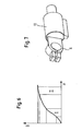
- FIG. 1 schematically an embodiment of the invention is shown.
- This embodiment includes a magnetic circuit 8 formed by a core of magnetic material.
- Magnetically hard or soft materials in particular ferrites, can be used as the magnetic material for the magnetic circuit 8.
- the magnetic circle is shown rectangular. It is also possible to use ring cores to form the to use magnetic circuit. Instead of a simple magnetic circuit, branched magnetic circuits can also be used.
- an air gap 3 is present in the embodiment. It is also possible to provide two or more air gaps in the magnetic circuit.
- the respective air gap 3 is bounded by boundary surfaces 4 and 5.
- boundary surfaces 4 and 5 By appropriate shaping of the interfaces 4 and 5, homogeneous or inhomogeneous magnetic fields can be formed in the air gap 3.
- the magnetic field formed in the respective air gap 3 is proportional to a current, in particular direct current, which flows in an electrical conductor 1.
- the magnetic circuit 8 is arranged in the vicinity of this electrical conductor 1 so that the field lines of the magnetic field formed by the electrical conductor 1 pass through the magnetic circuit 8.
- the electrical conductor 1 wraps around a leg of the magnetic circuit 8 in the form of a coil.
- the electrical conductor 1 may be guided through a bore of the toroidal core. It is also possible to arrange the conductor 1 in recesses, in particular in recesses of the toroidal core in the form of a loop or coil.
- a substantially homogeneous magnetic field can be generated by flat, mutually parallel boundary surfaces 4 and 5.
- the magnetic field is inhomogeneous and the field lines have a curved course.
- an inhomogeneous magnetic field is formed in the air gap 3.
- the boundary surfaces 4 and 5 have different shapes.
- one of the two boundary surfaces is arranged obliquely opposite to the other boundary surface.
- the boundary surfaces 4 and 5 curved, in particular Karlottenform, wherein instead of in the FIG. 3 shown convex curvature and a concave curvature can be used.
- both boundary surfaces 4 and 5 are arranged obliquely with respect to the middle plane of the air gap 3.
- the two planar boundary surfaces 4 and 5 are arranged offset to one another.
- other forms of the boundary surfaces can be used, with a combined application of the in the FIGS. 2 to 5 arrangements shown can also be used.
- the respective air gap 3 can be formed in the core material or between adjacent cores.
- a magnetic sensor device 2 is arranged in the current measuring device 7, which detects the magnetic field in three orthogonal spatial directions (X Y Z).
- the magnetic sensor device has the three orthogonal spatial directions (X Y Z) associated magnetic field-sensitive transducer or sensors.
- Each of these sensors generates an electrical signal which is proportional to the magnetic field component in its associated spatial direction.
- These signals are fed to an evaluation device 9, in particular an electronic evaluation device, for example a microprocessor. This evaluates the electrical signals and forms display signals for display devices 10, 11, 12.
- These display devices can provide the three orthogonal spatial directions associated displays.
- the magnetic field sensor device 2 is arranged in an inhomogeneous magnetic field region of the air gap 3.
- the air gap or the air gaps can be formed so that inhomogeneous magnetic fields are generated.
- the display devices 10, 11, 12 are assigned to the respective spatial directions (XYZ) of the field strength components, different measured values are indicated in the display devices for the current flowing in the electrical conductor 1.
- the changes in the field strength components of the magnetic field lying in the respective spatial directions change differently at the location of the associated transducers or sensors of the magnetic sensor device 2. For the measurements in the three spatial directions, therefore, different current sensitivities result in the measured values and the respective displays for these measured values.
- FIG. 7 is a Polan gleichklemme 6 for a power cable, which is to be connected to a battery terminal of a vehicle battery shown.
- a housing 13 an embodiment of the invention is installed and fixed to the pole terminal 6.
- This embodiment is representative of other possible uses of the device according to the invention in the arrangement in the immediate vicinity of current-carrying conductors whose current is to be measured.
- the device according to the invention can be fastened in a housing, in particular in the region of power connection elements.
Landscapes
- Physics & Mathematics (AREA)
- General Physics & Mathematics (AREA)
- Condensed Matter Physics & Semiconductors (AREA)
- Measuring Instrument Details And Bridges, And Automatic Balancing Devices (AREA)
- Measurement Of Current Or Voltage (AREA)
- Measuring Magnetic Variables (AREA)
Claims (10)
- Dispositif pour la mesure d'un courant électrique circulant à travers un conducteur électrique comprenant un équipement de mesure disposé à proximité du conducteur électrique, lequel détecte le champ magnétique produit par le courant électrique et délivre un signal électrique correspondant à l'intensité du courant, caractérisé en ce que l'équipement de mesure présente un équipement à capteur magnétique (2) détectant le champ magnétique dans trois directions spatiales orthogonales, l'équipement à capteur magnétique (2) présentant des convertisseurs ou des capteurs sensibles au champ magnétique associés aux trois directions spatiales orthogonales (X, Y, Z), et les intensités de champ magnétique mesurées dans les directions spatiales orthogonales (X, Y, Z) étant associées respectivement à des plages de mesure avec différentes sensibilités de mesure.
- Dispositif selon la revendication 1,
caractérisé en ce que l'équipement de mesure (7) présente au moins un circuit magnétique (8) en matériau magnétique comprenant au moins un entrefer (3), dans lequel un champ magnétique correspondant à l'intensité de courant est produit, et que l'équipement à capteur magnétique (2) est disposé dans au moins un entrefer (3) ou à proximité de l'entrefer (3) pour détecter le champ magnétique présent dans l'entrefer (3) ou à proximité de l'entrefer (3). - Dispositif selon la revendication 2,
caractérisé en ce que les surfaces délimitant l'entrefer (3) d'un noyau formant le circuit magnétique (8) sont des surfaces limites (4 et 5) pour produire un champ magnétique homogène dans l'entrefer (3). - Dispositif selon la revendication 2,
caractérisé en ce que les surfaces limites (4 et 5) délimitant l'entrefer (3) sont conçues pour produire un champ magnétique inhomogène dans l'entrefer (3). - Dispositif selon l'une quelconque des revendications 2 à 4,
caractérisé en ce que des équipements à capteur magnétique (2) associés à différentes plages de mesure comprenant différentes sensibilités de mesure sont disposés dans plusieurs entrefers (3) ou à proximité de ces derniers. - Dispositif selon l'une quelconque des revendications 2 à 5,
caractérisé en ce que des plages de mesure comprenant différentes sensibilités de mesure sont associées aux différentes plages de la courbe de saturation du matériau magnétique respectif du ou des circuits magnétiques (8). - Dispositif selon l'une quelconque des revendications 2 à 6,
caractérisé en ce que deux noyaux ou plus sont prévus pour former le circuit magnétique (8) et un ou plusieurs entrefers (3) sont formés entre les noyaux. - Dispositif selon la revendication 7,
caractérisé en ce que les noyaux sont réalisés en des matériaux magnétiques différents. - Dispositif selon l'une quelconque des revendications 1 à 8,
caractérisé en ce que le conducteur électrique en charge (1) est guidé à travers des trous et/ou des évidements ou autour de saillies d'au moins un noyau dans lequel est produit le champ magnétique. - Dispositif selon l'une quelconque des revendications 1 à 9,
caractérisé en ce qu'il convient à la fixation sur un élément de raccordement électrique, en particulier à un collier de câble ou à une borne de raccordement de pôle, en particulier pour des batteries de véhicule.
Applications Claiming Priority (1)
| Application Number | Priority Date | Filing Date | Title |
|---|---|---|---|
| DE102007003830A DE102007003830B4 (de) | 2007-01-25 | 2007-01-25 | Vorrichtung zur Messung eines durch einen elektrischen Leiter fließenden elektrischen Stroms |
Publications (3)
| Publication Number | Publication Date |
|---|---|
| EP1950574A2 EP1950574A2 (fr) | 2008-07-30 |
| EP1950574A3 EP1950574A3 (fr) | 2010-12-01 |
| EP1950574B1 true EP1950574B1 (fr) | 2012-03-14 |
Family
ID=39405991
Family Applications (1)
| Application Number | Title | Priority Date | Filing Date |
|---|---|---|---|
| EP08000945A Active EP1950574B1 (fr) | 2007-01-25 | 2008-01-18 | Dispositif de mesure d'un courant électrique passant dans un conducteur électrique |
Country Status (7)
| Country | Link |
|---|---|
| US (1) | US8018221B2 (fr) |
| EP (1) | EP1950574B1 (fr) |
| JP (1) | JP5597788B2 (fr) |
| KR (1) | KR101395383B1 (fr) |
| CN (1) | CN101241147B (fr) |
| AT (1) | ATE549629T1 (fr) |
| DE (1) | DE102007003830B4 (fr) |
Cited By (1)
| Publication number | Priority date | Publication date | Assignee | Title |
|---|---|---|---|---|
| WO2025078484A1 (fr) * | 2023-10-10 | 2025-04-17 | Ast (Advanced Sensor Technologies) International Asset Gmbh | Dispositif de mesure du courant électrique circulant dans un conducteur électrique, et dispositif de charge pour véhicule électrique |
Families Citing this family (14)
| Publication number | Priority date | Publication date | Assignee | Title |
|---|---|---|---|---|
| JP2010223929A (ja) * | 2009-03-19 | 2010-10-07 | Kohshin Electric Corp | 磁気コア及びこれを用いた電流センサ |
| AU2009342863B2 (en) * | 2009-03-23 | 2013-09-05 | Actherm Inc. | Analytical Strip and the Manufacturing Method Thereof |
| DE202010008832U1 (de) | 2010-10-19 | 2012-01-20 | Z-Wave Europe Gmbh | Einrichtung zur Erfassung der elektrischen Leistung, insbesondere der Wirkleistung und/oder der elektrischen Arbeit eines Verbrauchers |
| WO2012098665A1 (fr) * | 2011-01-20 | 2012-07-26 | 富士通株式会社 | Barrette de connexion et système de mesure de puissance électrique |
| EP2515125B1 (fr) * | 2011-04-21 | 2017-02-01 | Abb Ag | Capteur de courant doté d'un noyau magnétique |
| JP2014006181A (ja) * | 2012-06-26 | 2014-01-16 | Aisin Seiki Co Ltd | 電流センサ |
| DE102012110869B4 (de) * | 2012-11-13 | 2016-03-03 | Gira Giersiepen Gmbh & Co. Kg | Flusskonzentrator für eine Sensoranordnung sowie eine entsprechende Sensoranordnung und eine Steckdose |
| FR3002204B1 (fr) * | 2013-02-15 | 2015-02-20 | Hutchinson | Amortisseur instrumente et systeme de suivi de performance comprenant un tel amortisseur. |
| TWI644112B (zh) | 2016-12-14 | 2018-12-11 | 旺玖科技股份有限公司 | 用以感測電氣設備使用狀態之感測器及其感測方法 |
| FR3050081B1 (fr) * | 2016-04-12 | 2018-03-23 | Schneider Electric Industries Sas | Dispositif de detection d'un courant de defaut |
| CN106093733B (zh) * | 2016-07-30 | 2019-01-11 | 清华大学 | 电晕电流的测量装置及用其进行多点电晕电流定位方法 |
| CN108205085A (zh) * | 2016-12-19 | 2018-06-26 | 旺玖科技股份有限公司 | 用以感测电气设备使用状态的传感器及其感测方法 |
| JP1746045S (ja) * | 2022-09-07 | 2023-06-12 | 電流測定モジュール | |
| DE102023116476A1 (de) * | 2023-06-22 | 2024-12-24 | Vacuumschmelze Gmbh & Co. Kg | Polschuh-formung |
Family Cites Families (14)
| Publication number | Priority date | Publication date | Assignee | Title |
|---|---|---|---|---|
| DD257719A1 (de) | 1987-02-13 | 1988-06-22 | Liebknecht Transformat | Schaltungsanordnung fuer eine ueberstromschutzeinrichtung in hochspannungs- oder hochleistungspruefanlagen |
| JPH03229161A (ja) * | 1990-02-05 | 1991-10-11 | Furukawa Electric Co Ltd:The | 自動車用電流センサ |
| EP0521250A3 (en) * | 1991-07-03 | 1993-01-13 | Landis & Gyr Betriebs Ag | Current measuring transducer using a magnetic field sensor |
| JP3007553B2 (ja) * | 1995-03-24 | 2000-02-07 | 日本レム株式会社 | 電流センサ |
| EP0947846B1 (fr) * | 1998-03-30 | 2005-11-02 | Sentron Ag | Capteur de champ magnétique |
| WO2000043795A1 (fr) * | 1999-01-21 | 2000-07-27 | Tdk Corporation | Detecteur de courant |
| US6304082B1 (en) * | 1999-07-13 | 2001-10-16 | Honeywell International Inc. | Printed circuit boards multi-axis magnetometer |
| DE10104453A1 (de) * | 2001-02-01 | 2002-08-08 | Philips Corp Intellectual Pty | Anordnung zum Messen der magnetischen Feldstärke |
| US6544078B2 (en) * | 2001-07-18 | 2003-04-08 | Midtronics, Inc. | Battery clamp with integrated current sensor |
| DE102005024075B4 (de) * | 2005-05-25 | 2007-04-12 | Lisa Dräxlmaier GmbH | Verfahren und Vorrichtung zur Messung eines in einem elektrischen Leiter fließenden Stroms |
| JP5052006B2 (ja) * | 2005-12-28 | 2012-10-17 | 株式会社日本自動車部品総合研究所 | 燃料電池の電流測定システムおよび電流測定方法 |
| EP1811311B1 (fr) * | 2006-01-19 | 2016-08-31 | Melexis Technologies NV | Dispositif pour mesurer le courant |
| JP2007315756A (ja) * | 2006-05-23 | 2007-12-06 | Kansai Electric Power Co Inc:The | 磁気抵抗効果素子を用いた電流センサおよびその検出回路 |
| DE102006032762B8 (de) * | 2006-07-14 | 2009-10-08 | Lisa Dräxlmaier GmbH | Verfahren zur Messung eines in einem elektrischen Leiter fließenden Stromes und Verwendung des Verfahrens sowie einer Vorrichtung zur Überwachung von Strömen im Bordnetz eines Kraftfahrzeugs |
-
2007
- 2007-01-25 DE DE102007003830A patent/DE102007003830B4/de not_active Expired - Fee Related
-
2008
- 2008-01-18 EP EP08000945A patent/EP1950574B1/fr active Active
- 2008-01-18 AT AT08000945T patent/ATE549629T1/de active
- 2008-01-24 JP JP2008013879A patent/JP5597788B2/ja active Active
- 2008-01-24 KR KR1020080007565A patent/KR101395383B1/ko not_active Expired - Fee Related
- 2008-01-24 CN CN2008100002425A patent/CN101241147B/zh not_active Expired - Fee Related
- 2008-01-25 US US12/020,046 patent/US8018221B2/en not_active Expired - Fee Related
Cited By (1)
| Publication number | Priority date | Publication date | Assignee | Title |
|---|---|---|---|---|
| WO2025078484A1 (fr) * | 2023-10-10 | 2025-04-17 | Ast (Advanced Sensor Technologies) International Asset Gmbh | Dispositif de mesure du courant électrique circulant dans un conducteur électrique, et dispositif de charge pour véhicule électrique |
Also Published As
| Publication number | Publication date |
|---|---|
| KR20080070556A (ko) | 2008-07-30 |
| DE102007003830A1 (de) | 2008-07-31 |
| EP1950574A3 (fr) | 2010-12-01 |
| US8018221B2 (en) | 2011-09-13 |
| JP5597788B2 (ja) | 2014-10-01 |
| HK1114672A1 (en) | 2008-11-07 |
| US20080180096A1 (en) | 2008-07-31 |
| ATE549629T1 (de) | 2012-03-15 |
| DE102007003830B4 (de) | 2009-08-06 |
| EP1950574A2 (fr) | 2008-07-30 |
| JP2008180718A (ja) | 2008-08-07 |
| KR101395383B1 (ko) | 2014-05-14 |
| CN101241147A (zh) | 2008-08-13 |
| CN101241147B (zh) | 2013-07-24 |
Similar Documents
| Publication | Publication Date | Title |
|---|---|---|
| EP1950574B1 (fr) | Dispositif de mesure d'un courant électrique passant dans un conducteur électrique | |
| DE112013005763B4 (de) | Stromsensor und Verfahren zum Herstellen von Stromsensor | |
| EP2530475B1 (fr) | Dispositif de mesure d'un courant électrique passant dans un câble électrique | |
| DE102014103190A1 (de) | Sensoren, Systeme und Verfahren zur Erfassung von Fehlerstrom | |
| DE112012002744T5 (de) | Stromsensor | |
| EP4010714B1 (fr) | Capteur de courant à base de champ magnétique pour la mesure compensée en fréquence de courants alternatifs | |
| EP1110094A1 (fr) | Dispositif et procede de formation d'au mois un gradient de champ magnetique au travers d'un conducteur rectiligne | |
| WO1999060416A1 (fr) | Procede de mesure sans contact d'un courant traversant un conducteur a l'aide d'un detecteur de hall et systeme de detection de hall approprie | |
| WO2001063213A1 (fr) | Dispositif de mesure servant a la detection sans contact d'un objet ferromagnetique | |
| DE102005036552A1 (de) | Hochgenauer Stromsensor | |
| DE102017106590A1 (de) | Stromsensor | |
| DE102011116545A1 (de) | Integrierte Magnetfeldmessvorrichtung | |
| DE10100597A1 (de) | Vorrichtung, Strommesser und Kraftfahrzeug | |
| DE19533135C2 (de) | Verfahren zum Messen der Last in einem ferromagnetischen Metallelement, Verfahren zum Messen der Lastverteilung in einem flächigen Sensor und eine Messanordnung zum Messen von Lastverteilungen | |
| DE102010019077A1 (de) | Magnetisches Längenmesssystem, Längenmessverfahren sowie Herstellungsverfahren eines magnetischen Längenmesssystems | |
| WO2002066996A1 (fr) | Dispositif, amperemetre et vehicule automobile | |
| EP2149784B1 (fr) | Système de capteur de trajectoire magnétique | |
| DE10141849B4 (de) | Stromdetektorvorrichtung und Verfahren zum Detektieren von elektrischem Stroms | |
| DE102016202402A1 (de) | Sensor | |
| DE102010036040A1 (de) | Strommesseinrichtung, insbesondere in einem Umrichter eines Flurförderzeugs | |
| DE102021126775A1 (de) | Null-gauss-magnet für differentielle, verdrehungsunempfindliche magnetische geschwindigkeitssensoren | |
| DE102007036674A1 (de) | Anordnung zur Messung eines in einem elektrischen Leiter fließenden Stroms | |
| WO2008083653A1 (fr) | Dispositif de mesure | |
| DE102019124391B4 (de) | Magnetfeldbasierter Stromsensor zur frequenzkompensierten Messung von Wechselströmen | |
| EP3069150A1 (fr) | Dispositif, agencement et procédé permettant de mesurer l'intensité d'un courant dans un conducteur primaire parcouru par un courant |
Legal Events
| Date | Code | Title | Description |
|---|---|---|---|
| PUAI | Public reference made under article 153(3) epc to a published international application that has entered the european phase |
Free format text: ORIGINAL CODE: 0009012 |
|
| AK | Designated contracting states |
Kind code of ref document: A2 Designated state(s): AT BE BG CH CY CZ DE DK EE ES FI FR GB GR HR HU IE IS IT LI LT LU LV MC MT NL NO PL PT RO SE SI SK TR |
|
| AX | Request for extension of the european patent |
Extension state: AL BA MK RS |
|
| PUAL | Search report despatched |
Free format text: ORIGINAL CODE: 0009013 |
|
| AK | Designated contracting states |
Kind code of ref document: A3 Designated state(s): AT BE BG CH CY CZ DE DK EE ES FI FR GB GR HR HU IE IS IT LI LT LU LV MC MT NL NO PL PT RO SE SI SK TR |
|
| AX | Request for extension of the european patent |
Extension state: AL BA MK RS |
|
| RIC1 | Information provided on ipc code assigned before grant |
Ipc: G01R 19/20 20060101ALN20080527BHEP Ipc: G01R 15/20 20060101ALI20101028BHEP Ipc: G01R 15/18 20060101AFI20080527BHEP |
|
| 17P | Request for examination filed |
Effective date: 20110601 |
|
| GRAP | Despatch of communication of intention to grant a patent |
Free format text: ORIGINAL CODE: EPIDOSNIGR1 |
|
| AKX | Designation fees paid |
Designated state(s): AT BE BG CH CY CZ DE DK EE ES FI FR GB GR HR HU IE IS IT LI LT LU LV MC MT NL NO PL PT RO SE SI SK TR |
|
| AXX | Extension fees paid |
Extension state: RS Extension state: AL Extension state: MK Extension state: BA |
|
| RIC1 | Information provided on ipc code assigned before grant |
Ipc: G01R 15/20 20060101ALI20110707BHEP Ipc: G01R 15/18 20060101AFI20110707BHEP Ipc: G01R 19/20 20060101ALN20110707BHEP |
|
| GRAS | Grant fee paid |
Free format text: ORIGINAL CODE: EPIDOSNIGR3 |
|
| GRAA | (expected) grant |
Free format text: ORIGINAL CODE: 0009210 |
|
| AK | Designated contracting states |
Kind code of ref document: B1 Designated state(s): AT BE BG CH CY CZ DE DK EE ES FI FR GB GR HR HU IE IS IT LI LT LU LV MC MT NL NO PL PT RO SE SI SK TR |
|
| REG | Reference to a national code |
Ref country code: GB Ref legal event code: FG4D Free format text: NOT ENGLISH |
|
| REG | Reference to a national code |
Ref country code: CH Ref legal event code: EP Ref country code: AT Ref legal event code: REF Ref document number: 549629 Country of ref document: AT Kind code of ref document: T Effective date: 20120315 |
|
| REG | Reference to a national code |
Ref country code: IE Ref legal event code: FG4D Free format text: LANGUAGE OF EP DOCUMENT: GERMAN |
|
| REG | Reference to a national code |
Ref country code: DE Ref legal event code: R096 Ref document number: 502008006658 Country of ref document: DE Effective date: 20120510 |
|
| REG | Reference to a national code |
Ref country code: NL Ref legal event code: VDEP Effective date: 20120314 |
|
| PG25 | Lapsed in a contracting state [announced via postgrant information from national office to epo] |
Ref country code: HR Free format text: LAPSE BECAUSE OF FAILURE TO SUBMIT A TRANSLATION OF THE DESCRIPTION OR TO PAY THE FEE WITHIN THE PRESCRIBED TIME-LIMIT Effective date: 20120314 Ref country code: LT Free format text: LAPSE BECAUSE OF FAILURE TO SUBMIT A TRANSLATION OF THE DESCRIPTION OR TO PAY THE FEE WITHIN THE PRESCRIBED TIME-LIMIT Effective date: 20120314 Ref country code: NO Free format text: LAPSE BECAUSE OF FAILURE TO SUBMIT A TRANSLATION OF THE DESCRIPTION OR TO PAY THE FEE WITHIN THE PRESCRIBED TIME-LIMIT Effective date: 20120614 |
|
| LTIE | Lt: invalidation of european patent or patent extension |
Effective date: 20120314 |
|
| PG25 | Lapsed in a contracting state [announced via postgrant information from national office to epo] |
Ref country code: GR Free format text: LAPSE BECAUSE OF FAILURE TO SUBMIT A TRANSLATION OF THE DESCRIPTION OR TO PAY THE FEE WITHIN THE PRESCRIBED TIME-LIMIT Effective date: 20120615 Ref country code: LV Free format text: LAPSE BECAUSE OF FAILURE TO SUBMIT A TRANSLATION OF THE DESCRIPTION OR TO PAY THE FEE WITHIN THE PRESCRIBED TIME-LIMIT Effective date: 20120314 Ref country code: FI Free format text: LAPSE BECAUSE OF FAILURE TO SUBMIT A TRANSLATION OF THE DESCRIPTION OR TO PAY THE FEE WITHIN THE PRESCRIBED TIME-LIMIT Effective date: 20120314 |
|
| PG25 | Lapsed in a contracting state [announced via postgrant information from national office to epo] |
Ref country code: CY Free format text: LAPSE BECAUSE OF FAILURE TO SUBMIT A TRANSLATION OF THE DESCRIPTION OR TO PAY THE FEE WITHIN THE PRESCRIBED TIME-LIMIT Effective date: 20120314 |
|
| PG25 | Lapsed in a contracting state [announced via postgrant information from national office to epo] |
Ref country code: RO Free format text: LAPSE BECAUSE OF FAILURE TO SUBMIT A TRANSLATION OF THE DESCRIPTION OR TO PAY THE FEE WITHIN THE PRESCRIBED TIME-LIMIT Effective date: 20120314 Ref country code: SE Free format text: LAPSE BECAUSE OF FAILURE TO SUBMIT A TRANSLATION OF THE DESCRIPTION OR TO PAY THE FEE WITHIN THE PRESCRIBED TIME-LIMIT Effective date: 20120314 Ref country code: CZ Free format text: LAPSE BECAUSE OF FAILURE TO SUBMIT A TRANSLATION OF THE DESCRIPTION OR TO PAY THE FEE WITHIN THE PRESCRIBED TIME-LIMIT Effective date: 20120314 Ref country code: SI Free format text: LAPSE BECAUSE OF FAILURE TO SUBMIT A TRANSLATION OF THE DESCRIPTION OR TO PAY THE FEE WITHIN THE PRESCRIBED TIME-LIMIT Effective date: 20120314 Ref country code: IS Free format text: LAPSE BECAUSE OF FAILURE TO SUBMIT A TRANSLATION OF THE DESCRIPTION OR TO PAY THE FEE WITHIN THE PRESCRIBED TIME-LIMIT Effective date: 20120714 Ref country code: EE Free format text: LAPSE BECAUSE OF FAILURE TO SUBMIT A TRANSLATION OF THE DESCRIPTION OR TO PAY THE FEE WITHIN THE PRESCRIBED TIME-LIMIT Effective date: 20120314 Ref country code: PL Free format text: LAPSE BECAUSE OF FAILURE TO SUBMIT A TRANSLATION OF THE DESCRIPTION OR TO PAY THE FEE WITHIN THE PRESCRIBED TIME-LIMIT Effective date: 20120314 |
|
| PG25 | Lapsed in a contracting state [announced via postgrant information from national office to epo] |
Ref country code: PT Free format text: LAPSE BECAUSE OF FAILURE TO SUBMIT A TRANSLATION OF THE DESCRIPTION OR TO PAY THE FEE WITHIN THE PRESCRIBED TIME-LIMIT Effective date: 20120716 Ref country code: SK Free format text: LAPSE BECAUSE OF FAILURE TO SUBMIT A TRANSLATION OF THE DESCRIPTION OR TO PAY THE FEE WITHIN THE PRESCRIBED TIME-LIMIT Effective date: 20120314 |
|
| PLBE | No opposition filed within time limit |
Free format text: ORIGINAL CODE: 0009261 |
|
| STAA | Information on the status of an ep patent application or granted ep patent |
Free format text: STATUS: NO OPPOSITION FILED WITHIN TIME LIMIT |
|
| PG25 | Lapsed in a contracting state [announced via postgrant information from national office to epo] |
Ref country code: NL Free format text: LAPSE BECAUSE OF FAILURE TO SUBMIT A TRANSLATION OF THE DESCRIPTION OR TO PAY THE FEE WITHIN THE PRESCRIBED TIME-LIMIT Effective date: 20120314 Ref country code: DK Free format text: LAPSE BECAUSE OF FAILURE TO SUBMIT A TRANSLATION OF THE DESCRIPTION OR TO PAY THE FEE WITHIN THE PRESCRIBED TIME-LIMIT Effective date: 20120314 |
|
| 26N | No opposition filed |
Effective date: 20121217 |
|
| PG25 | Lapsed in a contracting state [announced via postgrant information from national office to epo] |
Ref country code: IT Free format text: LAPSE BECAUSE OF FAILURE TO SUBMIT A TRANSLATION OF THE DESCRIPTION OR TO PAY THE FEE WITHIN THE PRESCRIBED TIME-LIMIT Effective date: 20120314 |
|
| REG | Reference to a national code |
Ref country code: DE Ref legal event code: R097 Ref document number: 502008006658 Country of ref document: DE Effective date: 20121217 |
|
| PG25 | Lapsed in a contracting state [announced via postgrant information from national office to epo] |
Ref country code: ES Free format text: LAPSE BECAUSE OF FAILURE TO SUBMIT A TRANSLATION OF THE DESCRIPTION OR TO PAY THE FEE WITHIN THE PRESCRIBED TIME-LIMIT Effective date: 20120625 |
|
| BERE | Be: lapsed |
Owner name: ROBERT SEUFFER G.M.B.H. & CO. KG Effective date: 20130131 |
|
| PG25 | Lapsed in a contracting state [announced via postgrant information from national office to epo] |
Ref country code: BG Free format text: LAPSE BECAUSE OF FAILURE TO SUBMIT A TRANSLATION OF THE DESCRIPTION OR TO PAY THE FEE WITHIN THE PRESCRIBED TIME-LIMIT Effective date: 20120614 |
|
| PG25 | Lapsed in a contracting state [announced via postgrant information from national office to epo] |
Ref country code: MC Free format text: LAPSE BECAUSE OF NON-PAYMENT OF DUE FEES Effective date: 20130131 |
|
| REG | Reference to a national code |
Ref country code: CH Ref legal event code: PL |
|
| GBPC | Gb: european patent ceased through non-payment of renewal fee |
Effective date: 20130118 |
|
| REG | Reference to a national code |
Ref country code: IE Ref legal event code: MM4A |
|
| REG | Reference to a national code |
Ref country code: FR Ref legal event code: ST Effective date: 20130930 |
|
| PG25 | Lapsed in a contracting state [announced via postgrant information from national office to epo] |
Ref country code: LI Free format text: LAPSE BECAUSE OF NON-PAYMENT OF DUE FEES Effective date: 20130131 Ref country code: BE Free format text: LAPSE BECAUSE OF NON-PAYMENT OF DUE FEES Effective date: 20130131 Ref country code: CH Free format text: LAPSE BECAUSE OF NON-PAYMENT OF DUE FEES Effective date: 20130131 |
|
| PG25 | Lapsed in a contracting state [announced via postgrant information from national office to epo] |
Ref country code: GB Free format text: LAPSE BECAUSE OF NON-PAYMENT OF DUE FEES Effective date: 20130118 Ref country code: FR Free format text: LAPSE BECAUSE OF NON-PAYMENT OF DUE FEES Effective date: 20130131 |
|
| PG25 | Lapsed in a contracting state [announced via postgrant information from national office to epo] |
Ref country code: IE Free format text: LAPSE BECAUSE OF NON-PAYMENT OF DUE FEES Effective date: 20130118 |
|
| REG | Reference to a national code |
Ref country code: DE Ref legal event code: R082 Ref document number: 502008006658 Country of ref document: DE Representative=s name: WINTER, BRANDL, FUERNISS, HUEBNER, ROESS, KAIS, DE |
|
| REG | Reference to a national code |
Ref country code: DE Ref legal event code: R082 Ref document number: 502008006658 Country of ref document: DE Representative=s name: WINTER, BRANDL, FUERNISS, HUEBNER, ROESS, KAIS, DE |
|
| PG25 | Lapsed in a contracting state [announced via postgrant information from national office to epo] |
Ref country code: MT Free format text: LAPSE BECAUSE OF FAILURE TO SUBMIT A TRANSLATION OF THE DESCRIPTION OR TO PAY THE FEE WITHIN THE PRESCRIBED TIME-LIMIT Effective date: 20120314 |
|
| PGFP | Annual fee paid to national office [announced via postgrant information from national office to epo] |
Ref country code: AT Payment date: 20150126 Year of fee payment: 8 |
|
| PG25 | Lapsed in a contracting state [announced via postgrant information from national office to epo] |
Ref country code: TR Free format text: LAPSE BECAUSE OF FAILURE TO SUBMIT A TRANSLATION OF THE DESCRIPTION OR TO PAY THE FEE WITHIN THE PRESCRIBED TIME-LIMIT Effective date: 20120314 |
|
| PG25 | Lapsed in a contracting state [announced via postgrant information from national office to epo] |
Ref country code: HU Free format text: LAPSE BECAUSE OF FAILURE TO SUBMIT A TRANSLATION OF THE DESCRIPTION OR TO PAY THE FEE WITHIN THE PRESCRIBED TIME-LIMIT; INVALID AB INITIO Effective date: 20080118 Ref country code: LU Free format text: LAPSE BECAUSE OF NON-PAYMENT OF DUE FEES Effective date: 20130118 |
|
| REG | Reference to a national code |
Ref country code: AT Ref legal event code: MM01 Ref document number: 549629 Country of ref document: AT Kind code of ref document: T Effective date: 20160118 |
|
| PG25 | Lapsed in a contracting state [announced via postgrant information from national office to epo] |
Ref country code: AT Free format text: LAPSE BECAUSE OF NON-PAYMENT OF DUE FEES Effective date: 20160118 |
|
| REG | Reference to a national code |
Ref country code: DE Ref legal event code: R082 Ref document number: 502008006658 Country of ref document: DE Representative=s name: WINTER, BRANDL - PARTNERSCHAFT MBB, PATENTANWA, DE Ref country code: DE Ref legal event code: R081 Ref document number: 502008006658 Country of ref document: DE Owner name: AST (ADVANCED SENSOR TECHNOLOGIES) INTERNATION, DE Free format text: FORMER OWNER: ROBERT SEUFFER GMBH & CO. KG, 75365 CALW, DE |
|
| PGFP | Annual fee paid to national office [announced via postgrant information from national office to epo] |
Ref country code: DE Payment date: 20260107 Year of fee payment: 19 |