EP1950657A2 - Dispositif de vérification d'un ordinateur de commande et dispositif de commande installable sur véhicule - Google Patents
Dispositif de vérification d'un ordinateur de commande et dispositif de commande installable sur véhicule Download PDFInfo
- Publication number
- EP1950657A2 EP1950657A2 EP07022948A EP07022948A EP1950657A2 EP 1950657 A2 EP1950657 A2 EP 1950657A2 EP 07022948 A EP07022948 A EP 07022948A EP 07022948 A EP07022948 A EP 07022948A EP 1950657 A2 EP1950657 A2 EP 1950657A2
- Authority
- EP
- European Patent Office
- Prior art keywords
- microcomputer
- control
- verification device
- verification
- state
- Prior art date
- Legal status (The legal status is an assumption and is not a legal conclusion. Google has not performed a legal analysis and makes no representation as to the accuracy of the status listed.)
- Granted
Links
Images


Classifications
-
- G—PHYSICS
- G06—COMPUTING OR CALCULATING; COUNTING
- G06F—ELECTRIC DIGITAL DATA PROCESSING
- G06F11/00—Error detection; Error correction; Monitoring
- G06F11/07—Responding to the occurrence of a fault, e.g. fault tolerance
- G06F11/14—Error detection or correction of the data by redundancy in operations
-
- G—PHYSICS
- G06—COMPUTING OR CALCULATING; COUNTING
- G06F—ELECTRIC DIGITAL DATA PROCESSING
- G06F11/00—Error detection; Error correction; Monitoring
- G06F11/07—Responding to the occurrence of a fault, e.g. fault tolerance
- G06F11/0703—Error or fault processing not based on redundancy, i.e. by taking additional measures to deal with the error or fault not making use of redundancy in operation, in hardware, or in data representation
- G06F11/0706—Error or fault processing not based on redundancy, i.e. by taking additional measures to deal with the error or fault not making use of redundancy in operation, in hardware, or in data representation the processing taking place on a specific hardware platform or in a specific software environment
- G06F11/0736—Error or fault processing not based on redundancy, i.e. by taking additional measures to deal with the error or fault not making use of redundancy in operation, in hardware, or in data representation the processing taking place on a specific hardware platform or in a specific software environment in functional embedded systems, i.e. in a data processing system designed as a combination of hardware and software dedicated to performing a certain function
- G06F11/0739—Error or fault processing not based on redundancy, i.e. by taking additional measures to deal with the error or fault not making use of redundancy in operation, in hardware, or in data representation the processing taking place on a specific hardware platform or in a specific software environment in functional embedded systems, i.e. in a data processing system designed as a combination of hardware and software dedicated to performing a certain function in a data processing system embedded in automotive or aircraft systems
-
- G—PHYSICS
- G06—COMPUTING OR CALCULATING; COUNTING
- G06F—ELECTRIC DIGITAL DATA PROCESSING
- G06F11/00—Error detection; Error correction; Monitoring
- G06F11/07—Responding to the occurrence of a fault, e.g. fault tolerance
- G06F11/0703—Error or fault processing not based on redundancy, i.e. by taking additional measures to deal with the error or fault not making use of redundancy in operation, in hardware, or in data representation
- G06F11/0751—Error or fault detection not based on redundancy
Definitions
- the present invention relates to a control microcomputer verification device and vehicle-mounted control device, and more particularly to a verification device and vehicle-mounted control device that are used to perform assertion-based verification (ABV) of state transition caused by control software, which is sequentially executed by a microcomputer.
- ABS assertion-based verification
- a state transition design must be made so that an external phenomenon is flexibly coped with in relation to an event generated by a system. This is a great advantage provided when electronic parts are used for the control of vehicle-mounted functional members, and serves as a key factor for meeting the requirements for control enhancement and refinement. Further, considerable attention is paid to control algorithm reliability from a viewpoint of safety. Electronic hardware and control software can be effectively used to make a valuable contribution to the field of functional safety.
- a design phase for vehicle-mounted electronic parts is characterized by the fact that a so-called state machine is designed with attention paid to an internal state definition related to system behavior, a state transition condition (event), and an action taken upon state transition.
- a currently employed common method for enhancing the quality and reliability of the control software is to create the software by considering all possible internal state definitions and transition conditions. If the encountered combination of an internal state and a transition condition is undefined or unexpected, a software automatic generation technology that is based on a state transition table and disclosed, for instance, by JP-A-2006-12017 automatically inserts an exception process or the like to enhance the stability of the control software.
- the software automatic generation technology mentioned above is counted as an advance design technology that clarifies all possible conditions prior to the software design, takes all the clarified conditions into consideration, and improves the robustness of software.
- JP-A-2006-12017 clarifies all possible state transition definitions in advance to improve the quality and reliability of control software.
- it since it is an advance design technology, it does not assume the verification in the actual operational settings. Further, no matter how an advance design is made strictly, overall quality and reliability cannot be fully assured unless verification is performed through actual operations, which is governed by the laws of physics.
- a failure related to a control software transition condition (event) or an erroneous transition between internal states incurs a rare failure concerning overall system timing. Such a rare failure is likely to occur once each hour or once each day in the actual vehicle operational settings.
- a conventionally used verification method was to connect a logic analyzer to a microcomputer, elaborately devise a logic analyzer trigger condition, and make a phenomenon analysis (analyze an internal factor of software failure).
- evaluation chips that substitute to exercise the functions of a vehicle-mounted microcomputer and are connectable to a logic analyzer or other debugging tool via a bus.
- the electrical functions of the evaluation chips are not sufficiently equivalent to those of marketed microcomputers.
- most of the evaluation chips have low noise immunity. Therefore, the evaluation chips cannot be subjected to real machine verification.
- Assertion-based verification is a method of running a check on the assumption that a certain design property is established. When a contrary condition, that is, a condition contrary to the assumed property, is detected, this verification method concludes that the contrary condition stems from the software specification or logical flaws.
- the scale of control software is increasing year after year, thereby increasing the number of items to be verified.
- Assertion-based verification is at an advantage in that it offers a practical, reasonable verification tool for use in the situation where the number of test items is explosively increased.
- assertion-based verification When assertion-based verification is to be performed by using a present-day microcomputer configuration, an assertion-based verification function is incorporated into ordinary control software to check for the deviation from assertions (assertion errors).
- operation monitoring software for assertion-based verification needs to be added to ordinary control software. It means that the CPU processing time required for other than a control algorithm is considerably increased.
- the operation monitoring software, which checks for the deviation from assertions (assertion errors), is used only for software verification. Therefore, the associated resource consumption is too much to provide advantages when the overall system is considered.
- An object of the present invention is to offer an advanced control software verification technology, particularly, an assertion-based verification technology, by providing a control microcomputer verification device and vehicle-mounted control device that exhibit improved verification efficiency.
- a control microcomputer verification device that is installed separately from a microcomputer that sequentially executes control software, is allowed to operate in parallel with the microcomputer, and verifies a function that is to be implemented by the microcomputer when the control software is sequentially executed
- the control microcomputer verification device including timing-sequence assertion means for storing an internal state that is predefined in accordance with the function to be implemented by the microcomputer and input information indicating a condition for transition from one internal state of the microcomputer to another.
- the timing-sequence assertion means operates in parallel in real time according to an operation of the microcomputer, estimates the internal state of the microcomputer, and detects whether the internal state has deviated from the transition condition.
- the control microcomputer verification device When a deviation from the transition condition is detected, the control microcomputer verification device according to the present invention performs an output process to issue a warning.
- the output process for the warning issuance is performed to output a warning signal to the outside by using a hardware output of the timing-sequence assertion means or output an interrupt signal to the microcomputer to have the microcomputer recognize the abnormality detection.
- control microcomputer verification device wherein the timing-sequence assertion means is provided separately from the microcomputer as hardware formed by a finite state machine based on microprogrammed control.
- the timing-sequence assertion means includes a control storage based on microprogrammed control, derives the internal state and the transition condition from a state transition table describing the operating state transition of the control software, and performs assertion verification of state transition.
- the control microcomputer verification device wherein the timing-sequence assertion means in parallel inputs an interrupt event signal, which is input to an interrupt controller from the outside of the microcomputer or from a peripheral device as an input of hardware formed by a finite state machine, and performs assertion verification of state transition.
- the timing-sequence assertion means inputs an interrupt signal based on a software trap instruction, which is fed back from the microcomputer to an interrupt controller, as an input of hardware formed by a finite state machine, and performs a process for synchronizing with software sequentially executed by the microcomputer.
- a vehicle-mounted control device that includes the control microcomputer verification device according to the present invention.
- control microcomputer verification device makes it possible to add an assertion-based verification function concerning control software or the entire system and perform verification with high verification efficiency without imposing an increased load on the microcomputer to be verified or on the control software.
- Fig. 1 shows an embodiment of a control microcomputer verification device according to the present invention and a microcomputer for sequentially executing the control software to be verified.
- the microcomputer 101 is a control microcomputer that sequentially executes the control software to be verified.
- the microcomputer 101 includes, for instance, a CPU core 103 for interpreting and executing the control software, a peripheral device 104 that is connected to the CPU core 103 via an internal bus 106, and an interrupt controller 105 as essential functional blocks.
- a general-purpose timer unit, analog-to-digital converter, or communication module may be employed as the peripheral device 104.
- the peripheral device 104 exchanges information with the outside via an input/output signal line 107.
- Timing information 108 about a series of events handled by the peripheral device 104 is conveyed to the interrupt controller 105.
- an IRQ interrupt signal 109 which is conveyed to the microcomputer 101 from the outside in accordance with a signal level change
- a software trap instruction interrupt signal 110 which the CPU core 103 itself generates upon receipt of a control software's instruction
- a warning interrupt signal 120 which is generated by an after-mentioned verification device 102 according to the present invention, are in parallel input to the interrupt controller 105.
- the interrupt controller 105 After masking an interrupt that is not to be used as an event by the control software, the interrupt controller 105 transmits an interrupt signal 111 to the CPU core 103 in accordance with a priority order that is predetermined by hardware or predefined by the control software. This causes the control software to branch to the associated interrupt process.
- the interrupt signal 111 does not cover the entire interrupt information to be input into the microcomputer 101.
- the interrupt signal 111 represents the information that is arbitrarily sorted out by the interrupt controller 105 in accordance with the control software.
- the verification device 102 includes finite state hardware that incorporates a microprogram and operates in parallel with the microcomputer 101, which sequentially executes the control software to be verified.
- the verification device 102 may be included in a package for the microcomputer 101 or mounted on the same circuit board as for the microcomputer 101 and electrically wired to the microcomputer 101 as far as it can operate in parallel with the microcomputer 101.
- the verification device 102 since the verification device 102 operates in parallel with the microcomputer 101, provision should be made so that a fault in the microcomputer 101 or in the verification device 102 does not affect the other. It is therefore preferred that the microcomputer 101 and verification device 102 be independent of each other electrically or functionally.
- the verification device 102 performs assertion-based verification and includes a microprogrammed control storage 113 as a major device for timing-sequence assertion means.
- the control storage 113 includes firmware for assertion-based verification, and stores the assertion information to be verified (verification target), as the behavior of the microcomputer 101 and the behavior of the entire system, which is determined through the information observed by the microcomputer 101.
- the control storage 113 stores an internal state, which is predetermined in accordance with the functionality to be implemented by the microcomputer 101, and input information, which indicates a condition for transition from one internal state to another. More specifically, state transition assertion information (timing assertion information) for assertion-based verification is predefined in the control storage 113.
- the internal state and transition condition to be stored in the control storage 113 can be derived from a state transition table, which describes operating state transitions of the control software.
- control storage 113 may be set up before verification via a connection bus 115 by using the data retained by the microcomputer 101 or set up through a write port 114 irrespective of all functional blocks shown in Fig. 1 .
- control storage 113 stores information about each step.
- the contents of the control storage 113 are sequentially read in accordance with operations of the verification device 102, and separately input into a microinstruction register 116 and a control storage address register 117.
- the contents of the control storage address register 117 and the contents of a monitor signal 112 for an interrupt event (timing information 108, IRQ interrupt signal 109, or software trap instruction interrupt signal 110) branched immediately before the interrupt controller 105 are subjected to logical synthesis and feedback in a combinational logic circuit 119 and used as a new read address of the control storage 113. When this operation is repeated, the operation of the verification device 102 progresses.
- the verification device 102 uses the monitor signal 112 for an interrupt event as a trigger to advance the state transition for assertion verification, which is predefined in the control storage 113, and waits until an abnormal state transition event occurs.
- the verification device 102 is a sort of finite state machine (sequencer) based on microprogrammed control that uses the monitor signal 112 for an interrupt event as a transition condition.
- the verification device 102 starts to operate in parallel with the microcomputer 101 independently of the operation of the microcomputer 101 itself.
- the verification device 102 inputs the monitor signal 112 for an interrupt event from the microcomputer 101, operates in parallel in real time according to an operation of the microcomputer 101, estimates the internal state of the microcomputer 101, and detects whether the internal state has deviated from the pre-stored state transition.
- the verification device 102 is a monitoring device that references the assertion information stored in the built-in control storage 113, estimates the internal state of the control software executed by the microcomputer 101 or the internal state of the entire system that can be observed from the microcomputer 101, and checks for an abnormal state.
- the verification device 102 When an abnormal state transition is detected, the verification device 102 performs an output process for transmitting a warning signal to the outside by changing the contents of the microinstruction register 116, that is, by changing the contents of the control storage 113, which is the transfer source for the contents of the microinstruction register 116.
- Either of two different output processes is performed for warning issuance.
- One output process transmits a warning signal 121 to the outside.
- the other output process outputs a warning interrupt signal 120 that is fed back and input into the interrupt controller 105.
- the use of this scheme enables the control software of the microcomputer 101 to recognize the occurrence of an abnormality through the verification device 102.
- the microcomputer 101 can also store the input of the warning interrupt signal 120 in an appropriate storage as log information.
- Fig. 2 shows an example of an engine (internal combustion engine) system that is to be verified by the verification device according to the present invention.
- Fig. 2 shows only one cylinder, the example shown in that figure depicts a case where the present invention is applied to an engine control ECU (Engine Control Unit) 201, which governs the fuel supply and ignition for a four-cylinder four-cycle engine.
- the verification device 102 according to the present invention is mounted in the control ECU 201 together with the microcomputer 101.
- the sensor signals to be input into the engine control ECU 201 include a crank signal, which a crank angle sensor 202 generates whenever a crankshaft rotates 180 degrees and is used to convey crank angle information to the engine control ECU 201, a sensor signal that is output from a ring gear sensor 203 having a lower angle resolution than the crank angle sensor 202, a sensor signal that is output from an intake pipe pressure sensor 205, which estimates the amount of engine air, and a sensor signal that is output from an O 2 sensor 208, which monitors the air-fuel ratio.
- control signals are output from the engine control ECU 201.
- the control signals to be output from the engine control ECU 201 include a control signal for a throttle actuator 204, which controls the intake air amount, a control signal for an injector 206, which performs gasoline fuel injection, and a control signal for an igniter 207, which ignites an air-fuel mixture in a cylinder.
- Fig. 3 is a timing diagram illustrating the relationship among a four-cylinder engine crank signal (REF) 302, combustion cycles 301 of individual cylinders constituting a four-cycle engine, and an ignition signal (Ign.) 303.
- REF engine crank signal
- Ign. ignition signal
- the ignition signal (Ign.) 303 is requested to perform an ignition operation between one crank signal (REF) 302 and the next (at intervals of a 180-degree crankshaft angle).
- the ignition signals must be properly distributed to predetermined cylinders. However, the soundness of such an ignition signal distribution function is not to be verified this time. As indicated by the reference numeral 303 in the figure, the soundness of a timer device for generating an ignition reference signal before the ignition signal distribution to cylinders is to be verified.
- ignition system control software described above When, in reality, ignition system control software described above is being created, initially normal control may be degraded due to the loss of some incorporated functions when the specifications are variously corrected. Further, the software may be commercialized with some defects uncorrected. Such a phenomenon may occur due, for instance, to an unprescribed timer device operation under particular control software conditions, cumulative processing delay caused by interrupt signal process races, or runaway software although they are not captured during a normal state.
- the verification device 102 which provides assertion-based verification, serves as a powerful tool.
- the verification device 102 can not only prevent the occurrence and recurrence of abnormal phenomena but also operate in parallel with the system and constantly monitor the soundness of the system on line in real time.
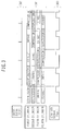
- FIG. 4 An embodiment of the verification device 102 that provides assertion-based verification will now be described with reference to a timing diagram ( Fig. 4 ), a state transition diagram ( Fig. 5 ), and a state transition table ( Fig. 6 ).
- Fig. 4 is a timing diagram illustrating waveforms of the crank signal (REF) 302 and ignition signal (Ign.) 303.
- the intervals of the crank signal (REF) 302 vary with engine speed. More specifically, the interval between one crank signal (REF) and the next is long when the engine speed is low and decreases with an increase in the engine speed.
- the period during which the ignition signal (Ign.) 303 is High is determined according to the electrical energy to be stored in the igniter 207. It is independent of the engine speed.
- the High" period of the ignition signal (Ign.) is between two adjacent crank signals (REF) as indicated by the reference numeral 401 in Fig. 4 .
- the "High" period of the ignition signal (Ign.) ranges crossing the crank signal (REF) as indicated by the reference numeral 402.
- an engine ignition point at which the level of the ignition signal (Ign.) 303 changes from High to Low occurs once and should occur once between the two adjacent crank signals (REF).
- a timing signal for changing the level of the ignition signal (Ign.) 303 from High to Low and a timing signal for changing the level of the ignition signal (Ign.) 303 from Low to High is generated when a general-purpose timer, which is a peripheral device 104, exercises its compare match function.
- the timing signal generated in this manner constitutes a factor for interrupt signal generation. This phenomenon is briefly referred to as an output compare (OC).
- the intervals of the crank signal (REF) 302 are measured by an input capture function of the general-purpose timer for engine-speed measurement purposes. Similarly, this measurement constitutes a factor for interrupt signal generation. This phenomenon is briefly referred to as an input capture (IC).
- State S1 is defined as a state in which the crank signal (REF) 302 has not arrived and the ignition signal (Ign.) 303 is Low.
- State S2 is defined as a state in which the crank signal (REF) 302 has arrived and the ignition signal (Ign.) 303 is Low.
- State S4 is defined as a state in which the crank signal (REF) 302 has not arrived and the ignition signal (Ign.) 303 is High.
- State S3 is defined as a state in which the crank signal (REF) 302 has arrived and the ignition signal (Ign.) 303 is High.
- crank signal (REF) is considered to have not arrived when state S3 arises
- state S1 follows state S3. Ignition occurs at the time when the status changes from state S3 to state S1.
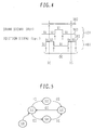
- Fig. 5 is a state transition diagram that illustrates various states while regarding the output compare (OC) and input capture (IC) as events constituting transition conditions.
- Fig. 5 the circled symbols represent states that correspond to the states shown in Fig. 4 . Each state is connected to another state with arrows. The direction of the arrow indicates that of state transition. Alphabetical characters attached to the arrows (IC and OC) indicate a transition condition that serves as a trigger for state transition.
- state S0 is a state in which the verification device 102 is in its initial state, that is, a standby state before the start of assertion-based verification.
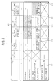
- Fig. 6 is a state transition table that indicates the above-mentioned state transitions.
- the types of various states (601) are indicated in the row direction with the types of transition events (602) indicated in the column direction.
- a state transition that occurs when a particular event is input in a particular state can be determined by viewing the cell at the intersection of the column related to the event and the row related to the state.
- a state transition that occurs when an OC event is input in state S1 can be determined by viewing cell 603.
- the upper row reads "4" while the lower row reads "Start of power application”.
- the number "4" in the upper row indicates that the state is about to change to state S4.
- the lower row generally indicates the process that is to be performed upon state transition.
- the verification device 102 merely estimates an internal state transition of the control software incorporated in the microcomputer 101 (or functional requests for the entire system) and monitors the behavior. Therefore, the meaning of a state transition as the entire system is indicated here.
- a cell marked x indicates an impossible combination of a state and an event. It means that no state transition occurs even if any such event arises. It can be considered that the current state arises again upon state transition.
- the SO column corresponds to state SO, which is shown in Fig. 5 . It means that the step does not proceed so as to the S1 column to start an assertion verification process until the microcomputer issues a software trap instruction ("TR" event (602) in Fig. 6 ).
- TR software trap instruction
- Cell 604 indicates that an IC event occurred during state S2. It means that the level of the ignition signal (Ign.) did not rise from Low to High during a period of the crank signal (REF). It obviously indicates a "misfire" error. When such an abnormal transition is detected, the verification device 102 generates the aforementioned warning signal so that the status changes to state S0 to stop the verification process.
- Ign. the level of the ignition signal
- REF crank signal
- cell 605 indicates that an IC event for the next crank signal (REF) arrived while the ignition signal (Ign.) was High. It implies that a "misfire” error occurred due to delayed ignition timing.
- Cell 606 indicates that ignition occurred again during the time interval between the instant at which ignition was already invoked by the crank signal (REF) and the instant at which the next crank signal (REF) arrives. It implies that an "erroneous ignition" error occurred.
- the verification device 102 traces state transitions and detects an abnormal state when it recognizes a deviation from the normal state transitions shown in Fig. 5 .
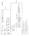
- Fig. 7 shows a place from which a transition condition (event) for the verification device 102 is to be collected.
- interrupt controller 105 All important events that occur within a peripheral device 104 are individually conveyed to the interrupt controller 105 in the form of an interrupt factor 701.
- the interrupt controller 105 is under control of the CPU core 103.
- the reason is that the control software can perform setup through the CPU core 103 to select the interrupt factor to be used and define the priorities of the accepted interrupts.
- interrupt factors 701 are passed through the interrupt controller 105, they are turned into interrupt signals 703 that have been subjected to masking and prioritization processes and sequentially conveyed to the CPU core 103.
- the verification device 102 acquire the information about all interrupt factors without being disturbed by the control software.
- the decision of the priority order is an extra ornamentation for the functions according to the present invention.
- the station transitions of the verification device 102 need to be properly performed in accordance with the order of events.
- the processing time required for such state transitions is negligible when compared to the processing time required for control software execution by the CPU core 103.
- the essential configuration to be formed is such that a raw interrupt factor 701, which is not yet passed through the interrupt controller 105, is branched and acquired as a transition condition (event) 702 for the verification device 102.
- Fig. 8 shows executable software that is obtained by converting the state transition table shown in Fig. 6 .
- the software is written in C language syntax.
- the software is converted to a data string, for instance, by a firmware compiler, and stored in the control storage 113 of the verification device 102.
- Program block 801 is obtained when the state transition table shown in Fig. 6 is rewritten as a two-dimensional structure table. A row in the two-dimensional table is searched for by the prevailing status ("status"), whereas a column is searched for by the type of a transition event ("event").
- An element in the above two-dimensional table is expressed by the combination of a number and a function name.
- the array element " ⁇ 4, nop ⁇ " corresponding to cell 603 in Fig. 6 indicates that the next status to proceed to is state S4, which is designated by the array subscript "4", and that the value of a function pointer for the function to be recalled upon transition to the next status is "nop".
- Program block 802 shows an execution section that actually performs a state transition trace. The flow of execution will be described later with reference to a flowchart in Fig. 9 .
- Program block 803 is a function block that is to be recalled upon normal transition.
- Program block 804 is a function block that is to be recalled upon abnormal transition. The functions of these two blocks will be described in detail later with reference to the flowchart in Fig. 9 .
- Fig. 9 is a flowchart illustrating program blocks 802, 803, and 804, which govern main operations indicated in Fig. 8 .
- a start point 900 is a place where an operation is positioned after the verification device 102 is subjected to a hardware reset. Subsequently, process 901 is performed to initialize the status variable "status". This places the verification device 102 in state S0, which is shown in Fig. 5 .
- an event wait function "WaitEvent()" is used to wait until an external event is generated. It is assumed that the “WaitEvent () " function stands by within itself until an event is generated, and returns an event type as a return value when an event is generated. To clarify this attribute, Fig. 9 shows a loop for returning to the beginning of process 902 until judgment 903 indicates that an event is generated.
- process 904. the current state number and event number are used to search the aforementioned two-dimensional table 801 and acquire the next state number as the variable "nextstatus".
- process 905 is performed.
- the current state number and event number are used again to search the two-dimensional table of program block 801 and acquire the value of a function pointer for the function to be executed as the variable "callp".
- process 906 is performed.
- the above function pointer is used to call an actual function.
- the "nop function" for processes 908 to 910 is called in accordance with the definition formulated by the two-dimensional table of program block 801, as described earlier, and no process is performed in the present embodiment.
- the "err function" for processes 911 to 913 is called.
- means for issuing a warning signal to the outside (warning signal 121 shown in Fig. 1 ) or transmitting a warning interrupt signal to the microcomputer (warning interrupt signal 120 shown in Fig. 1 ) can be used to exercise the "err function".
- process 907 is performed.
- the new state number obtained in process 904 is used to update the status variable "status", which indicates the current status, by rewriting its contents.
- the verification device 102 and microcomputer 101 start to operate in parallel with each other independently of each other's operation, a synchronization process must be performed at the beginning of their operation to ensure that their status recognitions match. Further, since the operation stops (the status returns to state SO) when the verification device 102 detects an abnormality, the synchronization process needs to be performed also to subsequently restart the verification device 102.
- a start point 1000 in Fig. 10 is a point at which the control software for the microcomputer 101 begins to start up. It also represents the place after a hardware reset.
- process 1001 is performed.
- process 1001 an overall engine control initialization process is performed including the ignition control according to the present embodiment. Subsequently, the flow proceeds to judgment 1002.
- Judgment 1002 is formulated to determine whether the entire system is in state S1, which is shown in Figs. 4 and 5 . If the entire system is not in state S1, a standby operation is performed.
- State S1 is a state in which the engine is stopped. It is therefore obvious that state S1 prevails immediately after startup. However, the above judgment is formulated to achieve synchronism with the verification device 102 even in the cases of a certain processing delay or the immediate startup right after the power is turned on.
- process 1003 is performed to transmit a software trap interrupt to the verification device 102.
- This operation places the verification device 102 in state S1 so that the microcomputer 101 and verification device 102 synchronize with each other.
- Fig. 11 is a flowchart illustrating an abnormality warning interrupt processing routine that the microcomputer 101 executes after the verification device 102 detects an abnormal transition and transmits a warning interrupt to the microcomputer 101 as described earlier.
- a nonvolatile storage (not shown) stores snapshots of the engine speed, intake air amount, or other prevailing important variables of the control software as abnormality information together with the current timestamp.
- a warning signal (e.g., lamp illumination) is output to the outside so that the driver can recognize the abnormality.
- the warning signal output is generated by the microcomputer 101 and different from the warning signal 121 shown in Fig. 1 , which is output from the verification device 102. It is, for instance, an output (input/output signal 107 shown in Fig. 1 ) that is generated from a digital output port, which is a peripheral device 104 shown in Fig. 1 .
- Block 1106, which includes subsequent judgment 1103 and process 1104, is the same as block 1005, which includes blocks 1002 and 1003 shown in Fig. 10 .
- This block 1106 performs a synchronization process that is necessary for restarting the verification device 102, which has reported an abnormality and has stopped.
- the verification device 102 can be used as an onboard abnormality monitoring device for embedding in a product to meet the above applications requirements.
Landscapes
- Engineering & Computer Science (AREA)
- Theoretical Computer Science (AREA)
- Quality & Reliability (AREA)
- Physics & Mathematics (AREA)
- General Engineering & Computer Science (AREA)
- General Physics & Mathematics (AREA)
- Debugging And Monitoring (AREA)
- Test And Diagnosis Of Digital Computers (AREA)
Applications Claiming Priority (1)
| Application Number | Priority Date | Filing Date | Title |
|---|---|---|---|
| JP2006340039A JP4496205B2 (ja) | 2006-12-18 | 2006-12-18 | 制御用マイクロコンピュータの検証装置および車載用制御装置 |
Publications (3)
| Publication Number | Publication Date |
|---|---|
| EP1950657A2 true EP1950657A2 (fr) | 2008-07-30 |
| EP1950657A3 EP1950657A3 (fr) | 2008-09-03 |
| EP1950657B1 EP1950657B1 (fr) | 2015-01-07 |
Family
ID=39325615
Family Applications (1)
| Application Number | Title | Priority Date | Filing Date |
|---|---|---|---|
| EP07022948.9A Ceased EP1950657B1 (fr) | 2006-12-18 | 2007-11-27 | Dispositif de vérification d'un ordinateur de commande et dispositif de commande installable sur véhicule |
Country Status (3)
| Country | Link |
|---|---|
| US (1) | US7730354B2 (fr) |
| EP (1) | EP1950657B1 (fr) |
| JP (1) | JP4496205B2 (fr) |
Families Citing this family (10)
| Publication number | Priority date | Publication date | Assignee | Title |
|---|---|---|---|---|
| US7822899B2 (en) | 2007-03-08 | 2010-10-26 | Renesas Electronics Corporation | Data processor and control system |
| US8074118B2 (en) * | 2009-01-28 | 2011-12-06 | Dspace Digital Signal Processing And Control Engineering Gmbh | Method for influencing a control unit and manipulation unit |
| WO2013073009A1 (fr) * | 2011-11-15 | 2013-05-23 | トヨタ自動車株式会社 | Système de microcalculateurs, et microcalculateur de contrôle |
| JP5652434B2 (ja) | 2012-06-15 | 2015-01-14 | 株式会社デンソー | モータ制御装置、及び、これを用いた電動パワーステアリング装置 |
| US9874863B2 (en) * | 2015-08-24 | 2018-01-23 | Keysight Technologies, Inc. | Finite state machine-based trigger event detection employing interpolation |
| JP6629999B2 (ja) * | 2016-04-12 | 2020-01-15 | ガードノックス・サイバー・テクノロジーズ・リミテッドGuardKnox Cyber Technologies Ltd. | セキュアロックダウンを実装するように構成された関連装置を有する特別にプログラムされたコンピューティングシステムおよびその使用方法 |
| EP3466795B1 (fr) * | 2016-05-24 | 2020-08-19 | Mitsubishi Electric Corporation | Dispositif de commande électronique et son procédé de commande de fonctionnement |
| JP6838234B2 (ja) | 2017-03-24 | 2021-03-03 | 日立Astemo株式会社 | 車両制御装置 |
| AT522186B1 (de) * | 2019-05-20 | 2020-09-15 | Dipl Ing Dipl Ing Fh Markus Gruber | Computerimplementiertes Verfahren zur rechnergestützten Erzeugung eines ausführbaren Steuerungsprogramms zur Steuerung und/oder Regelung eines technischen Prozesses |
| WO2022239098A1 (fr) | 2021-05-11 | 2022-11-17 | 三菱電機株式会社 | Dispositif de commande de machine électrique tournante |
Citations (1)
| Publication number | Priority date | Publication date | Assignee | Title |
|---|---|---|---|---|
| JP2006012017A (ja) | 2004-06-29 | 2006-01-12 | Denso Corp | 状態にアクションを割り当てた対応情報に基づいてプログラムを生成するプログラム生成プログラム、プログラム生成装置、およびプログラム生成方法,ならびに、この対応情報の生成プログラム、対応情報生成装置、および対応情報生成方法 |
Family Cites Families (25)
| Publication number | Priority date | Publication date | Assignee | Title |
|---|---|---|---|---|
| JPS61165159A (ja) * | 1984-12-19 | 1986-07-25 | Fujitsu Ltd | 遷移状態チエツク回路 |
| JPS6474637A (en) * | 1987-09-16 | 1989-03-20 | Nec Corp | Debugging control circuit |
| JPH0292535U (fr) * | 1989-01-06 | 1990-07-23 | ||
| US5163016A (en) * | 1990-03-06 | 1992-11-10 | At&T Bell Laboratories | Analytical development and verification of control-intensive systems |
| JPH052654A (ja) * | 1991-06-25 | 1993-01-08 | Nissan Motor Co Ltd | マイクロコンピユータの故障検知方法および回路 |
| JP4317672B2 (ja) * | 2001-06-12 | 2009-08-19 | 三菱重工業株式会社 | Cpu異常監視装置 |
| US20030135842A1 (en) * | 2002-01-16 | 2003-07-17 | Jan-Erik Frey | Software development tool for embedded computer systems |
| US6957368B2 (en) * | 2002-01-23 | 2005-10-18 | Medtronic Emergency Response Systems, Inc. | Hazard mitigation in medical device |
| AU2003240948A1 (en) * | 2002-05-28 | 2003-12-12 | Cadence Design Systems, Inc. | Assertion-based transaction recording |
| JP2004234720A (ja) * | 2003-01-29 | 2004-08-19 | Toshiba Corp | 半導体装置およびその状態遷移チェック方法 |
| US20050204345A1 (en) * | 2004-02-25 | 2005-09-15 | Rivera Jose G. | Method and apparatus for monitoring computer software |
| US7243322B1 (en) * | 2004-06-01 | 2007-07-10 | Tai An Ly | Metastability injector for a circuit description |
| US7278056B2 (en) * | 2004-06-09 | 2007-10-02 | International Business Machines Corporation | Methods, systems, and media for management of functional verification |
| JP2006053788A (ja) * | 2004-08-12 | 2006-02-23 | Ntt Docomo Inc | ソフトウェア動作監視装置及びソフトウェア動作監視方法 |
| JP4647276B2 (ja) * | 2004-09-30 | 2011-03-09 | ルネサスエレクトロニクス株式会社 | 半導体回路装置 |
| US7143373B2 (en) * | 2004-10-14 | 2006-11-28 | Synopsys, Inc. | Method and apparatus for evaluating and debugging assertions |
| JP2006119905A (ja) * | 2004-10-21 | 2006-05-11 | Matsushita Electric Ind Co Ltd | 障害検出装置及びコンピュータシステム |
| US7404160B2 (en) * | 2005-02-18 | 2008-07-22 | Quickturn Design Systems Inc. | Method and system for hardware based reporting of assertion information for emulation and hardware acceleration |
| US7313772B2 (en) * | 2005-05-24 | 2007-12-25 | International Business Machines Corporation | Systems, methods, and media for block-based assertion generation, qualification and analysis |
| JP2006330864A (ja) * | 2005-05-24 | 2006-12-07 | Hitachi Ltd | サーバ計算機システムの制御方法 |
| US7528622B2 (en) * | 2005-07-06 | 2009-05-05 | Optimal Test Ltd. | Methods for slow test time detection of an integrated circuit during parallel testing |
| US7496788B1 (en) * | 2006-08-17 | 2009-02-24 | Nvidia Corporation | Watchdog monitoring for unit status reporting |
| US7548826B2 (en) * | 2006-08-24 | 2009-06-16 | Blue Pillar, Inc. | Power monitoring and testing |
| US8024691B2 (en) * | 2006-09-28 | 2011-09-20 | Mcgill University | Automata unit, a tool for designing checker circuitry and a method of manufacturing hardware circuitry incorporating checker circuitry |
| JP5324792B2 (ja) * | 2008-01-28 | 2013-10-23 | インターナショナル・ビジネス・マシーンズ・コーポレーション | システムの動作を検証するシステムおよび方法 |
-
2006
- 2006-12-18 JP JP2006340039A patent/JP4496205B2/ja not_active Expired - Fee Related
-
2007
- 2007-11-27 EP EP07022948.9A patent/EP1950657B1/fr not_active Ceased
- 2007-12-04 US US11/950,125 patent/US7730354B2/en not_active Expired - Fee Related
Patent Citations (1)
| Publication number | Priority date | Publication date | Assignee | Title |
|---|---|---|---|---|
| JP2006012017A (ja) | 2004-06-29 | 2006-01-12 | Denso Corp | 状態にアクションを割り当てた対応情報に基づいてプログラムを生成するプログラム生成プログラム、プログラム生成装置、およびプログラム生成方法,ならびに、この対応情報の生成プログラム、対応情報生成装置、および対応情報生成方法 |
Also Published As
| Publication number | Publication date |
|---|---|
| EP1950657A3 (fr) | 2008-09-03 |
| JP2008152544A (ja) | 2008-07-03 |
| JP4496205B2 (ja) | 2010-07-07 |
| US20080147949A1 (en) | 2008-06-19 |
| US7730354B2 (en) | 2010-06-01 |
| EP1950657B1 (fr) | 2015-01-07 |
Similar Documents
| Publication | Publication Date | Title |
|---|---|---|
| EP1950657B1 (fr) | Dispositif de vérification d'un ordinateur de commande et dispositif de commande installable sur véhicule | |
| US8868989B2 (en) | System for testing error detection circuits | |
| US4339801A (en) | Automatic control system for method and apparatus for checking devices of an automotive vehicle in use with a microcomputer | |
| USRE31582E (en) | Automatic control system for method and apparatus for checking devices of an automotive vehicle in use with a microcomputer | |
| JP2002202001A (ja) | 自己診断機能を備えた車両用制御装置及び記録媒体 | |
| US4493078A (en) | Method and apparatus for testing a digital computer | |
| JP2009295126A (ja) | シミュレーション方法、システム及びプログラム | |
| JP2010237895A (ja) | 車載電子制御装置,制御ソフトウェアおよび制御ソフトウェアの開発ツール | |
| US7930165B2 (en) | Procedure and device for emulating a programmable unit providing system integrity control | |
| CN106647701A (zh) | 一种航空发动机控制器bit测试方法 | |
| JPWO2010104135A1 (ja) | シミュレーション方法、システム及びプログラム | |
| JPS5968004A (ja) | 車載用コンピユ−タのフエイルセ−フ方法 | |
| CN101802793A (zh) | 处理飞行器机载系统的运行软件在调试阶段期间处理的信息容量的方法和实施该方法的设备 | |
| WO2020221097A1 (fr) | Procédé et dispositif basés sur une machine à états finis pour une modélisation formelle de couche d'exigence de système d'exploitation | |
| EP1095333B1 (fr) | Detection des dysfonctionnements dans un systeme numerique | |
| Boulanger | Requirements engineering in a model-based methodology for embedded automotive software | |
| CN103713977A (zh) | 一种微处理器ip核比较验证的实现方法 | |
| Peraldi-Frati et al. | Scheduling multi clock real time systems: From requirements to implementation | |
| JP2009080566A (ja) | 車両制御用プログラムおよびプログラム生成方法、プログラム生成装置、及び自動車用制御装置 | |
| KR20240112059A (ko) | 결함 주입 테스트 방법 및 장치와 결함 주입 방법 | |
| Resmerita et al. | Verification of embedded control systems by simulation and program execution control | |
| JP2011118637A (ja) | システムテスト仕様生成装置及び試験装置 | |
| JP2010086207A (ja) | シミュレーション方法、システム及びプログラム | |
| Gaglio | Design and realization of an open-loop simulator for ICE control unit, developing the crankshaft and camshaft sensors simulation | |
| MUTHA et al. | Optimized Engine Off Time Estimation for Cold Start Detection in Emission Diagnostics |
Legal Events
| Date | Code | Title | Description |
|---|---|---|---|
| PUAI | Public reference made under article 153(3) epc to a published international application that has entered the european phase |
Free format text: ORIGINAL CODE: 0009012 |
|
| AK | Designated contracting states |
Kind code of ref document: A2 Designated state(s): AT BE BG CH CY CZ DE DK EE ES FI FR GB GR HU IE IS IT LI LT LU LV MC MT NL PL PT RO SE SI SK TR |
|
| AX | Request for extension of the european patent |
Extension state: AL BA HR MK RS |
|
| PUAL | Search report despatched |
Free format text: ORIGINAL CODE: 0009013 |
|
| RIC1 | Information provided on ipc code assigned before grant |
Ipc: G06F 11/07 20060101ALI20080724BHEP Ipc: G06F 11/00 20060101AFI20080619BHEP |
|
| AK | Designated contracting states |
Kind code of ref document: A3 Designated state(s): AT BE BG CH CY CZ DE DK EE ES FI FR GB GR HU IE IS IT LI LT LU LV MC MT NL PL PT RO SE SI SK TR |
|
| AX | Request for extension of the european patent |
Extension state: AL BA HR MK RS |
|
| 17P | Request for examination filed |
Effective date: 20080915 |
|
| 17Q | First examination report despatched |
Effective date: 20081009 |
|
| AKX | Designation fees paid |
Designated state(s): DE FR |
|
| GRAP | Despatch of communication of intention to grant a patent |
Free format text: ORIGINAL CODE: EPIDOSNIGR1 |
|
| INTG | Intention to grant announced |
Effective date: 20140623 |
|
| GRAS | Grant fee paid |
Free format text: ORIGINAL CODE: EPIDOSNIGR3 |
|
| RIN1 | Information on inventor provided before grant (corrected) |
Inventor name: MIYAKE, JUNJI |
|
| GRAA | (expected) grant |
Free format text: ORIGINAL CODE: 0009210 |
|
| AK | Designated contracting states |
Kind code of ref document: B1 Designated state(s): DE FR |
|
| REG | Reference to a national code |
Ref country code: DE Ref legal event code: R096 Ref document number: 602007039931 Country of ref document: DE Effective date: 20150226 |
|
| REG | Reference to a national code |
Ref country code: DE Ref legal event code: R097 Ref document number: 602007039931 Country of ref document: DE |
|
| PLBE | No opposition filed within time limit |
Free format text: ORIGINAL CODE: 0009261 |
|
| STAA | Information on the status of an ep patent application or granted ep patent |
Free format text: STATUS: NO OPPOSITION FILED WITHIN TIME LIMIT |
|
| REG | Reference to a national code |
Ref country code: FR Ref legal event code: PLFP Year of fee payment: 9 |
|
| 26N | No opposition filed |
Effective date: 20151008 |
|
| REG | Reference to a national code |
Ref country code: FR Ref legal event code: PLFP Year of fee payment: 10 |
|
| REG | Reference to a national code |
Ref country code: FR Ref legal event code: PLFP Year of fee payment: 11 |
|
| PGFP | Annual fee paid to national office [announced via postgrant information from national office to epo] |
Ref country code: DE Payment date: 20171121 Year of fee payment: 11 Ref country code: FR Payment date: 20171012 Year of fee payment: 11 |
|
| REG | Reference to a national code |
Ref country code: DE Ref legal event code: R119 Ref document number: 602007039931 Country of ref document: DE |
|
| PG25 | Lapsed in a contracting state [announced via postgrant information from national office to epo] |
Ref country code: FR Free format text: LAPSE BECAUSE OF NON-PAYMENT OF DUE FEES Effective date: 20181130 Ref country code: DE Free format text: LAPSE BECAUSE OF NON-PAYMENT OF DUE FEES Effective date: 20190601 |