EP1950829A1 - Antenne parabolique portable - Google Patents
Antenne parabolique portable Download PDFInfo
- Publication number
- EP1950829A1 EP1950829A1 EP08150596A EP08150596A EP1950829A1 EP 1950829 A1 EP1950829 A1 EP 1950829A1 EP 08150596 A EP08150596 A EP 08150596A EP 08150596 A EP08150596 A EP 08150596A EP 1950829 A1 EP1950829 A1 EP 1950829A1
- Authority
- EP
- European Patent Office
- Prior art keywords
- satellite dish
- dish
- support
- portable
- legs
- Prior art date
- Legal status (The legal status is an assumption and is not a legal conclusion. Google has not performed a legal analysis and makes no representation as to the accuracy of the status listed.)
- Withdrawn
Links
- 238000005259 measurement Methods 0.000 claims description 5
- 230000001419 dependent effect Effects 0.000 description 1
- 230000005611 electricity Effects 0.000 description 1
- 230000005484 gravity Effects 0.000 description 1
- 238000000034 method Methods 0.000 description 1
- 230000003068 static effect Effects 0.000 description 1
Images
Classifications
-
- H—ELECTRICITY
- H01—ELECTRIC ELEMENTS
- H01Q—ANTENNAS, i.e. RADIO AERIALS
- H01Q1/00—Details of, or arrangements associated with, antennas
- H01Q1/12—Supports; Mounting means
- H01Q1/1235—Collapsible supports; Means for erecting a rigid antenna
-
- H—ELECTRICITY
- H01—ELECTRIC ELEMENTS
- H01Q—ANTENNAS, i.e. RADIO AERIALS
- H01Q1/00—Details of, or arrangements associated with, antennas
- H01Q1/12—Supports; Mounting means
- H01Q1/125—Means for positioning
-
- H—ELECTRICITY
- H01—ELECTRIC ELEMENTS
- H01Q—ANTENNAS, i.e. RADIO AERIALS
- H01Q3/00—Arrangements for changing or varying the orientation or the shape of the directional pattern of the waves radiated from an antenna or antenna system
- H01Q3/02—Arrangements for changing or varying the orientation or the shape of the directional pattern of the waves radiated from an antenna or antenna system using mechanical movement of antenna or antenna system as a whole
Definitions
- This invention relates to a portable and adjustable satellite dish. More specifically but not exclusively this invention relates to a portable and adjustable satellite dish which is manually adjustable.
- a portable system is required to be regularly reset and adjusted according to the position of it and its location in the world. This can be particularly problematic since the surface upon which the dish is mounted may be uneven and cause the dish to be unstable.
- a satellite dish be transported by recreational vehicles for use on site and then set by the user.
- Elevation refers to the angle between the satellite, and the local horizontal plane. It is the up-down angle.
- Most domestic satellite dishes have an offset angle of elevation, this varies according to the dish manufacturer but typically offset angles are approximately 22° to 28°.
- a dish with an offset angle of around 26° would need to be pointed at 64° from the vertical.
- Most dishes are provided with a back bracket showing pre-marked elevation degrees. These take into account the offset angle of the satellite dish but are only treated as an approximate guide as they rely on the pole (to which the dish is mounted) being truly vertical. In other European locations the elevation angle is normally between the range of 15° to 41°.
- This elevation angle may be set using an inclinometer. These typically have a rotary scale marked in degrees and the dish is pivoted to the predetermined degree angle. However it is sometimes difficult to accurately set this angle as the offset angle of the dish is unknown.
- Azimuth refers to the rotation of the whole antenna around a vertical axis. It is the side to side angle. Typically you loosen the main mount bracket and swing the whole dish all the way round in a 360° circle. By definition North is 0°, East is 90°, South is 180° and West is 270°. North can also be called 360°.
- a satellite may be found by presetting the elevation accurately and then swinging the whole antennae boldly in an azimuth until the signal blocks up so in present systems an approximate azimuth angle can sometimes work.
- a portable satellite dish comprising at least one foldable support pivotably attached to the satellite dish and movable from a stowed position in which it lies adjacent to the satellite dish to an open and in use position where it supplies one support for the dish, part of the circumference edge of the dish itself supplying the second support.
- the support mount comprises two legs such that the satellite dish has three points of contact and support, one being provided by itself.
- the support bracket is provided with angle setting measurements.
- the satellite dish comprises a spirit level to enable the amgle of elevation to be set accurately and straightforwardly.
- the satellite dish comprises a receiver and a parabola reflector and is pivotably movable to a pre-determined position.
- the receiver is attached to the highest vertical point of the circumference of the parabolic reflector.
- a portable satellite dish and satellite dish mounting apparatus comprising at least two legs pivotally connected such that each leg is movable with respect to one another, one leg being arranged to support said satellite dish wherein the movement of said legs with respect to one another allows the satellite dish to be positioned to a predetermined angle of elevation.
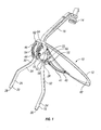
- a satellite dish 10 is shown in an extended and in use position of Figures 1 and 2 and comprises a parabolic reflective 12 and a receiver 14 connected to the reflector via a mounting (16).
- a suitable cable (not shown) connects to a satellite receiver normally powered by the mains electricity supply, the receiver is attached to a television set.
- a pair of legs 18 and 20 are pivotably connected to the parabolic reflector.
- the legs 18 and 20 comprise outer parallel sections 24 and 26 extending to inner parallel sections 28 and 30 via angle portions 32 and 34.
- the base outer parallel sections 24 and 26 of each leg have a rubber support 36 and 38 which prevents slippage once in position.
- a parabolic reflector 12 comprises a lower bracket 40 attached by a suitable fixing mechanism (not shown) to the convex underside 42 of the parabolic reflector 12.
- Two upper support brackets 44 and 46 are attached to the lower support bracket via fixing screws.
- Each support bracket 44 and 46 is substantially semicircular and includes an arcuate slot 52 and 54.
- the legs 18 and 20 are each pivotally connected to the upper and lower support brackets 44, 46 and 40 via a horizontal pivot pin 55.
- a further fixing screw 56 is also connected to the inner parallel leg sections 28 and 30 via two pairs of washers 58 and 60 and via the arcuate slots 52 and 54 (the second set of washers are hidden from view) and is positioned just underneath the pivot pin 55.
- the angle position of the legs 18 and 20 are adjustable by rotation about the pivot pin 55 and then fixed in the desired position by manually tightening the fixing mechanism 56.
- Suitable graduation or indicia 62 are provided on one or each of the upper support brackets 48 and 50 along the arcuate slots 52 and 54. These measurements allow the satellite dish to be pivotably moved with respect to the legs so that the elevation of the satellite dish is at a predetermined angle.
- An indicator pin 70 allows accurate positioning of the satellite dish 10.
- a spirit level 64 is mounted on the upper support bracket 44.
- the user determines the correct elevation angle required for their location.
- the inclinometer is set to the required elevation. That is to say that the indicator 70 is at the required angle noted by the indicia 62.
- the legs 18 and 20 are pulled back until the spirit level bubble is level. The legs 18 and 20 are only pulled back as required and not normally extended fully.
- the combination of the spirit level device and the adjustable leg angle provides an accurate elevation reading once the elevation angle has been preset to the required elevation and the spirit bubble is level. It is also proposed to optionally supply a further spirit level located on the dish arm 16 This would enable a minor adjustment of the legs to be made whilst ensuring that the arm of the dish holding the reflector is in a horizontal plane and that the dish is not unduly tilted. This would provide a very accurate elevation.
- This proposed second spirit level is not shown in the present drawings.
- the legs 18 and 20 are opened out from their folded stow position by undoing the fixing screws 56. Once unfolded a suitable reasonably flat surface is found to position the system. This positioning is assisted by ensuring the spirit level bubble remains substantially central.
- a suitable level surface is found and the legs are opened and the dish 10 is moved to a predetermined bearing (azimuth).
- a predetermined bearing azimuth
- the azimuth and elevation details are provided separately and are dependent on the geographic location of the user.
- the strip is placed in the correct position the dish is mounted over it and aligned thereto.
- the rim of the parabolic dish 12 provides a third support point, the other two support points being provided by the legs 18 and 20.
- Adjustment of the elevation of the satellite dish is provided by pivoting it until the indicator 70 is at the predetermined angle or measurement of provided by the indicia 62. Once at this predetermined position, the fixing device 55 is tightened.
- This satellite dish is particularly advantageous as it negates the need for a tripod support which is bulky and can be unstable. It allows the centre of gravity of the system to be lowered which inherently improves stability. The legs 18 and 20 are also able to be stowed away neatly under the dish 12.
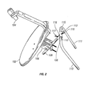
- a parabolic reflector 102 is connected to a receiver 104 and further comprises a mounting bracket 106.
- the mounting bracket 106 is slideably mounted on a first support leg 108.
- This first support leg is pivotally connected to two angled legs 110 and 111. Pivotal movement of said first support leg 108 with respect to said legs 110 and 111 is facilitated by a hollow T-shaped receiver 112.
- This hollow T-shaped receiver 112 comprises a T bar end 114, the T bar receives the end 113 and 115 of the legs 110 and 111.
- the connection is secured via a fixing screw 116.
- a further fixing screw 117 fixes the hollow support bar 108 into the T-section 118 of the T bar 114.
Landscapes
- Aerials With Secondary Devices (AREA)
- Support Of Aerials (AREA)
Applications Claiming Priority (1)
| Application Number | Priority Date | Filing Date | Title |
|---|---|---|---|
| GBGB0701335.2A GB0701335D0 (en) | 2007-01-24 | 2007-01-24 | Portable satellite dish |
Publications (1)
| Publication Number | Publication Date |
|---|---|
| EP1950829A1 true EP1950829A1 (fr) | 2008-07-30 |
Family
ID=37872688
Family Applications (1)
| Application Number | Title | Priority Date | Filing Date |
|---|---|---|---|
| EP08150596A Withdrawn EP1950829A1 (fr) | 2007-01-24 | 2008-01-24 | Antenne parabolique portable |
Country Status (2)
| Country | Link |
|---|---|
| EP (1) | EP1950829A1 (fr) |
| GB (2) | GB0701335D0 (fr) |
Cited By (1)
| Publication number | Priority date | Publication date | Assignee | Title |
|---|---|---|---|---|
| CN104199055A (zh) * | 2014-08-29 | 2014-12-10 | 广州中海达卫星导航技术股份有限公司 | Gnss接收机的电子气泡校验方法及装置 |
Families Citing this family (1)
| Publication number | Priority date | Publication date | Assignee | Title |
|---|---|---|---|---|
| GB2452925B (en) * | 2007-09-19 | 2012-07-25 | Mansar Ltd | Portable satellite dish apparatus and support |
Citations (6)
| Publication number | Priority date | Publication date | Assignee | Title |
|---|---|---|---|---|
| JPS60260208A (ja) * | 1984-06-06 | 1985-12-23 | Matsushita Electric Ind Co Ltd | 車載アンテナ装置 |
| EP0293877A2 (fr) * | 1987-06-03 | 1988-12-07 | Kabushiki Kaisha Toshiba | Antenne parabolique portative |
| GB2208189A (en) * | 1987-07-07 | 1989-03-08 | Toshiba Kk | Portable antenna apparatus for satellite communication |
| EP0683540A1 (fr) * | 1994-05-20 | 1995-11-22 | de los Angeles Gmür-Mosquera, Maria | Antenne pour communication d'un satellite |
| US20020005816A1 (en) * | 2000-07-17 | 2002-01-17 | Carroll Ginther | Satellite dish antenna alignment device |
| CA2494009A1 (fr) * | 2001-05-30 | 2002-12-05 | John R. Essig, Jr | Dispositif reflecteur parabolique gonflable multifonction et procede de fabrication |
Family Cites Families (5)
| Publication number | Priority date | Publication date | Assignee | Title |
|---|---|---|---|---|
| US4656486A (en) * | 1985-07-12 | 1987-04-07 | Turner Allan L | Satellite TV dish antenna support |
| JPH02261202A (ja) * | 1989-03-31 | 1990-10-24 | Toshiba Corp | 可搬式アンテナ装置 |
| FR2649539B1 (fr) * | 1989-07-06 | 1991-11-08 | Yves Devillers | Antenne demontable et aerotransportable pour telecommunications bidirectionnelles avec un satellite |
| US5334990A (en) * | 1990-03-26 | 1994-08-02 | K-Star International Corp. | Ku-band satellite dish antenna |
| GB2432054B (en) * | 2005-11-01 | 2009-10-07 | John Cyril Watkin | Portable offset satellite antenna system |
-
2007
- 2007-01-24 GB GBGB0701335.2A patent/GB0701335D0/en not_active Ceased
-
2008
- 2008-01-24 GB GB0801266A patent/GB2446058A/en not_active Withdrawn
- 2008-01-24 EP EP08150596A patent/EP1950829A1/fr not_active Withdrawn
Patent Citations (6)
| Publication number | Priority date | Publication date | Assignee | Title |
|---|---|---|---|---|
| JPS60260208A (ja) * | 1984-06-06 | 1985-12-23 | Matsushita Electric Ind Co Ltd | 車載アンテナ装置 |
| EP0293877A2 (fr) * | 1987-06-03 | 1988-12-07 | Kabushiki Kaisha Toshiba | Antenne parabolique portative |
| GB2208189A (en) * | 1987-07-07 | 1989-03-08 | Toshiba Kk | Portable antenna apparatus for satellite communication |
| EP0683540A1 (fr) * | 1994-05-20 | 1995-11-22 | de los Angeles Gmür-Mosquera, Maria | Antenne pour communication d'un satellite |
| US20020005816A1 (en) * | 2000-07-17 | 2002-01-17 | Carroll Ginther | Satellite dish antenna alignment device |
| CA2494009A1 (fr) * | 2001-05-30 | 2002-12-05 | John R. Essig, Jr | Dispositif reflecteur parabolique gonflable multifonction et procede de fabrication |
Cited By (1)
| Publication number | Priority date | Publication date | Assignee | Title |
|---|---|---|---|---|
| CN104199055A (zh) * | 2014-08-29 | 2014-12-10 | 广州中海达卫星导航技术股份有限公司 | Gnss接收机的电子气泡校验方法及装置 |
Also Published As
| Publication number | Publication date |
|---|---|
| GB2446058A (en) | 2008-07-30 |
| GB0701335D0 (en) | 2007-03-07 |
| GB0801266D0 (en) | 2008-02-27 |
Similar Documents
| Publication | Publication Date | Title |
|---|---|---|
| US6366253B1 (en) | Satellite antenna alignment device | |
| US5870059A (en) | Antenna mast with level indicating means | |
| US5977922A (en) | Satellite antenna alignment device | |
| US5526010A (en) | Support device for portable satellite dish | |
| US11092667B2 (en) | Portable apparatus for vehicle sensor calibration | |
| US7557764B2 (en) | Means for mounting a portable satellite antenna on a vehicle | |
| US5929817A (en) | Antenna mounts | |
| KR101164411B1 (ko) | 주향 및 경사 측정 장치 및 주향 및 경사 측정 보조 장치 | |
| US20010046258A1 (en) | Portable, self-contained satellite transceiver | |
| US7737900B1 (en) | Mobile satellite dish antenna stand | |
| US6487783B1 (en) | Laser guided chalk line apparatus | |
| TW200909268A (en) | Apparatus and method for wheel alignment | |
| CN111007467B (zh) | 一种无源二面角外定标器 | |
| GB2446058A (en) | Portable satellite dish and its mounting arrangement | |
| US5701679A (en) | Prism support | |
| CN202041207U (zh) | 一种激光水平仪连接器 | |
| US2873531A (en) | Chaining device for surveyors | |
| US7095378B1 (en) | Satellite dish sighting apparatus and alignment system | |
| CN115126974A (zh) | 一种智能检测桥梁墩柱竖直度用测量装置 | |
| CN209142043U (zh) | 一种无线超长待机车载定位防盗设备 | |
| GB2452925A (en) | Portable satellite dish apparatus and support | |
| KR102001924B1 (ko) | 측지측량 기기의 높이조절장치 | |
| JPH06281461A (ja) | 光波距離計用プリズム支持装置 | |
| JPS646572Y2 (fr) | ||
| CN218032437U (zh) | 一种便于调节的全站仪支架 |
Legal Events
| Date | Code | Title | Description |
|---|---|---|---|
| PUAI | Public reference made under article 153(3) epc to a published international application that has entered the european phase |
Free format text: ORIGINAL CODE: 0009012 |
|
| AK | Designated contracting states |
Kind code of ref document: A1 Designated state(s): AT BE BG CH CY CZ DE DK EE ES FI FR GB GR HR HU IE IS IT LI LT LU LV MC MT NL NO PL PT RO SE SI SK TR |
|
| AX | Request for extension of the european patent |
Extension state: AL BA MK RS |
|
| 17P | Request for examination filed |
Effective date: 20090130 |
|
| 17Q | First examination report despatched |
Effective date: 20090306 |
|
| AKX | Designation fees paid |
Designated state(s): AT BE BG CH CY CZ DE DK EE ES FI FR GB GR HR HU IE IS IT LI LT LU LV MC MT NL NO PL PT RO SE SI SK TR |
|
| STAA | Information on the status of an ep patent application or granted ep patent |
Free format text: STATUS: THE APPLICATION IS DEEMED TO BE WITHDRAWN |
|
| 18D | Application deemed to be withdrawn |
Effective date: 20090717 |