EP1950863A2 - Dispositif d'alimentation électrique - Google Patents
Dispositif d'alimentation électrique Download PDFInfo
- Publication number
- EP1950863A2 EP1950863A2 EP08100950A EP08100950A EP1950863A2 EP 1950863 A2 EP1950863 A2 EP 1950863A2 EP 08100950 A EP08100950 A EP 08100950A EP 08100950 A EP08100950 A EP 08100950A EP 1950863 A2 EP1950863 A2 EP 1950863A2
- Authority
- EP
- European Patent Office
- Prior art keywords
- container
- supply unit
- supply
- interior
- electricity
- Prior art date
- Legal status (The legal status is an assumption and is not a legal conclusion. Google has not performed a legal analysis and makes no representation as to the accuracy of the status listed.)
- Withdrawn
Links
Images

Classifications
-
- H—ELECTRICITY
- H01—ELECTRIC ELEMENTS
- H01R—ELECTRICALLY-CONDUCTIVE CONNECTIONS; STRUCTURAL ASSOCIATIONS OF A PLURALITY OF MUTUALLY-INSULATED ELECTRICAL CONNECTING ELEMENTS; COUPLING DEVICES; CURRENT COLLECTORS
- H01R13/00—Details of coupling devices of the kinds covered by groups H01R12/70 or H01R24/00 - H01R33/00
- H01R13/46—Bases; Cases
- H01R13/52—Dustproof, splashproof, drip-proof, waterproof, or flameproof cases
-
- H—ELECTRICITY
- H02—GENERATION; CONVERSION OR DISTRIBUTION OF ELECTRIC POWER
- H02J—ELECTRIC POWER NETWORKS; CIRCUIT ARRANGEMENTS OR SYSTEMS FOR SUPPLYING OR DISTRIBUTING ELECTRIC POWER; SYSTEMS FOR STORING ELECTRIC ENERGY
- H02J7/00—Circuit arrangements for charging or discharging batteries or for supplying loads from batteries
- H02J7/70—Circuit arrangements for charging or discharging batteries or for supplying loads from batteries characterised by the mechanical construction
-
- H—ELECTRICITY
- H01—ELECTRIC ELEMENTS
- H01R—ELECTRICALLY-CONDUCTIVE CONNECTIONS; STRUCTURAL ASSOCIATIONS OF A PLURALITY OF MUTUALLY-INSULATED ELECTRICAL CONNECTING ELEMENTS; COUPLING DEVICES; CURRENT COLLECTORS
- H01R13/00—Details of coupling devices of the kinds covered by groups H01R12/70 or H01R24/00 - H01R33/00
- H01R13/66—Structural association with built-in electrical component
- H01R13/70—Structural association with built-in electrical component with built-in switch
- H01R13/701—Structural association with built-in electrical component with built-in switch the switch being actuated by an accessory, e.g. cover, locking member
-
- H—ELECTRICITY
- H02—GENERATION; CONVERSION OR DISTRIBUTION OF ELECTRIC POWER
- H02J—ELECTRIC POWER NETWORKS; CIRCUIT ARRANGEMENTS OR SYSTEMS FOR SUPPLYING OR DISTRIBUTING ELECTRIC POWER; SYSTEMS FOR STORING ELECTRIC ENERGY
- H02J7/00—Circuit arrangements for charging or discharging batteries or for supplying loads from batteries
- H02J7/50—Circuit arrangements for charging or discharging batteries or for supplying loads from batteries acting upon multiple batteries simultaneously or sequentially
-
- H—ELECTRICITY
- H02—GENERATION; CONVERSION OR DISTRIBUTION OF ELECTRIC POWER
- H02J—ELECTRIC POWER NETWORKS; CIRCUIT ARRANGEMENTS OR SYSTEMS FOR SUPPLYING OR DISTRIBUTING ELECTRIC POWER; SYSTEMS FOR STORING ELECTRIC ENERGY
- H02J7/00—Circuit arrangements for charging or discharging batteries or for supplying loads from batteries
- H02J7/70—Circuit arrangements for charging or discharging batteries or for supplying loads from batteries characterised by the mechanical construction
- H02J7/731—Circuit arrangements for charging or discharging batteries or for supplying loads from batteries characterised by the mechanical construction specially adapted for holding portable devices containing batteries
-
- H—ELECTRICITY
- H02—GENERATION; CONVERSION OR DISTRIBUTION OF ELECTRIC POWER
- H02J—ELECTRIC POWER NETWORKS; CIRCUIT ARRANGEMENTS OR SYSTEMS FOR SUPPLYING OR DISTRIBUTING ELECTRIC POWER; SYSTEMS FOR STORING ELECTRIC ENERGY
- H02J7/00—Circuit arrangements for charging or discharging batteries or for supplying loads from batteries
- H02J7/70—Circuit arrangements for charging or discharging batteries or for supplying loads from batteries characterised by the mechanical construction
- H02J7/751—Circuit arrangements for charging or discharging batteries or for supplying loads from batteries characterised by the mechanical construction concerning the insertion or the connection of the batteries
-
- H—ELECTRICITY
- H02—GENERATION; CONVERSION OR DISTRIBUTION OF ELECTRIC POWER
- H02J—ELECTRIC POWER NETWORKS; CIRCUIT ARRANGEMENTS OR SYSTEMS FOR SUPPLYING OR DISTRIBUTING ELECTRIC POWER; SYSTEMS FOR STORING ELECTRIC ENERGY
- H02J2105/00—Networks for supplying or distributing electric power characterised by their spatial reach or by the load
- H02J2105/40—Networks for supplying or distributing electric power characterised by their spatial reach or by the load characterised by the loads connecting to the networks or being supplied by the networks
- H02J2105/44—Portable electronic devices
Definitions
- This invention relates to an electrical supply unit, and in particular concerns an electrical supply unit which may safely be used to charge battery powered tools in a construction or other work site environment.
- mains voltage in the United Kingdom is 240V, but site voltage is only 110V.
- an electrical supply unit comprising: a sealable container having an interior and being moveable between an open state, in which the interior may be accessed by a user and a closed state, in which the interior may not be accessed by a user; and one or more charging points located in the interior of the container, the or each charging point being operable to provide a first supply of electricity when the container is in the closed position and operable to provide a second supply of electricity when the container is in the open position.
- the second supply of electricity is at a lower voltage than the first supply of electricity.
- the second supply of electricity is zero.
- the electrical supply unit further comprises a detection arrangement to detect whether the container is in the open position or in the closed position.
- the container comprises a closure which is moveable between a first configuration, in which the container is in the open position, and a second configuration, in which the container is in the closed position, and in which first and second contacts are respectively provided on the closure and on a further part of the container, the contacts coming into contact with one another when the closure is in the second configuration but not contacting one another when the closure is in the first configuration.
- the container is lockable in the closed position.
- the first supply of electricity may only be provided when the container is in the locked position.
- the container is of sufficient size to accommodate a power tool or battery pack thereof for each of the charging points within the interior of the container when the interior is in the closed position.
- Another embodiment of the present invention provides an electrical supply unit having an input connector adapted to receive a first, lower voltage; a transformer adapted to convert the incoming supply to a second, higher voltage; and a power distribution unit, adapted to supply the second, higher voltage to one or more electrical devices.
- the supply unit 1 comprises a container having a base 2, four side walls 3 (only two of which are shown in Figure 1 ) and a lid 4, which is hingedly attached to an upper edge of one of the side walls 3.
- the side walls 3 present an upper opening which may be entirely sealed by the lid 4 so that the interior of the unit 1 may be completely isolated from the surroundings thereof.
- a power cable 7 provides power to the unit 1, preferably from a mains source. In the example of current UK building regulations, power supplied to the unit 1 through the cable 7 will be at 110V (site voltage).
- the unit 1 is shown in a closed position, in which the lid 4 has been closed to seal the interior of the unit 1 from its surroundings.
- First and second electrical contacts 8,9 are respectively provided on the lid 4 and on an upper edge of one of the side walls 3, arranged so that, when the lid 4 is in the closed position, the contacts 8 and 9 touch one another and complete a circuit, thus indicating that the lid 4 is in the closed position.
- several sets of contacts may be provided at various locations around the perimeter of the lid 4, to increase the reliability of the unit 1 in determining whether the lid 4 is in the closed or open position.
- any alternative method of detecting the position of the lid 4 may be used, for instance pressure switches, inductance coils or optical sensors may be used.
- a lock 10 may be provided to place the container in a locked position.
- a sensor 18 may also be provided to sense whether the container is locked.
- An example of the sensor 18 is shown inside the unit 1 in figure 2 ; of course, it will be appreciated that the sensor 18 can be located in various different positions and may be attached to the lid 4, a wall 3, and/or the base 2.
- the lid 4 may be opened and a number of rechargeable power tools or battery packs for power tools may be connected to the power points 6, with the tools themselves being placed inside the container.
- the lid 4 When the lid 4 is in the open position, however, no electricity is supplied to the power points 6, and thus at this stage the building regulations which prohibit the supply of mains voltage on site are not violated.
- mains voltage may be supplied to the power points 6, thus allowing the power tools or batteries to be charged effectively.
- mains voltage may only be supplied to the power points 6 if it is determined that the unit 1 is locked.
- the power supply to the unit 1 may be at site voltage, which in the United Kingdom may be 110V.
- one or more transformers 19 are provided in the base 2 of the unit 1, which allow conversion of this input site voltage into mains voltage to be supplied to the power points 6.
- the supply of mains voltage to the power points 6 is immediately ceased.
- This may be achieved by, for example, the use of a relay or other control device 17 which switches off (or otherwise controls) the supply of mains voltage to the power points 6 when the detected position of the lid 4 indicates that the lid 4 is open.
- the relay or other sensing device 17 may also detect signals from the sensor 18 and use this information to switch off or otherwise control the supply of mains voltage to the power points 6.
- mains voltage may only be provided to the power point 6 if the unit 1 is in the locked position.
- a light 11 or other indicator may be provided to show that a mains voltage is being provided to the power points 6, and hence that power tools or batteries connected to the power points 6 will be charging.
- the invention is not limited to this and other parameters, for instance the power or current of the electricity supply, may be varied (eg. through the use of the relay or control device 17).
- embodiments of the present invention provide an electrical supply unit which will find utility in many building site or other work site environments, and which may safely allow the charging of power tools and/or battery packs therefor while remaining within prevailing building regulations.
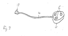
- An electrical connector 12 comprises a plug 13 or other input connector, which is adapted to be connected to an on-site low-voltage supply.
- a cable 14 connects the plug 13 to a power distribution unit 15, which includes a transformer (not shown) to convert the input voltage to a higher voltage.
- the plug 13 is adapted to be connected to a 110 volt "site" voltage, and the transformer is adapted to convert this incoming supply to distribute a "mains" supply at 240 volts.
- One or more power outlets 16 are provided on a face of the power distribution unit 15.
- the cable 14 comprises a retractable extension cable, having a variable length, with any excess cable being retained inside the plug 13 or the power distribution unit 15. This will increase the utility of the connector 12, whilst ensuring that stray lengths of cable are kept to a minimum.
- the connector 12 is provided with one or more circuit breakers (not shown) to protect against potentially damaging overloads.
- the alternative electrical connector will allow power tools to be charged, and low-power tools to be operated, on-site using the available power supply.
Landscapes
- Engineering & Computer Science (AREA)
- Power Engineering (AREA)
- Charge And Discharge Circuits For Batteries Or The Like (AREA)
- Details Of Connecting Devices For Male And Female Coupling (AREA)
Applications Claiming Priority (1)
| Application Number | Priority Date | Filing Date | Title |
|---|---|---|---|
| GB0701446A GB2446013B (en) | 2007-01-25 | 2007-01-25 | An electrical supply unit |
Publications (2)
| Publication Number | Publication Date |
|---|---|
| EP1950863A2 true EP1950863A2 (fr) | 2008-07-30 |
| EP1950863A3 EP1950863A3 (fr) | 2010-02-10 |
Family
ID=37872779
Family Applications (1)
| Application Number | Title | Priority Date | Filing Date |
|---|---|---|---|
| EP08100950A Withdrawn EP1950863A3 (fr) | 2007-01-25 | 2008-01-25 | Dispositif d'alimentation électrique |
Country Status (3)
| Country | Link |
|---|---|
| US (1) | US7589957B2 (fr) |
| EP (1) | EP1950863A3 (fr) |
| GB (1) | GB2446013B (fr) |
Cited By (2)
| Publication number | Priority date | Publication date | Assignee | Title |
|---|---|---|---|---|
| GB2526299A (en) * | 2014-05-19 | 2015-11-25 | Patrick Usher | Construction site charging unit |
| GB2544068A (en) * | 2015-11-04 | 2017-05-10 | Capuzza Rossano | Improvements for an electrical supply unit |
Families Citing this family (3)
| Publication number | Priority date | Publication date | Assignee | Title |
|---|---|---|---|---|
| TWI383290B (zh) * | 2008-06-06 | 2013-01-21 | Asustek Comp Inc | 電纜盒以及應用此電纜盒之個人電腦 |
| GB2512817A (en) | 2013-02-22 | 2014-10-15 | Chargebox Ltd | Secure device charging |
| US9815663B2 (en) * | 2013-11-12 | 2017-11-14 | Zahid Hussain | Electrical wire organization device |
Family Cites Families (17)
| Publication number | Priority date | Publication date | Assignee | Title |
|---|---|---|---|---|
| US5318356A (en) * | 1992-09-22 | 1994-06-07 | Shelton J Calvin | Charger/shelter apparatus for electric shaver |
| US5339956A (en) * | 1993-06-28 | 1994-08-23 | Raymon Thomason | Tool box with combined elements |
| JPH10271700A (ja) * | 1997-03-21 | 1998-10-09 | Sanyo Electric Co Ltd | 充電装置 |
| FR2766950B1 (fr) * | 1997-07-30 | 1999-09-10 | Herve Borgoltz | Dispositif de livraison d'energie electrique |
| GB9722890D0 (en) * | 1997-10-31 | 1998-01-07 | Brook Chrispin Kenneth | Battery charging rack |
| IT1305609B1 (it) * | 1998-04-30 | 2001-05-09 | P M G S N C Dei Flii Paganini | Stazione per la ricarica delle batterie al nichel-cadmio ,alnichel-metal hydride e d'altro tipo,usate negli utensili elettrici |
| US5932939A (en) * | 1998-07-22 | 1999-08-03 | Jeffrey S. Houk | Electrical service disconnect boxes for conveying power to adjacent electrical appliances such as air conditioners |
| US6208507B1 (en) * | 1999-10-08 | 2001-03-27 | Stephen Harvey | Carrying case having plug-in connector and switch modules for a compact portable computer workstation |
| US6633479B2 (en) * | 1999-12-13 | 2003-10-14 | Robert Karl Benson, Inc. | Portable, temporary power hookup for use at construction sites, systems including the same, and methods |
| US6227890B1 (en) * | 2000-02-25 | 2001-05-08 | Antec Corporation | Service entrance unit with generator interface |
| US6326766B1 (en) * | 2000-06-09 | 2001-12-04 | Shoot The Moon Products Ii, Llc | Rechargable battery pack and battery pack charger with safety mechanisms |
| EP1451921A4 (fr) * | 2001-11-02 | 2006-01-11 | Aker Wade Power Technologies L | Chargeur rapide pour batteries haute capacite |
| US7038126B2 (en) * | 2002-06-25 | 2006-05-02 | Jo Solet | Cable/wire and electronic device storage container |
| WO2006021842A1 (fr) * | 2004-07-23 | 2006-03-02 | Gpe International Limited | Chargeurs de batteries |
| US7324332B1 (en) * | 2004-09-07 | 2008-01-29 | Brent Shelton | Electrical enclosure |
| US7417850B1 (en) * | 2006-09-11 | 2008-08-26 | Juan Pulido | Self contained power and signal distribution system for computers and the like |
| US7513361B1 (en) * | 2007-03-16 | 2009-04-07 | Mills Jr James | Powered grooming unit |
-
2007
- 2007-01-25 GB GB0701446A patent/GB2446013B/en not_active Expired - Fee Related
-
2008
- 2008-01-25 US US12/020,440 patent/US7589957B2/en not_active Expired - Fee Related
- 2008-01-25 EP EP08100950A patent/EP1950863A3/fr not_active Withdrawn
Cited By (4)
| Publication number | Priority date | Publication date | Assignee | Title |
|---|---|---|---|---|
| GB2526299A (en) * | 2014-05-19 | 2015-11-25 | Patrick Usher | Construction site charging unit |
| GB2526299B (en) * | 2014-05-19 | 2019-04-10 | Usher Patrick | Construction site charging unit |
| GB2544068A (en) * | 2015-11-04 | 2017-05-10 | Capuzza Rossano | Improvements for an electrical supply unit |
| GB2544068B (en) * | 2015-11-04 | 2021-10-06 | Capuzza Rossano | Improvements for an electrical supply unit |
Also Published As
| Publication number | Publication date |
|---|---|
| EP1950863A3 (fr) | 2010-02-10 |
| GB2446013A (en) | 2008-07-30 |
| US7589957B2 (en) | 2009-09-15 |
| US20080203827A1 (en) | 2008-08-28 |
| GB2446013B (en) | 2011-08-10 |
| GB0701446D0 (en) | 2007-03-07 |
Similar Documents
| Publication | Publication Date | Title |
|---|---|---|
| US12007526B2 (en) | Wall scanner | |
| CA2717860C (fr) | Boitier de batterie pour une utilisation avec un outil motorise et un outil de detection non motorise | |
| US7589957B2 (en) | Electrical supply unit | |
| GB2494584A (en) | Infrared thermometer with pistol grip handle and rechargeable battery pack | |
| JP4180001B2 (ja) | バッテリーベースより双方向に入出力可能な充電装置 | |
| JP3144801U (ja) | 多機能な充電・給電装置 | |
| US8006371B1 (en) | Method for remotely operating a switch | |
| US20110018497A1 (en) | Current Sensing Circuit Disconnect Device and Method | |
| GB2544068A (en) | Improvements for an electrical supply unit | |
| KR20160110311A (ko) | 휴대용 충전식 콘센트 | |
| KR102008126B1 (ko) | 멀티 전기 변환장치 | |
| KR19980014483U (ko) | 휴대용 전력 저장팩 | |
| GB2368203A (en) | Battery charger having coverable battery pack contacts | |
| KR20240146470A (ko) | 배터리 직병렬 전환장치 | |
| GB2518840A (en) | A battery powered AC power source | |
| JP3190673U (ja) | 充放電装置 | |
| KR200289758Y1 (ko) | 에이씨/디씨 겸용 충전기 | |
| JP3204460U (ja) | ポータブルバッテリならびにポータブルバッテリユニット | |
| JP2015192565A (ja) | 充電装置及び電源装置 | |
| JP3193008U (ja) | バッテリセット | |
| CN203606805U (zh) | 触摸屏系统箱 | |
| JP3172078U (ja) | 電源装置 | |
| KR19990001890U (ko) | 충전장치를 채용한 개인용 컴퓨터(pc) 원격 조작용 무선 리모컨 | |
| KR19990001886U (ko) | 충전장치를 채용한 텔레비젼(tv:television) 원격 조작용 무선 리모컨 | |
| JPH097689A (ja) | 簡易防爆型電工ドラム |
Legal Events
| Date | Code | Title | Description |
|---|---|---|---|
| PUAI | Public reference made under article 153(3) epc to a published international application that has entered the european phase |
Free format text: ORIGINAL CODE: 0009012 |
|
| AK | Designated contracting states |
Kind code of ref document: A2 Designated state(s): AT BE BG CH CY CZ DE DK EE ES FI FR GB GR HR HU IE IS IT LI LT LU LV MC MT NL NO PL PT RO SE SI SK TR |
|
| AX | Request for extension of the european patent |
Extension state: AL BA MK RS |
|
| PUAL | Search report despatched |
Free format text: ORIGINAL CODE: 0009013 |
|
| AK | Designated contracting states |
Kind code of ref document: A3 Designated state(s): AT BE BG CH CY CZ DE DK EE ES FI FR GB GR HR HU IE IS IT LI LT LU LV MC MT NL NO PL PT RO SE SI SK TR |
|
| AX | Request for extension of the european patent |
Extension state: AL BA MK RS |
|
| AKY | No designation fees paid | ||
| STAA | Information on the status of an ep patent application or granted ep patent |
Free format text: STATUS: THE APPLICATION IS DEEMED TO BE WITHDRAWN |
|
| 18D | Application deemed to be withdrawn |
Effective date: 20100811 |
|
| REG | Reference to a national code |
Ref country code: DE Ref legal event code: R108 Effective date: 20110208 Ref country code: DE Ref legal event code: 8566 |