EP1952012B1 - Injecteur - Google Patents
Injecteur Download PDFInfo
- Publication number
- EP1952012B1 EP1952012B1 EP06818660A EP06818660A EP1952012B1 EP 1952012 B1 EP1952012 B1 EP 1952012B1 EP 06818660 A EP06818660 A EP 06818660A EP 06818660 A EP06818660 A EP 06818660A EP 1952012 B1 EP1952012 B1 EP 1952012B1
- Authority
- EP
- European Patent Office
- Prior art keywords
- control
- piston
- injector according
- pressure accumulator
- nozzle needle
- Prior art date
- Legal status (The legal status is an assumption and is not a legal conclusion. Google has not performed a legal analysis and makes no representation as to the accuracy of the status listed.)
- Not-in-force
Links
- 238000002347 injection Methods 0.000 claims abstract description 37
- 239000007924 injection Substances 0.000 claims abstract description 37
- 238000007789 sealing Methods 0.000 claims description 26
- 230000000903 blocking effect Effects 0.000 claims description 18
- 230000001419 dependent effect Effects 0.000 claims description 5
- 230000010355 oscillation Effects 0.000 description 7
- 238000002485 combustion reaction Methods 0.000 description 6
- 238000006073 displacement reaction Methods 0.000 description 5
- 239000000446 fuel Substances 0.000 description 5
- 230000010354 integration Effects 0.000 description 4
- 239000000243 solution Substances 0.000 description 4
- 230000007704 transition Effects 0.000 description 4
- 235000001674 Agaricus brunnescens Nutrition 0.000 description 3
- 230000000694 effects Effects 0.000 description 3
- 238000013016 damping Methods 0.000 description 2
- 230000008093 supporting effect Effects 0.000 description 2
- 230000015572 biosynthetic process Effects 0.000 description 1
- 238000004891 communication Methods 0.000 description 1
- 150000001875 compounds Chemical class 0.000 description 1
- 238000010276 construction Methods 0.000 description 1
- 230000002349 favourable effect Effects 0.000 description 1
- 230000002706 hydrostatic effect Effects 0.000 description 1
- 230000001976 improved effect Effects 0.000 description 1
- 230000013011 mating Effects 0.000 description 1
- 238000000465 moulding Methods 0.000 description 1
- 230000003319 supportive effect Effects 0.000 description 1
- 230000001960 triggered effect Effects 0.000 description 1
Images



Classifications
-
- F—MECHANICAL ENGINEERING; LIGHTING; HEATING; WEAPONS; BLASTING
- F02—COMBUSTION ENGINES; HOT-GAS OR COMBUSTION-PRODUCT ENGINE PLANTS
- F02M—SUPPLYING COMBUSTION ENGINES IN GENERAL WITH COMBUSTIBLE MIXTURES OR CONSTITUENTS THEREOF
- F02M47/00—Fuel-injection apparatus operated cyclically with fuel-injection valves actuated by fluid pressure
- F02M47/02—Fuel-injection apparatus operated cyclically with fuel-injection valves actuated by fluid pressure of accumulator-injector type, i.e. having fuel pressure of accumulator tending to open, and fuel pressure in other chamber tending to close, injection valves and having means for periodically releasing that closing pressure
- F02M47/027—Electrically actuated valves draining the chamber to release the closing pressure
-
- F—MECHANICAL ENGINEERING; LIGHTING; HEATING; WEAPONS; BLASTING
- F02—COMBUSTION ENGINES; HOT-GAS OR COMBUSTION-PRODUCT ENGINE PLANTS
- F02M—SUPPLYING COMBUSTION ENGINES IN GENERAL WITH COMBUSTIBLE MIXTURES OR CONSTITUENTS THEREOF
- F02M63/00—Other fuel-injection apparatus having pertinent characteristics not provided for in groups F02M39/00 - F02M57/00 or F02M67/00; Details, component parts, or accessories of fuel-injection apparatus, not provided for in, or of interest apart from, the apparatus of groups F02M39/00 - F02M61/00 or F02M67/00; Combination of fuel pump with other devices, e.g. lubricating oil pump
- F02M63/0012—Valves
- F02M63/0031—Valves characterized by the type of valves, e.g. special valve member details, valve seat details, valve housing details
-
- F—MECHANICAL ENGINEERING; LIGHTING; HEATING; WEAPONS; BLASTING
- F02—COMBUSTION ENGINES; HOT-GAS OR COMBUSTION-PRODUCT ENGINE PLANTS
- F02M—SUPPLYING COMBUSTION ENGINES IN GENERAL WITH COMBUSTIBLE MIXTURES OR CONSTITUENTS THEREOF
- F02M63/00—Other fuel-injection apparatus having pertinent characteristics not provided for in groups F02M39/00 - F02M57/00 or F02M67/00; Details, component parts, or accessories of fuel-injection apparatus, not provided for in, or of interest apart from, the apparatus of groups F02M39/00 - F02M61/00 or F02M67/00; Combination of fuel pump with other devices, e.g. lubricating oil pump
- F02M63/0012—Valves
- F02M63/0031—Valves characterized by the type of valves, e.g. special valve member details, valve seat details, valve housing details
- F02M63/004—Sliding valves, e.g. spool valves, i.e. whereby the closing member has a sliding movement along a seat for opening and closing
-
- F—MECHANICAL ENGINEERING; LIGHTING; HEATING; WEAPONS; BLASTING
- F02—COMBUSTION ENGINES; HOT-GAS OR COMBUSTION-PRODUCT ENGINE PLANTS
- F02M—SUPPLYING COMBUSTION ENGINES IN GENERAL WITH COMBUSTIBLE MIXTURES OR CONSTITUENTS THEREOF
- F02M63/00—Other fuel-injection apparatus having pertinent characteristics not provided for in groups F02M39/00 - F02M57/00 or F02M67/00; Details, component parts, or accessories of fuel-injection apparatus, not provided for in, or of interest apart from, the apparatus of groups F02M39/00 - F02M61/00 or F02M67/00; Combination of fuel pump with other devices, e.g. lubricating oil pump
- F02M63/0012—Valves
- F02M63/0031—Valves characterized by the type of valves, e.g. special valve member details, valve seat details, valve housing details
- F02M63/0043—Two-way valves
-
- F—MECHANICAL ENGINEERING; LIGHTING; HEATING; WEAPONS; BLASTING
- F02—COMBUSTION ENGINES; HOT-GAS OR COMBUSTION-PRODUCT ENGINE PLANTS
- F02M—SUPPLYING COMBUSTION ENGINES IN GENERAL WITH COMBUSTIBLE MIXTURES OR CONSTITUENTS THEREOF
- F02M63/00—Other fuel-injection apparatus having pertinent characteristics not provided for in groups F02M39/00 - F02M57/00 or F02M67/00; Details, component parts, or accessories of fuel-injection apparatus, not provided for in, or of interest apart from, the apparatus of groups F02M39/00 - F02M61/00 or F02M67/00; Combination of fuel pump with other devices, e.g. lubricating oil pump
- F02M63/0012—Valves
- F02M63/0031—Valves characterized by the type of valves, e.g. special valve member details, valve seat details, valve housing details
- F02M63/0045—Three-way valves
-
- F—MECHANICAL ENGINEERING; LIGHTING; HEATING; WEAPONS; BLASTING
- F02—COMBUSTION ENGINES; HOT-GAS OR COMBUSTION-PRODUCT ENGINE PLANTS
- F02M—SUPPLYING COMBUSTION ENGINES IN GENERAL WITH COMBUSTIBLE MIXTURES OR CONSTITUENTS THEREOF
- F02M2200/00—Details of fuel-injection apparatus, not otherwise provided for
- F02M2200/31—Fuel-injection apparatus having hydraulic pressure fluctuations damping elements
- F02M2200/315—Fuel-injection apparatus having hydraulic pressure fluctuations damping elements for damping fuel pressure fluctuations
-
- F—MECHANICAL ENGINEERING; LIGHTING; HEATING; WEAPONS; BLASTING
- F02—COMBUSTION ENGINES; HOT-GAS OR COMBUSTION-PRODUCT ENGINE PLANTS
- F02M—SUPPLYING COMBUSTION ENGINES IN GENERAL WITH COMBUSTIBLE MIXTURES OR CONSTITUENTS THEREOF
- F02M2200/00—Details of fuel-injection apparatus, not otherwise provided for
- F02M2200/40—Fuel-injection apparatus with fuel accumulators, e.g. a fuel injector having an integrated fuel accumulator
-
- F—MECHANICAL ENGINEERING; LIGHTING; HEATING; WEAPONS; BLASTING
- F02—COMBUSTION ENGINES; HOT-GAS OR COMBUSTION-PRODUCT ENGINE PLANTS
- F02M—SUPPLYING COMBUSTION ENGINES IN GENERAL WITH COMBUSTIBLE MIXTURES OR CONSTITUENTS THEREOF
- F02M2547/00—Special features for fuel-injection valves actuated by fluid pressure
- F02M2547/003—Valve inserts containing control chamber and valve piston
-
- F—MECHANICAL ENGINEERING; LIGHTING; HEATING; WEAPONS; BLASTING
- F02—COMBUSTION ENGINES; HOT-GAS OR COMBUSTION-PRODUCT ENGINE PLANTS
- F02M—SUPPLYING COMBUSTION ENGINES IN GENERAL WITH COMBUSTIBLE MIXTURES OR CONSTITUENTS THEREOF
- F02M61/00—Fuel-injectors not provided for in groups F02M39/00 - F02M57/00 or F02M67/00
- F02M61/16—Details not provided for in, or of interest apart from, the apparatus of groups F02M61/02 - F02M61/14
- F02M61/20—Closing valves mechanically, e.g. arrangements of springs or weights or permanent magnets; Damping of valve lift
- F02M61/205—Means specially adapted for varying the spring tension or assisting the spring force to close the injection-valve, e.g. with damping of valve lift
-
- F—MECHANICAL ENGINEERING; LIGHTING; HEATING; WEAPONS; BLASTING
- F02—COMBUSTION ENGINES; HOT-GAS OR COMBUSTION-PRODUCT ENGINE PLANTS
- F02M—SUPPLYING COMBUSTION ENGINES IN GENERAL WITH COMBUSTIBLE MIXTURES OR CONSTITUENTS THEREOF
- F02M63/00—Other fuel-injection apparatus having pertinent characteristics not provided for in groups F02M39/00 - F02M57/00 or F02M67/00; Details, component parts, or accessories of fuel-injection apparatus, not provided for in, or of interest apart from, the apparatus of groups F02M39/00 - F02M61/00 or F02M67/00; Combination of fuel pump with other devices, e.g. lubricating oil pump
- F02M63/0012—Valves
- F02M63/0014—Valves characterised by the valve actuating means
- F02M63/0015—Valves characterised by the valve actuating means electrical, e.g. using solenoid
Definitions
- the invention is characterized by an injection injector according to claim 1, which is designed in terms of a cost and structurally relatively simple structure and despite this embodiment has only relatively small pressure oscillation amplitudes and also higher switching speeds with the possibility of multiple injections opened as well as working with higher injection pressures.
- a pressure accumulator is integrated in the injection injector via which the nozzle needle is controlled to the injection openings, via a built-in pressure accumulator Ménbegrenzungsventil whose locking piston preferably additionally serves as a guide element for the optionally hollow control rod from the Control chamber of the control valve starting out by the pressure accumulator extending against the nozzle needle is supported.
- the piston of the flow control valve is thus used for various functions and also offers the possibility for injection rate progression molding.
- this can be realized, for example, simply by the diameter of the blocking piston being larger than the diameter of a frontal piston attachment which engages in a section of the control chamber-side pressure storage part and releases corresponding overflow cross sections as a function of the engagement depth.
- no structurally complex measures are required for establishing the permissible fuel quantity passing through the blocking piston; rather, this can be achieved by a targeted determination of the leaks, so the games between locking piston and receiving bore and the possible game between control rod and locking piston.
- bores, in particular throttle bores can also be assigned to the blocking piston via which the passage takes place.
- the flow control valve can take over the function of a blocking safety valve, which - outside of the operating mode of the internal combustion engine - prevents an inflow of fuel to the cylinder of the internal combustion engine connected to the injector even if the associated injection openings are not completely closed via the nozzle needle.
- a blocking safety valve which - outside of the operating mode of the internal combustion engine - prevents an inflow of fuel to the cylinder of the internal combustion engine connected to the injector even if the associated injection openings are not completely closed via the nozzle needle.
- the integration of the pressure accumulator in the injection injector has a favorable effect on the reduction of pressure oscillations from how they are triggered by the injection.
- the integration of the flow control valve in the pressure accumulator with corresponding displaceability of the locking piston is to this extent further advantageously noticeable, the locking piston also works in the function of a damping piston. From the reduction of the pressure oscillations, which also results in lower pressure peaks, there is the possibility of increasing the system pressure and higher injection pressures.
- the control valve is designed in a manner that allows higher switching speeds, using hydrostatic as well as hydrodynamic effects, through which also a damping the control piston movement in the approach results in a respective stop surface as part of a sealing boundary.
- piezo actuators as actuators can be fully exploited, since according to the high switching speed when applying the control piston by the actuator also a correspondingly fast return movement for the control piston can be achieved, but within the scope of the invention also magnetic actuator can be used as actuators.
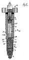
- FIG. 1 and 2 show, in addition to each other, an injection injector 1 according to the invention in its entirety.
- Combustion chamber side - based on an internal combustion engine, not shown, in the cylinder head of the injection injector 1 is installed injecting the combustion chamber - runs from the injection injector 1 in a nozzle body 2, followed by a conical transition part 4 and an intermediate plate 5, via a clamping nut 3 against an injector 6 are clamped.
- a pressure accumulator 7 is provided, which is closed at the opposite end to the nozzle body 2 via a closing piece 8, followed by a control valve 9 and this downstream an actuator 10.
- the pressure accumulator 7 is centrally penetrated by a control rod 11, which may also be hollow with advantage passes, which runs in a bore of the end piece 8 runs on a control chamber 12, which subsequently to the end piece 8 is covered by a plate 13, followed by the housing 14 of the control valve 9, which in turn is covered by a cover plate 15 which is penetrated by the actuating piston 16 of the actuator 10, which may be formed as a piezo or magnetic actuator, and preferably as shown, is designed as a piezo actuator.
- the pressure accumulator 7 is connected via the channels 19 and 20 with the control chamber 12, and according to the thus given pressurization of the control chamber 12, the control rod 11 in Direction loaded on the nozzle body 2. If the control piston 17 is displaced by energizing the actuator 10 against the force of the spring 18 and against hydraulic forces in its lower Abdichtlage, the connection of the control chamber 10 is shut off to the accumulator 7 and the control chamber 12 is via the channel 20 and further channels 21, 22 (see Fig. 4 ) is connected to the low pressure side, wherein the connection to the low pressure side is symbolized by the arrow 23.
- the pressure accumulator 7 communicates with a high-pressure source, for example a storage tube (common rail), via a channel 24 which opens onto the accumulator 7.
- a high-pressure source for example a storage tube (common rail)
- the pressure accumulator 7 is subdivided in the inventive solution into a control valve-side accumulator part 25 and a nozzle-side pressure accumulator part 26, wherein the high-pressure side connecting channel 24 on the control valve side Pressure accumulator part 25 opens and the two pressure storage parts 25, 26 are delimited by a flow control valve 28 against each other.
- the quantity limiting valve 28 is designed for the fuel throughput during operation of the internal combustion engine with maximum injection quantity and controls the connection between the pressure accumulator parts 25 and 26 when a threshold value lying above the aforementioned flow rate is exceeded.
- a support spring 30 is supported against the injector 6-position support plate 5 and enclosed in the illustrated embodiment by a stop sleeve 31 in its adjacent to the support plate 5 area, wherein the stop sleeve 31 is limited in against the force of the support spring 30 displaced locking piston 29 whose displacement and when plant the locking piston 29 is interrupted on the stop sleeve 31, the passage connection from the pressure accumulator 7 in the direction of the nozzle body 2.
- a further spring 32 is supported, which operates in the opposite direction to the support spring 30 and the control rod 11 is applied, which in turn is supported against the shaft 33 of a nozzle needle 34 which is guided in a nozzle needle bore 35 of the nozzle body 2 and in its illustrated Closing position to the nozzle body 2 in the end region of the nozzle needle bore 35 lying injection openings 36 abgrest.
- the nozzle needle 34 is loaded in its closed position in addition to the application of the spring 32 by the hydraulic overweight of the control rod 11 and in the region of its shaft 33 by a stop sleeve 37, through which a positionally secure connection of the nozzle needle 34 to the control rod 11 is made by the control rod 11 protrudes into the stop sleeve 37 and held suitably in this is, wherein the fit is selected such that on the one hand a sealing connection between the stop sleeve 37 and the control rod 11 and the nozzle needle shaft 33 is reached, on the other hand - for assembly - the control rod 11 from the shaft 33 of the nozzle needle 34 can be separated.
- the stroke of the nozzle needle 34 is limited in the opening direction, wherein the stop sleeve 37 is supported in its wegbegrenzenden stop position on the transition part 4.
- the nozzle-side pressure storage part 26 in open communication with the nozzle needle bore 35, as seen from Fig. 2 can be seen, wherein the nozzle needle 34 in its guide to the nozzle needle bore 35 a flow permitting, in particular polygonal, for example, triangular cross-section, so that in this guide area a free supply of fuel to the seating area of the nozzle needle 34 is given, the pressure-dependent in the over the stop sleeve 37 wegbe ancestrale open position is adjustable when the control rod 11 is not pressurized by the control chamber 12 and the control chamber 12 by energizing the actuator 10 and adjustment of the control piston 17 against the force of the spring 18 via the channels 20, 21 and 22 to the low pressure side connected.
- control rod 11 in the area of their expiring on the control chamber 12 end in the housing 14 sealingly and centering fixed end piece 8 and opposite by their position-fixed connection via the stop sleeve 37 at the Nozzle needle 34, so that the only a few millimeters thick control rod 11, which may optionally also be hollow, both in terms of vibrations and deformations is critical.
- the vibration behavior of the injection injector 1 with respect to pressure oscillations is improved by the internal pressure accumulator 7 integrated in the injection injector 1, wherein the accumulator 7 according to the invention advantageously also allows the integration of the flow control valve 28, through which the pressure accumulator 7 into its two pressure accumulator parts 25, 26 is divided and preferably forms a sliding guide for the control rod 11 with its locking piston 29.
- the locking piston 29 is with respect to its management tolerances to the injector 6, as well as optionally to the control rod 11 is formed so that in the period between successive injections, an amount of fuel from the control valve side pressure storage part 25 can pass to the nozzle-side pressure storage part 26, which corresponds to the respective regular injection quantity substantially and is below a predetermined threshold. Shown is the formation of the locking piston 29 on its side remote from the support spring 30 side with an end-side piston extension 38 in a diameter of the locking piston 29 in diameter reduced region 39 of the pressure accumulator 7 protrudes.
- the front-side piston extension 38 offers the possibility of injection rate development by the fact that in the overlap region of the piston extension 38 to the area 39 of the pressure accumulator 7 by tighter fit, by graduated circumferential contours or the like StudentsströmJ from pressure accumulator 25 to the pressure accumulator 26 with displacement of the locking piston 29 against the force of Support spring 30 are varied path-dependent.
- the leakage connection between the locking piston 29 and the control rod 11 largely To interrupt, it may be expedient to provide the locking piston 29 instead of, or in addition to the piston shoulder 38 with a flexible, in particular pressure-dependent einschnürbaren collar 64.
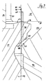
- the control piston 17, as the Fig. 3 and 4 show, designed as a mushroom piston, that is, with a conically widening head portion 40, which projects beyond the diameter 41 of the shaft 42.
- the conical head part 40 corresponds on the part of the housing 14 has a conical receptacle 43, and the head part 40 has on the one hand in the direction of the actuator 10 is determined by a sealing edge sealing diameter 44 against the covering cover plate 15 and on the other hand determined by a further sealing edge sealing diameter 45th against the housing 14 in the region of the conical receptacle 43.
- the sealing diameters 44 and 45 are each larger than the diameter 41 of the shank 42, so that in the direction of the respective sealing abutment pressure-dependent results in a supporting force.
- the respective inflow-side edge 46 and 48 adjoins the respective mating surface 50, 51 tapering to the sealing diameter 44 and 45, respectively Position of the control piston 17 from a tapered fürströmspalt, and depending on the gap height arise - based on the pressure in the stationary medium - pressure deviations, corresponding to the flow rate in the direction of a negative pressure.
- annular flanks 48, 49 on both sides of the lower, sealing diameter 44 narrow and inclined to the counter surface 51 on the receiving cone 43 only flat, and it is a broader outer edge 46 sought to counter surface 50.
- the solution according to the invention thus leads to a relatively simple injection injector, in which only small pressure oscillations result, in particular due to the integration of an accumulator into the injector, and in which only pressure peaks occur that are slightly above the system pressure, wherein, in addition, low pressure oscillation ranges are achieved , This allows high system pressures.
- Advantageous angular sizes in the sense of influencing the adjusting movements of the control piston 17 according to the invention are for the cone angle 52 of the receiving cone 43, for example, 90 °, at a cone angle 53 of lying in the inlet on the lower, sealing diameter 45 edge 48 of about 120 ° and a cone angle 54 of in the course of the lower sealing diameter 55 lying edge 49 of about 80 °, with other angular sizes with a comparable ratio of the angle to each other are within the scope of the invention.
- Fig. 5 shows an overall view of an injection injector 60, which in its overall construction largely according to the injection injector 1 Fig. 1 and 2 which is why the relevant reference signs have been adopted and to the description Fig. 1 and 2 is referenced.
- the injection injector 60 is provided with an actuator 10 designed as a magnetic actuator.
- the actuator piston 29 of the flow control valve 28 supporting support spring 30 is enclosed by the sleeve-shaped insert 61 and is supported against the intermediate plate 5 via a sleeve-shaped piece base from which is designated 62 and, as well as the support spring 30, the control rod 11 surrounds.
- the stop limit for the locking piston 29 via the insert 61 which has an engaging in the displacement of the locking piston 29 annular collar 63.
- the annular collar 63 is located on the housing 6 facing the end of the insert piece 61, and the flow control valve 28 is located with its locking piston 29 near the insert 61 facing the end of the housing 6.
Landscapes
- Engineering & Computer Science (AREA)
- Chemical & Material Sciences (AREA)
- Combustion & Propulsion (AREA)
- Mechanical Engineering (AREA)
- General Engineering & Computer Science (AREA)
- Physics & Mathematics (AREA)
- Fluid Mechanics (AREA)
- Fuel-Injection Apparatus (AREA)
- Nitrogen Condensed Heterocyclic Rings (AREA)
- Pharmaceuticals Containing Other Organic And Inorganic Compounds (AREA)
Claims (17)
- Injecteur comprenant :- un actionneur (10),- un espace de commande (12) alimenté par le biais d'une soupape de commande (9) actionnée par un actionneur (10),- un corps de buse (2) ayant au moins une ouverture d'injection (36),- une aiguille de buse (34) guidée dans le corps de buse (2), sollicitée par ressort dans sa position de fermeture vers l'ouverture d'injection (36) et pouvant être réglée par sollicitation en pression dans sa position d'ouverture vers l'ouverture d'injection,- un accumulateur de pression (7) situé entre la soupape de commande (9) et le corps de buse (2),- une barre de commande (11) s'étendant entre l'espace de commande (12) et l'aiguille de buse (34), traversant l'accumulateur de pression (7), sollicitant l'aiguille de buse (34) dans sa position de fermeture lors de la sollicitation en pression de l'espace de commande (12), et- une soupape de limitation de quantité (28), qui divise l'accumulateur de pression (7) en une partie d'accumulateur de pression (25) du côté de l'espace de commande, adjacente à la soupape de commande (9), connectée à une source de haute pression, et une partie d'accumulateur de pression (26) du côté de la buse, ouverte vers le corps de buse (2).
- Injecteur selon la revendication 1,
caractérisé en ce que
la soupape de limitation de quantité (28) présente un piston de verrouillage (29) déplaçable longitudinalement dans l'accumulateur de pression (7) et vers la barre de commande (11), qui est sollicité par ressort dans la direction de la partie d'accumulateur de pression (25) du côté de l'espace de commande. - Injecteur selon la revendication 1 ou 2,
caractérisé en ce que
le piston de verrouillage (29) de la soupape de limitation de quantité (28) présente une position de sortie sollicitée par ressort dans la direction de la partie d'accumulateur de pression (25) du côté de l'espace de commande, dans laquelle - en tant que position de verrouillage - la section transversale de débordement est bloquée de manière hermétique entre les parties d'accumulateur de pression. - Injecteur selon l'une quelconque des revendications 1 à 3,
caractérisé en ce que
le piston de verrouillage (29) forme un guide pour la barre de commande (11). - Injecteur selon l'une quelconque des revendications 1 à 4,
caractérisé en ce que
le piston de verrouillage (29) peut être déplacé dans une positon de verrouillage à l'encontre de sa sollicitation par le biais d'un ressort de support (30). - Injecteur selon l'une quelconque des revendications 1 à 5,
caractérisé en ce que le diamètre du piston de verrouillage (29) est supérieur au diamètre d'une pièce de piston (38) du côté frontal, qui vient en prise notamment par ajustement dans une portion de la partie d'accumulateur de pression du côté de l'espace de commande. - Injecteur selon l'une quelconque des revendications précédentes, caractérisé en ce que
le ressort (32) sollicitant l'aiguille de buse (34) dans la direction de sa position de fermeture et le ressort de support (30) supportant le piston de verrouillage (29) de la soupape de limitation de quantité (28) dans la direction opposée sont supportés contre une plaque intermédiaire (5) fixée au boîtier. - Injecteur selon l'une quelconque des revendications précédentes,
caractérisé en ce que
la barre de commande (11) est connectée de manière fixée en position à l'aiguille de buse (34). - Injecteur selon l'une quelconque des revendications 1 à 7,
caractérisé en ce que
la barre de commande (11) est creuse et est supportée de manière déplaçable transversalement et lâchement sur la tige (33) de l'aiguille de buse (34). - Injecteur selon la revendication 8,
caractérisé en ce que
la barre de commande (11) est fixée à une tige (33) de l'aiguille de buse (34) par le biais d'une douille de butée (37) limitant la course d'ouverture de l'aiguille de buse (34). - Injecteur selon la revendication 8 ou 10,
caractérisé en ce que
la tige de commande (11) est fixée de manière détachable dans la douille de butée (37) avec un ajustement étroit. - Injecteur selon l'une quelconque des revendications précédentes,
caractérisé en ce que
la soupape de commande (9) est réalisée sous forme de soupape à 3/2 voies, dont le piston de commande (17) est sollicité par ressort dans sa position de commande libérant la connexion de l'accumulateur de pression (7) à l'espace de commande (12). - Injecteur selon la revendication 12,
caractérisé en ce que
le piston de commande (14) de la soupape de commande (9) peut être sollicité par le biais de l'actionneur (10) dans la direction de sa position de verrouillage contre l'accumulateur de pression. - Injecteur selon la revendication 12 ou 13,
caractérisé en ce que
le piston de commande (14) de la soupape de commande (9) est réalisé sous forme de piston en champignon, qui dans sa position de verrouillage présente des diamètres (44, 45) d'étanchéité s'écartant par rapport au diamètre (41) de l'alésage de guidage recevant le piston de commande (17). - Injecteur selon la revendication 14,
caractérisé en ce que
les diamètres d'étanchéité (44, 45) du piston de commande (17) sont supérieurs au diamètre (41) de l'alésage de guidage recevant le piston de commande (17). - Injecteur selon l'une quelconque des revendications 12 à 15,
caractérisé en ce que
le piston de commande (17) est réalisé sous forme de piston à champignon, qui forme un flanc (46) se terminant vers le bord d'une fente d'étanchéité se rétrécissant en forme de cale dans la direction de débordement vers le diamètre d'étanchéité respectif (44). - Injecteur selon l'une quelconque des revendications précédentes,
caractérisé en ce que
le piston de verrouillage (29) est connecté de manière hermétique par rapport à la barre de commande (11) par le biais d'un collet (64) flexible pouvant être enfilé en fonction de la pression.
Applications Claiming Priority (2)
| Application Number | Priority Date | Filing Date | Title |
|---|---|---|---|
| DE102005056133A DE102005056133A1 (de) | 2005-11-23 | 2005-11-23 | Einspritzinjektor |
| PCT/EP2006/011093 WO2007059906A1 (fr) | 2005-11-23 | 2006-11-20 | Injecteur |
Publications (2)
| Publication Number | Publication Date |
|---|---|
| EP1952012A1 EP1952012A1 (fr) | 2008-08-06 |
| EP1952012B1 true EP1952012B1 (fr) | 2009-07-01 |
Family
ID=37831493
Family Applications (1)
| Application Number | Title | Priority Date | Filing Date |
|---|---|---|---|
| EP06818660A Not-in-force EP1952012B1 (fr) | 2005-11-23 | 2006-11-20 | Injecteur |
Country Status (4)
| Country | Link |
|---|---|
| EP (1) | EP1952012B1 (fr) |
| AT (1) | ATE435369T1 (fr) |
| DE (2) | DE102005056133A1 (fr) |
| WO (1) | WO2007059906A1 (fr) |
Families Citing this family (3)
| Publication number | Priority date | Publication date | Assignee | Title |
|---|---|---|---|---|
| DE102007025050B3 (de) * | 2007-05-29 | 2008-10-16 | L'orange Gmbh | Hochdruck-Einspritzinjektor für Brennkraftmaschinen mit einer knicklaststeigernden Steuerstangenabstützung über unter Hochdruck stehendem Kraftstoff |
| AT512277B1 (de) * | 2012-04-10 | 2013-07-15 | Bosch Gmbh Robert | Injektor eines modularen Common-Rail-Kraftstoffeinspritzsystems mit Durchflussbegrenzer |
| GB2559560B (en) * | 2017-02-08 | 2020-06-17 | Delphi Tech Ip Ltd | Control valve arrangement for a dual fuel injector |
Family Cites Families (13)
| Publication number | Priority date | Publication date | Assignee | Title |
|---|---|---|---|---|
| IT1232026B (it) * | 1989-02-28 | 1992-01-23 | Weber Srl | Dispositivo di iniezione del combustibile ad azionamento elettromagne tico per motori a ciclo diesel |
| JPH0466742A (ja) * | 1990-07-05 | 1992-03-03 | Yamaha Motor Co Ltd | 高圧燃料噴射式エンジンのアイドリング制御装置 |
| DE59310268D1 (de) * | 1992-12-23 | 2002-04-11 | Ganser Hydromag Ag Zuerich | Brennstoffeinspritzventil |
| EP0641931A1 (fr) * | 1993-09-06 | 1995-03-08 | Servojet Electronic Systems, Ltd. | Système d'injection de combustible à accumulateur |
| DE4340305C2 (de) * | 1993-11-26 | 1998-02-19 | Daimler Benz Ag | Kraftstoffeinspritzdüse für eine Brennkraftmaschine |
| JPH07332200A (ja) * | 1994-06-08 | 1995-12-22 | Hino Motors Ltd | ディーゼルエンジンの燃料噴射装置 |
| DE19640085C2 (de) * | 1996-09-28 | 2001-10-25 | Orange Gmbh | Sperrventil zur Durchflußmengenbegrenzung |
| DE19647304C1 (de) * | 1996-11-15 | 1998-01-22 | Daimler Benz Ag | Kraftstoffeinspritzanlage für eine Brennkraftmaschine |
| DE10147830B4 (de) * | 2001-09-27 | 2008-05-08 | L'orange Gmbh | Kraftstoffinjektor |
| DE10155973A1 (de) * | 2001-11-14 | 2003-05-22 | Bosch Gmbh Robert | Kraftstoffeinspritzeinrichtung für eine Brennkraftmaschine |
| DE10210282A1 (de) * | 2002-03-08 | 2003-09-25 | Bosch Gmbh Robert | Vorrichtung zum Einspritzen von Kraftstoff an stationären Verbrennungskraftmaschinen |
| JP4019934B2 (ja) * | 2002-12-26 | 2007-12-12 | 株式会社デンソー | 制御弁および燃料噴射弁 |
| FI117643B (fi) * | 2003-01-15 | 2006-12-29 | Waertsilae Finland Oy | Järjestely polttoaineen syöttölaitteistossa |
-
2005
- 2005-11-23 DE DE102005056133A patent/DE102005056133A1/de not_active Withdrawn
-
2006
- 2006-11-20 AT AT06818660T patent/ATE435369T1/de active
- 2006-11-20 DE DE502006004149T patent/DE502006004149D1/de active Active
- 2006-11-20 WO PCT/EP2006/011093 patent/WO2007059906A1/fr not_active Ceased
- 2006-11-20 EP EP06818660A patent/EP1952012B1/fr not_active Not-in-force
Also Published As
| Publication number | Publication date |
|---|---|
| ATE435369T1 (de) | 2009-07-15 |
| DE102005056133A1 (de) | 2007-05-24 |
| DE502006004149D1 (de) | 2009-08-13 |
| EP1952012A1 (fr) | 2008-08-06 |
| WO2007059906A1 (fr) | 2007-05-31 |
Similar Documents
| Publication | Publication Date | Title |
|---|---|---|
| EP2283226B1 (fr) | Injecteur de carburant pour moteurs a combustion interne | |
| EP2183476B1 (fr) | Soupape d'injection de carburant avec une étanchéité améliorée au niveau du siège d'étanchéité d'une soupape de commande à pression compensée | |
| WO2008155260A1 (fr) | Soupape de commande pour un injecteur de carburant, et injecteur de carburant | |
| WO2005019637A1 (fr) | Soupape d'injection de carburant commandee par une soupape pilote | |
| DE102004024527A1 (de) | Kraftstoffeinspritzeinrichtung | |
| EP2167808B1 (fr) | Injecteur haute pression pour moteurs à combustion interne à appui de tige de commande à charge de flambage croissante par l'intermédiaire de carburant haute pression | |
| WO2007012510A1 (fr) | Systeme d'injection de carburant pour moteur a combustion interne a injection directe de carburant | |
| WO2003074865A1 (fr) | Systeme pour moduler en pression le comportement d'injection | |
| EP1952012A1 (fr) | Injecteur | |
| EP2138704B1 (fr) | Injecteur de carburant | |
| DE102007034319A1 (de) | Injektor | |
| EP2655850B1 (fr) | Injecteur de carburant pour moteurs à combustion interne | |
| WO2007104590A1 (fr) | Soupape d'injection de carburant pour moteurs a combustion interne | |
| WO2004057180A1 (fr) | Soupape d'injection de carburant pour moteurs a combustion interne | |
| DE102007001365A1 (de) | Injektor mit Steuer- und Schaltkammer | |
| DE19947196A1 (de) | Kraftstoffeinspritzeinrichtung für Brennkraftmaschinen | |
| DE102006050033A1 (de) | Injektor, insbesondere Common-Rail-Injektor | |
| EP3184803B1 (fr) | Injecteur de carburant | |
| EP2726731B1 (fr) | Injecteur de carburant | |
| DE102012213535A1 (de) | Kraftstoffinjektor | |
| DE102006012842A1 (de) | Kraftstoffeinspritzventile für Brennkraftmaschinen | |
| EP2957760A1 (fr) | Ensemble de buses pour un injecteur de carburant et injecteur de carburant | |
| EP2085604A1 (fr) | Injecteur de carburant | |
| WO2008049726A1 (fr) | Dispositif de dosage de fluide | |
| WO2008049675A1 (fr) | Injecteur avec une soupape de commande à compensation de pression axiale |
Legal Events
| Date | Code | Title | Description |
|---|---|---|---|
| PUAI | Public reference made under article 153(3) epc to a published international application that has entered the european phase |
Free format text: ORIGINAL CODE: 0009012 |
|
| 17P | Request for examination filed |
Effective date: 20080521 |
|
| AK | Designated contracting states |
Kind code of ref document: A1 Designated state(s): AT BE BG CH CY CZ DE DK EE ES FI FR GB GR HU IE IS IT LI LT LU LV MC NL PL PT RO SE SI SK TR |
|
| GRAP | Despatch of communication of intention to grant a patent |
Free format text: ORIGINAL CODE: EPIDOSNIGR1 |
|
| GRAS | Grant fee paid |
Free format text: ORIGINAL CODE: EPIDOSNIGR3 |
|
| GRAA | (expected) grant |
Free format text: ORIGINAL CODE: 0009210 |
|
| AK | Designated contracting states |
Kind code of ref document: B1 Designated state(s): AT BE BG CH CY CZ DE DK EE ES FI FR GB GR HU IE IS IT LI LT LU LV MC NL PL PT RO SE SI SK TR |
|
| REG | Reference to a national code |
Ref country code: GB Ref legal event code: FG4D Free format text: NOT ENGLISH |
|
| REG | Reference to a national code |
Ref country code: CH Ref legal event code: EP |
|
| REG | Reference to a national code |
Ref country code: IE Ref legal event code: FG4D |
|
| REF | Corresponds to: |
Ref document number: 502006004149 Country of ref document: DE Date of ref document: 20090813 Kind code of ref document: P |
|
| PG25 | Lapsed in a contracting state [announced via postgrant information from national office to epo] |
Ref country code: SI Free format text: LAPSE BECAUSE OF FAILURE TO SUBMIT A TRANSLATION OF THE DESCRIPTION OR TO PAY THE FEE WITHIN THE PRESCRIBED TIME-LIMIT Effective date: 20090701 |
|
| NLV1 | Nl: lapsed or annulled due to failure to fulfill the requirements of art. 29p and 29m of the patents act | ||
| PG25 | Lapsed in a contracting state [announced via postgrant information from national office to epo] |
Ref country code: SE Free format text: LAPSE BECAUSE OF FAILURE TO SUBMIT A TRANSLATION OF THE DESCRIPTION OR TO PAY THE FEE WITHIN THE PRESCRIBED TIME-LIMIT Effective date: 20090701 Ref country code: EE Free format text: LAPSE BECAUSE OF FAILURE TO SUBMIT A TRANSLATION OF THE DESCRIPTION OR TO PAY THE FEE WITHIN THE PRESCRIBED TIME-LIMIT Effective date: 20090701 Ref country code: LT Free format text: LAPSE BECAUSE OF FAILURE TO SUBMIT A TRANSLATION OF THE DESCRIPTION OR TO PAY THE FEE WITHIN THE PRESCRIBED TIME-LIMIT Effective date: 20090701 Ref country code: ES Free format text: LAPSE BECAUSE OF FAILURE TO SUBMIT A TRANSLATION OF THE DESCRIPTION OR TO PAY THE FEE WITHIN THE PRESCRIBED TIME-LIMIT Effective date: 20091012 Ref country code: IS Free format text: LAPSE BECAUSE OF FAILURE TO SUBMIT A TRANSLATION OF THE DESCRIPTION OR TO PAY THE FEE WITHIN THE PRESCRIBED TIME-LIMIT Effective date: 20091101 Ref country code: FI Free format text: LAPSE BECAUSE OF FAILURE TO SUBMIT A TRANSLATION OF THE DESCRIPTION OR TO PAY THE FEE WITHIN THE PRESCRIBED TIME-LIMIT Effective date: 20090701 |
|
| REG | Reference to a national code |
Ref country code: IE Ref legal event code: FD4D |
|
| PG25 | Lapsed in a contracting state [announced via postgrant information from national office to epo] |
Ref country code: NL Free format text: LAPSE BECAUSE OF FAILURE TO SUBMIT A TRANSLATION OF THE DESCRIPTION OR TO PAY THE FEE WITHIN THE PRESCRIBED TIME-LIMIT Effective date: 20090701 Ref country code: PL Free format text: LAPSE BECAUSE OF FAILURE TO SUBMIT A TRANSLATION OF THE DESCRIPTION OR TO PAY THE FEE WITHIN THE PRESCRIBED TIME-LIMIT Effective date: 20090701 Ref country code: LV Free format text: LAPSE BECAUSE OF FAILURE TO SUBMIT A TRANSLATION OF THE DESCRIPTION OR TO PAY THE FEE WITHIN THE PRESCRIBED TIME-LIMIT Effective date: 20090701 |
|
| PG25 | Lapsed in a contracting state [announced via postgrant information from national office to epo] |
Ref country code: BG Free format text: LAPSE BECAUSE OF FAILURE TO SUBMIT A TRANSLATION OF THE DESCRIPTION OR TO PAY THE FEE WITHIN THE PRESCRIBED TIME-LIMIT Effective date: 20091001 Ref country code: PT Free format text: LAPSE BECAUSE OF FAILURE TO SUBMIT A TRANSLATION OF THE DESCRIPTION OR TO PAY THE FEE WITHIN THE PRESCRIBED TIME-LIMIT Effective date: 20091102 |
|
| PG25 | Lapsed in a contracting state [announced via postgrant information from national office to epo] |
Ref country code: CZ Free format text: LAPSE BECAUSE OF FAILURE TO SUBMIT A TRANSLATION OF THE DESCRIPTION OR TO PAY THE FEE WITHIN THE PRESCRIBED TIME-LIMIT Effective date: 20090701 Ref country code: IE Free format text: LAPSE BECAUSE OF FAILURE TO SUBMIT A TRANSLATION OF THE DESCRIPTION OR TO PAY THE FEE WITHIN THE PRESCRIBED TIME-LIMIT Effective date: 20090701 Ref country code: RO Free format text: LAPSE BECAUSE OF FAILURE TO SUBMIT A TRANSLATION OF THE DESCRIPTION OR TO PAY THE FEE WITHIN THE PRESCRIBED TIME-LIMIT Effective date: 20090701 Ref country code: DK Free format text: LAPSE BECAUSE OF FAILURE TO SUBMIT A TRANSLATION OF THE DESCRIPTION OR TO PAY THE FEE WITHIN THE PRESCRIBED TIME-LIMIT Effective date: 20090701 |
|
| PLBE | No opposition filed within time limit |
Free format text: ORIGINAL CODE: 0009261 |
|
| STAA | Information on the status of an ep patent application or granted ep patent |
Free format text: STATUS: NO OPPOSITION FILED WITHIN TIME LIMIT |
|
| BERE | Be: lapsed |
Owner name: L'ORANGE G.M.B.H. Effective date: 20091130 |
|
| PG25 | Lapsed in a contracting state [announced via postgrant information from national office to epo] |
Ref country code: SK Free format text: LAPSE BECAUSE OF FAILURE TO SUBMIT A TRANSLATION OF THE DESCRIPTION OR TO PAY THE FEE WITHIN THE PRESCRIBED TIME-LIMIT Effective date: 20090701 |
|
| 26N | No opposition filed |
Effective date: 20100406 |
|
| PG25 | Lapsed in a contracting state [announced via postgrant information from national office to epo] |
Ref country code: MC Free format text: LAPSE BECAUSE OF NON-PAYMENT OF DUE FEES Effective date: 20091130 |
|
| REG | Reference to a national code |
Ref country code: FR Ref legal event code: ST Effective date: 20100730 |
|
| PG25 | Lapsed in a contracting state [announced via postgrant information from national office to epo] |
Ref country code: GR Free format text: LAPSE BECAUSE OF FAILURE TO SUBMIT A TRANSLATION OF THE DESCRIPTION OR TO PAY THE FEE WITHIN THE PRESCRIBED TIME-LIMIT Effective date: 20091002 Ref country code: FR Free format text: LAPSE BECAUSE OF NON-PAYMENT OF DUE FEES Effective date: 20091130 Ref country code: BE Free format text: LAPSE BECAUSE OF NON-PAYMENT OF DUE FEES Effective date: 20091130 |
|
| PG25 | Lapsed in a contracting state [announced via postgrant information from national office to epo] |
Ref country code: LU Free format text: LAPSE BECAUSE OF NON-PAYMENT OF DUE FEES Effective date: 20091120 |
|
| PG25 | Lapsed in a contracting state [announced via postgrant information from national office to epo] |
Ref country code: HU Free format text: LAPSE BECAUSE OF FAILURE TO SUBMIT A TRANSLATION OF THE DESCRIPTION OR TO PAY THE FEE WITHIN THE PRESCRIBED TIME-LIMIT Effective date: 20100102 |
|
| PG25 | Lapsed in a contracting state [announced via postgrant information from national office to epo] |
Ref country code: TR Free format text: LAPSE BECAUSE OF FAILURE TO SUBMIT A TRANSLATION OF THE DESCRIPTION OR TO PAY THE FEE WITHIN THE PRESCRIBED TIME-LIMIT Effective date: 20090701 |
|
| PG25 | Lapsed in a contracting state [announced via postgrant information from national office to epo] |
Ref country code: CY Free format text: LAPSE BECAUSE OF FAILURE TO SUBMIT A TRANSLATION OF THE DESCRIPTION OR TO PAY THE FEE WITHIN THE PRESCRIBED TIME-LIMIT Effective date: 20090701 |
|
| PGFP | Annual fee paid to national office [announced via postgrant information from national office to epo] |
Ref country code: DE Payment date: 20121121 Year of fee payment: 7 Ref country code: CH Payment date: 20121122 Year of fee payment: 7 |
|
| PGFP | Annual fee paid to national office [announced via postgrant information from national office to epo] |
Ref country code: GB Payment date: 20121120 Year of fee payment: 7 Ref country code: IT Payment date: 20121122 Year of fee payment: 7 |
|
| PGFP | Annual fee paid to national office [announced via postgrant information from national office to epo] |
Ref country code: AT Payment date: 20121113 Year of fee payment: 7 |
|
| REG | Reference to a national code |
Ref country code: CH Ref legal event code: PL |
|
| REG | Reference to a national code |
Ref country code: AT Ref legal event code: MM01 Ref document number: 435369 Country of ref document: AT Kind code of ref document: T Effective date: 20131120 |
|
| GBPC | Gb: european patent ceased through non-payment of renewal fee |
Effective date: 20131120 |
|
| PG25 | Lapsed in a contracting state [announced via postgrant information from national office to epo] |
Ref country code: CH Free format text: LAPSE BECAUSE OF NON-PAYMENT OF DUE FEES Effective date: 20131130 Ref country code: LI Free format text: LAPSE BECAUSE OF NON-PAYMENT OF DUE FEES Effective date: 20131130 |
|
| PG25 | Lapsed in a contracting state [announced via postgrant information from national office to epo] |
Ref country code: AT Free format text: LAPSE BECAUSE OF NON-PAYMENT OF DUE FEES Effective date: 20131120 Ref country code: DE Free format text: LAPSE BECAUSE OF NON-PAYMENT OF DUE FEES Effective date: 20140603 Ref country code: IT Free format text: LAPSE BECAUSE OF NON-PAYMENT OF DUE FEES Effective date: 20131120 |
|
| REG | Reference to a national code |
Ref country code: DE Ref legal event code: R119 Ref document number: 502006004149 Country of ref document: DE Effective date: 20140603 |
|
| PG25 | Lapsed in a contracting state [announced via postgrant information from national office to epo] |
Ref country code: GB Free format text: LAPSE BECAUSE OF NON-PAYMENT OF DUE FEES Effective date: 20131120 |