EP1952851A1 - Gleitmaschine - Google Patents
Gleitmaschine Download PDFInfo
- Publication number
- EP1952851A1 EP1952851A1 EP08001892A EP08001892A EP1952851A1 EP 1952851 A1 EP1952851 A1 EP 1952851A1 EP 08001892 A EP08001892 A EP 08001892A EP 08001892 A EP08001892 A EP 08001892A EP 1952851 A1 EP1952851 A1 EP 1952851A1
- Authority
- EP
- European Patent Office
- Prior art keywords
- point
- angle
- gliding
- pair
- spatula
- Prior art date
- Legal status (The legal status is an assumption and is not a legal conclusion. Google has not performed a legal analysis and makes no representation as to the accuracy of the status listed.)
- Granted
Links
- 238000005304 joining Methods 0.000 claims description 6
- XLYOFNOQVPJJNP-UHFFFAOYSA-N water Substances O XLYOFNOQVPJJNP-UHFFFAOYSA-N 0.000 claims description 4
- 210000002683 foot Anatomy 0.000 description 62
- 102100036300 Golgi-associated olfactory signaling regulator Human genes 0.000 description 10
- 101710204059 Golgi-associated olfactory signaling regulator Proteins 0.000 description 10
- 210000003371 toe Anatomy 0.000 description 4
- 210000003423 ankle Anatomy 0.000 description 3
- 230000027455 binding Effects 0.000 description 3
- 238000009739 binding Methods 0.000 description 3
- 210000003127 knee Anatomy 0.000 description 3
- 210000001624 hip Anatomy 0.000 description 2
- 238000000926 separation method Methods 0.000 description 2
- 238000004519 manufacturing process Methods 0.000 description 1
- 238000003825 pressing Methods 0.000 description 1
- 238000009987 spinning Methods 0.000 description 1
Images


Classifications
-
- A—HUMAN NECESSITIES
- A63—SPORTS; GAMES; AMUSEMENTS
- A63C—SKATES; SKIS; ROLLER SKATES; DESIGN OR LAYOUT OF COURTS, RINKS OR THE LIKE
- A63C5/00—Skis or snowboards
- A63C5/006—Appearance of the ski-tip, the rear end or the upper ski-edge
-
- A—HUMAN NECESSITIES
- A63—SPORTS; GAMES; AMUSEMENTS
- A63C—SKATES; SKIS; ROLLER SKATES; DESIGN OR LAYOUT OF COURTS, RINKS OR THE LIKE
- A63C5/00—Skis or snowboards
- A63C5/04—Structure of the surface thereof
- A63C5/0405—Shape thereof when projected on a plane, e.g. sidecut, camber, rocker
-
- A—HUMAN NECESSITIES
- A63—SPORTS; GAMES; AMUSEMENTS
- A63C—SKATES; SKIS; ROLLER SKATES; DESIGN OR LAYOUT OF COURTS, RINKS OR THE LIKE
- A63C5/00—Skis or snowboards
- A63C5/04—Structure of the surface thereof
- A63C5/0405—Shape thereof when projected on a plane, e.g. sidecut, camber, rocker
- A63C5/0411—Shape thereof when projected on a plane, e.g. sidecut, camber, rocker asymmetric
-
- B—PERFORMING OPERATIONS; TRANSPORTING
- B63—SHIPS OR OTHER WATERBORNE VESSELS; RELATED EQUIPMENT
- B63B—SHIPS OR OTHER WATERBORNE VESSELS; EQUIPMENT FOR SHIPPING
- B63B32/00—Water sports boards; Accessories therefor
- B63B32/30—Water skis fastened to the user's feet; Accessories specially adapted therefor
-
- B—PERFORMING OPERATIONS; TRANSPORTING
- B63—SHIPS OR OTHER WATERBORNE VESSELS; RELATED EQUIPMENT
- B63B—SHIPS OR OTHER WATERBORNE VESSELS; EQUIPMENT FOR SHIPPING
- B63B32/00—Water sports boards; Accessories therefor
- B63B32/30—Water skis fastened to the user's feet; Accessories specially adapted therefor
- B63B32/35—Bindings
Definitions
- the present invention relates to gliding machines. It relates in particular to gliding machines which consist of a pair of gliding boards independent of each other and which are each attached to one of the feet of the user.
- skis Such gliding machines are known and are generally called skis.
- skis There is a multitude of skis adapted to practice on snow, such as alpine skis, cross-country skis, skis, short skis, etc ...
- skis There are also skis adapted for practice on the snow.
- water such as water skis. All skis have in common to have an elongated shape along a longitudinal axis, and to provide means participating in fixing a foot on said ski. These means participating in the fixing of a foot on the ski are placed in a central area of the ski and ensure a fixation of the foot in the longitudinal axis of the ski.
- All skis also have in common the fact of being used to slide in a given direction D, the axis of sliding, which is parallel to the longitudinal axis of the ski.
- D the axis of sliding
- the user keeps his skis flat while maintaining his support in the center of the ski; to turn left, he moves his supports on the left side of the ski by pressing on the left edge, and to go to the right, he moves his supports on the right edge of the ski.
- the skier will pass successively from one square to the other by lateral supports.
- the joints of the ankles, knees, hips and spine the user can easily change its support, and pass them back and forth, and vice versa, while maintaining its balance.
- the human body is not intended for lateral flexions.
- the ankles, knees and spine offer only a very small amount of flexion on the sides. So that, to pass his support from left to right, respectively from right to left, the alpine skier engages his whole body to the right, respectively to the left. In doing so, he places himself in lateral imbalance. This is why two sticks are needed for a skier's balance, and it may be easier for him to turn when he has a high speed.
- the invention aims to provide a gliding machine that overcomes the disadvantages of the prior art.
- the object of the invention is in particular to provide a new gliding machine that better corresponds to human morphology.
- Another object of the invention is to provide a new gliding apparatus, which allows easier and more accessible use of wide gliding boards.
- the invention also aims to provide a new gliding device that ensures a better balance to the user and even at low speed.
- the object of the invention is achieved by providing a pair of gliding boards, intended to be used together, without connection with each other, by a user to slide in a sliding direction, D, said pair of boards comprising a first board, which has an elongate shape along a first longitudinal axis and has first means participating in fixing the left foot of said user to said first board according to a first attachment axis; said pair of planks also comprising a second plank, which has an elongate shape along a second longitudinal axis and has second means participating in fixing the right foot of said user to said second plank along a second attachment axis; characterized in that the first axis of attachment makes with the first longitudinal axis a first angle, ⁇ 1, in that the second axis of attachment makes with the second longitudinal axis a second angle, ⁇ 2, in that the angle ⁇ 1 and ⁇ 1 angle ⁇ 2 are oriented in the same direction; and in that at least one of said angles ⁇ 1 and ⁇ 2 is non-zero.
- the angle ⁇ 1 and the angle ⁇ 2 have a value between 0 ° and 30 °.
- the angle ⁇ 1 and the angle ⁇ 2 are oriented in the direction of clockwise.
- the angle ⁇ 1 and the angle ⁇ 2 are oriented in the opposite direction of the clockwise.
- the gliding boards according to the invention are wide, even at the level of the pad, that is to say the area where the feet of the user are placed.
- the gliding boards according to the invention comprise offset side lines, that is to say that the "hollow” of the left side line and the “hollow” of the right side line are not placed longitudinally at the same level.
- One of the ways to achieve this effect is to fully shift the entire right edge relative to the left edge.
- the contour of each of the gliding boards is defined by a closed curve passing, on the one hand, by a left spatula point and a right spatula point, both placed at level of the spatula and secondly, by a point left heel and a right heel point, both placed at the heel; the said points being further defined by the fact that they constitute concavity / convexity inversion points of the contour and by the fact that in the portion of the contour joining the left spatula point and the left heel point, called the dimension line left, respectively in the portion of the contour joining the right spatula point and the right heel point, called line of right side, the contour is always concave; said gliding board being characterized in that the line passing through the left spatula point and the right spatula point makes with said first longitudinal axis an angle ⁇ s in the clockwise direction or in the opposite direction clockwise which is not equal to 90 ° and in that the line passing the left heel point and the right heel point made with said
- the pair of gliding boards according to the invention can be used on snow or on water.
- the means participating in the attachment of the left foot and the right foot may comprise threaded inserts anchored in the gliding boards or an interface fixed on each of said gliding board; said interface being adapted to receive retaining means of a sports shoe.
- These means participating in fixing may also comprise a footwear device designed to receive the left foot or the right foot.
- These means may also include a strap designed to receive the right foot or the left foot.
- the feet of the user are not in the axis of the boards, or axis of the right slide. They make an angle so that the heels are closest to one of the edges and the toes are closest to the other edge.
- the angle that the axis of sliding with the axis of the foot is between 5 ° and 30 °.
- the two gliding boards are wide with a width at the attachment of the feet which is between 120 mm and 160 mm.
- the gliding boards are wide, they are easy to maneuver. Indeed, because of the placement of the feet at a non-zero angle, there are always either toes or heels that are close to the edges inside the turn. To make a comparison, a pair of gliding boards according to the invention will be much easier to maneuver, and therefore much more accessible to all types of users, than a pair of skis of equal width skate.
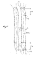
- the figure 1 describes a pair of skis according to the prior art.
- Each of the skis has an elongated shape along a longitudinal axis which is parallel to the sliding direction, D.
- the outline of each ski is defined as a closed curve which has the following characteristics.
- the line of maximum width measured transversely to the longitudinal axis makes the separation between the spatula and the body of the ski.
- the line of maximum width measured transversely to the longitudinal axis makes the separation between the heel and the ski body.
- the geometry of the ski body contour that is to say of the portion delimited by the line of maximum front width and the maximum rear width line, plays a very important role in the behavior of the ski.
- the left part of this outline is called the left side line, and the right side is the right side line.
- the left side line and the right side line are concave.
- the left side line and the right side line are symmetrical with respect to the longitudinal axis.
- the pair of skis comprises a right ski and a left ski different from each other
- the right and left skis of the ski pairs known from the prior art are always symmetrical with respect to a plane of symmetry, P.
- this plane of symmetry, P is a vertical plane which contains the sliding direction.
- the skis are equipped with shoe retaining means, which are fixed on the skis at the level of the pad, that is to say at the level of the minimum width area of the ski.
- shoe retaining means which are fixed on the skis at the level of the pad, that is to say at the level of the minimum width area of the ski.
- MC transverse line
- the positioning of the retaining means of the shoes relative to the ski is such that, when the shoe is in place on the ski, the effective medium of the shoe, is close to the line "middle of shoe” MC.
- the shoe retaining means are placed so that the foot of the user is placed in the direction of sliding.
- shoe retaining means on a ski which comprise devices for varying the angle of the foot of the user relative to the longitudinal axis of the ski.
- these devices are designed to improve the skier's comfort in the case where the latter has articular deformities, for example when his feet make a particularly large angle with respect to each other.
- the adjustment of these devices ensures that the right foot position is symmetrical with the position of the left foot relative to the plane of symmetry, P.
- the edges of the ski are the lower edges of the ski along the left and right side lines.
- the user leans on the inside edges of the turn, ie the left edges of each skis for a left turn and the right edges for a right turn.
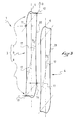
- the figure 2 described in plan view, a gliding board according to a first embodiment of the invention.
- the geometry of the gliding board's contour is defined by a closed curve. This curve goes through at least four inflection points. Two of these inflection points are located near the front end of the ski, this is the left spatula point 11 and right spatula point 12. Two other inflection points are located near the rear end of the ski, it is about the left heel point 13 and the right heel point 14. The positioning of these points is such that between the left spatula point 11 and the left heel point 13, on the one hand, and between the spatula point right 12 and right heel point 14, on the other hand, there is no other point of inflection.
- the portion of the contour of the gliding board which connects the left spatula point 11 to the left heel point 13 is called left side line 15.
- the portion of the contour which connects the right spatula point 12 to the right heel point 14 is called the dimension line right 16.
- the left side line and the right side line are concave.
- the concavity of the left and right side lines is not necessarily constant along the right line, but to ensure a healthy behavior of the gliding boards, if the concavity evolves, it evolves regularly.
- the shape of the contours of the spatula and heel can take any form possible.
- the front end line 18 is the line that passes through the left spatula point 11 and the right spatula point 12. This line 18 makes an angle ⁇ s with the longitudinal axis.
- the rear end line 19 is the line that passes through the left heel point 13 and the right heel point 14. This line 19 makes an angle ⁇ t with the longitudinal axis.
- the angle ⁇ s and the angle ⁇ t are both different from 90 °. These angles may be equal or not. On the other hand, these angles are anyway oriented in the same direction. In the embodiment described in figure 2 the angle ⁇ s is oriented counterclockwise and has a value between 5 ° and 85 °. The angle ⁇ t is also oriented in the opposite direction of the clockwise and has a value substantially equal to ⁇ s.
- the half-width of the gliding board at the left spatula point 11, Lsg, and the half-width of the gliding board at the right spatula point 12, Lsd are respectively the maximum half widths of the gliding board at its front end, the left side and the right side.
- the half widths of the gliding board at the left heel point 13, Ltg, and the right heel point 14, Ltd are respectively the maximum half widths of the gliding board at its rear end, the left side and right side.
- the line where the minimum left half width, Lgm, is found corresponds to the "trough" of the left side line.
- the line where the minimum right half-width, Ldm, is located corresponds to the hollow of the right-hand side line. Longitudinally, the "trough" of the left side line is further ahead than the "trough" of the right side line.
- the two gliding boards are wide with a width at the attachment of the feet which is between 120 mm and 160 mm.
- the width at the foot attachment is slightly greater than the sum of the minimum left half width, Lgm, and the minimum right half width, Ldm.
- the length of each of the sliding boards can be between 900 mm and 1700 mm, good results are obtained with lengths between 1300 mm and 1500 mm.
- the figure 3 describes a pair of gliding boards according to a second embodiment of the invention, it is a pair of gliding boards for "regular" 1.
- the pair of gliding boards 1 comprises a first gliding board 3 intended to be fixed to the left foot of the user and a second gliding board 4 intended to be fixed to the right foot of the user.
- the first gliding board 3 has an elongated shape along a first longitudinal axis 5, which is parallel to the sliding direction, D, when the gliding machine is used. It is broken down into three parts, a spatula at the front end of the gliding board 3, a heel 8 at the rear end and a body 9 between the spatula 7 and the heel 8.
- the first gliding board of the figure 3 is particularized from the gliding board of the figure 2 in that the angle ⁇ s and the angle ⁇ t are equal and in that the contour of the spatula and that of the heel are different.
- the second gliding board 4 has an elongate shape along a second longitudinal axis 6, which is parallel to the sliding direction, D, when the pair of gliding boards 1 is used.
- the second gliding board 4 is identical to the first gliding board 3, and all that will be said thereafter for the first gliding board 3 also applies to the second gliding board 4, unless otherwise specified.
- the first gliding board also comprises means participating in fixing the left foot of the user to said first board. These means consist of a plurality of threaded inserts fixed inside the gliding board. These inserts 17 are put in place during the manufacture of the gliding board. Before using the gliding board simply mount the retainers on these inserts.
- the means participating in fixing the user's left foot to the first gliding board 3 are such as to allow the user's left foot to be fixed according to a first fastening axis 20 which makes with the first longitudinal axis 5 an angle ⁇ 1 which is non-zero and which is oriented in the direction of clockwise.
- the angle ⁇ 1 is between 0 and 30 °, and more particularly between 5 and 30 °. In the example described in figure 3 the angle ⁇ 1 is equal to 12 °.
- inserts 17 are also anchored in the second gliding board 4, and they allow the attachment of retaining means of a shoe.
- these inserts 17 are positioned in such a way that the user's right foot is fixed to the second gliding board 4 along a second fastening axis 21 which makes with the second longitudinal axis 6 a angle ⁇ 2 which is non-zero and oriented in the direction of clockwise.
- the angle ⁇ 2 is between 0 and 30 °, and more particularly between 5 and 30 °. In the example described in figure 3 the angle ⁇ 2 is equal to 12 °.
- the inserts 17 can receive any shoe retaining means.
- the safety bindings that are common in alpine skiing today will be used.
- the figure 3 describes the pair of "regular" gliding boards 1 in its position of use, that is to say respecting the relative position of the first and second gliding boards with respect to each other, when the craft glides in a straight line.
- the pair of boards "regular" 1, is particularly intended for users “regular”.
- the "regular" user When sliding in a straight line with a pair of gliding boards according to the invention, the "regular" user keeps his two feet separated from each other by a distance at his convenience.
- the offset of the feet relative to each other is a function of a multitude of factors, for example, the height of the user, its speed, its technical level, and also the local conditions of Track.
- the figure 4 describes a gliding machine according to a third embodiment of the invention, it is a gliding machine for "goofy" 2.
- the "goofy" gliding apparatus 2 consists of a pair of gliding boards, each being equipped with means for retaining a shoe. It includes a first gliding board 3 intended to be fixed to the left foot of the user and a second gliding board 4 intended to be fixed to the right foot of the user.
- the first gliding board 3, respectively the second gliding board 4 has an elongated shape along a first longitudinal axis 5, respectively a second longitudinal axis 6, which lie parallel to the sliding direction, D, when the machine sliding is used. They are broken down into three parts, a spatula at the front end of the gliding board 3, a heel 8 at the rear end and a body 9 between the spatula 7 and the heel 8.
- the first gliding board 3 and the second gliding board 4 are identical to each other. On the other hand, in the example described in figure 4 , they are symmetrical sliding boards presented at the figure 3 .
- the geometry of the gliding board's contour is defined by a closed curve. This curve goes through at least four inflection points. Two of these inflection points are located near the front end of the ski, this is the left spatula point 11 and right spatula point 12. Two other inflection points are located near the rear end of the ski, it is about the left heel point 13 and the right heel point 14. The positioning of these points is such that between the left spatula point 11 and the left heel point 13, on the one hand, and between the spatula point right 12 and right heel point 14, on the other hand, there is no other point of inflection. In this case, between the left spatula point 11 and the left heel point 13, respectively between the right spatula point 12 and the right heel point 14, the left side line 15, respectively the right side line 16, is always concave .
- the contour of the spatula 7 that is to say the portion of the contour delimited by the left spatula point 11 and the right spatula point 12, has, meanwhile, another point of inflection between the two previous points .
- the contour of the heel 8 has a shape similar to that of the contour of the spatula 7.
- the front end line 18 passing through the left spatula point 11 and the right spatula point 12 made with the longitudinal axis an angle ⁇ s, between 20 ° and 60 °.
- the left retaining means 22, respectively the right retaining means 23, are fixed to the first gliding board 3, respectively to the second gliding board 4, so that the left foot of the user, respectively the right foot make with the first longitudinal axis 5, respectively the second longitudinal axis 6, an angle ⁇ 1, respectively an angle ⁇ 2.
- the angle ⁇ 1 and the angle ⁇ 2 are non-zero and they are both oriented in the opposite direction of the clockwise.
- the angles ⁇ 1 and ⁇ 2 are equal and between 5 ° and 30 °. Good results are obtained with angles ⁇ 1 and ⁇ 2 equal to 12 °. When the angles ⁇ 1 and ⁇ 2 are equal, it is ensured that during practice, the right and left feet will remain parallel to each other.
- angles ⁇ 1 and ⁇ 2 are in no way a limiting feature of the invention and it is possible to envisage gliding machines whose angles ⁇ 1 and ⁇ 2 are not equal. In this case the feet will no longer be exactly parallel. We can make this choice for reasons of comfort or for reasons of performance.
- the figure 4 shows the footprint of the left foot 26 and the footprint of the right foot 27 of the user.
- the front of the left foot is close to the left edge of the first gliding board, respectively close to the left edge of the second gliding board.
- the rear of the left foot is close to the right edge of the first gliding board, respectively close to the right edge of the second gliding board.
- the gliding device “goofy” 2 is particularly intended for users “goofy”. It is used as follows: When sliding in a straight line with a "goofy” gliding machine, the user keeps his right foot in front of his left foot, the offset of the two feet one with respect to the other is a function of a multitude of factors, for example, the height of the user, its speed, its technical level, and also the local conditions of the track. To start a turn to the left, the user must bear on the edges inside the turn, that is to say the left edges of each board gliding. To do this, he tilts the weight of his body forward and therefore he brings his supports to the level of his toes. It operates a forward flexion that combines with a decrease in the offset between the right foot and the left foot. For the goofy user, the left turn is the front turn.
- the user To be able to start a turn to the right, the user must bear on the edges inside the turn, that is to say, in this case, the right edges of each of the gliding boards. To do this, he moves the weight of his body backwards and therefore he brings his supports to the level of his heels. To keep the balance, it increases the shift between the right foot and the left foot.
- the user When in the "front” position, the user places the weight of his body in support on the two “front” support zones 24, each of them being fixed on one of the sliding boards.
- the "front” support zones 24 are placed close to the right edge, while they are placed close to the left edge for a "goofy” gliding machine 2 .
- the user When in the "back” position, the user places the weight of his body in support on the two support zones "back” 25, each of them being fixed on one of the gliding boards.
- the "back” support zones 25 are placed close to the left edge, while they are placed close to the right edge for a "goofy” gliding machine 2 .
- the support zones "front” 24 and “back” 25 are placed close to the lines of half-width minimum left, Lgm, and right, Ldm. In addition, if one connects between them by a straight line, the support zones "front” 24 and “back” 25, this line makes with the longitudinal axis an angle which is close to the angle ⁇ s and the angle .delta.t.
Landscapes
- Chemical & Material Sciences (AREA)
- Engineering & Computer Science (AREA)
- Combustion & Propulsion (AREA)
- Mechanical Engineering (AREA)
- Ocean & Marine Engineering (AREA)
- Road Paving Structures (AREA)
- Footwear And Its Accessory, Manufacturing Method And Apparatuses (AREA)
Applications Claiming Priority (1)
| Application Number | Priority Date | Filing Date | Title |
|---|---|---|---|
| FR0700766A FR2912066B1 (fr) | 2007-02-02 | 2007-02-02 | Engin de glisse |
Publications (2)
| Publication Number | Publication Date |
|---|---|
| EP1952851A1 true EP1952851A1 (de) | 2008-08-06 |
| EP1952851B1 EP1952851B1 (de) | 2012-06-27 |
Family
ID=38556389
Family Applications (1)
| Application Number | Title | Priority Date | Filing Date |
|---|---|---|---|
| EP08001892A Not-in-force EP1952851B1 (de) | 2007-02-02 | 2008-02-01 | Paar Gleitbretter mit Bindungsachsen die einen Winkel mit der Brettachse bilden und in der gleichen Richtung orientiert sind |
Country Status (3)
| Country | Link |
|---|---|
| US (1) | US7562894B2 (de) |
| EP (1) | EP1952851B1 (de) |
| FR (1) | FR2912066B1 (de) |
Cited By (4)
| Publication number | Priority date | Publication date | Assignee | Title |
|---|---|---|---|---|
| EP2248560A1 (de) * | 2009-05-06 | 2010-11-10 | Zai AG | Schneegleitbrett |
| WO2010108461A3 (en) * | 2009-04-15 | 2011-02-17 | Storkan Pavel | Sport equipment for snow ride |
| FR2991883A1 (fr) * | 2012-06-19 | 2013-12-20 | Salomon Sas | Paire de skis asymetriques |
| WO2016024920A1 (en) * | 2014-08-14 | 2016-02-18 | Grabar Andrej | Skis and snowboard with specific sidecuts |
Families Citing this family (1)
| Publication number | Priority date | Publication date | Assignee | Title |
|---|---|---|---|---|
| US9138629B2 (en) * | 2013-03-15 | 2015-09-22 | Brian Rosenberger | Rib-stiffened sports board |
Citations (7)
| Publication number | Priority date | Publication date | Assignee | Title |
|---|---|---|---|---|
| US3121892A (en) * | 1963-04-24 | 1964-02-25 | Carl H Plumlee | Floating skis |
| DE9104587U1 (de) * | 1991-04-15 | 1991-07-11 | Schürer, Walter, Dr., 8000 München | Kurzski |
| WO1991012056A1 (de) * | 1990-02-08 | 1991-08-22 | Tmc Corporation | Ski mit elastischer verankerung der skibindungen |
| FR2660567A1 (fr) * | 1990-04-04 | 1991-10-11 | Rohrmoser Alois Skifabrik | Ski alpin avec un rapport determine entre la largeur et la longueur. |
| FR2690351A1 (fr) * | 1992-04-27 | 1993-10-29 | Patrick Balmain | Equipement de sport de glisse sur neige du type constitué par une planche unique. |
| US6283491B1 (en) * | 1997-03-06 | 2001-09-04 | Maclean-Esna, L.P. | Sportboard fastener |
| US6394482B1 (en) * | 1999-09-09 | 2002-05-28 | Ski Logic, Llc | Snow skis having asymmetrical edges |
Family Cites Families (7)
| Publication number | Priority date | Publication date | Assignee | Title |
|---|---|---|---|---|
| US4141570A (en) * | 1977-10-17 | 1979-02-27 | Sudmeier James L | Adjustable connection between ski and binding |
| US5286051A (en) * | 1990-04-04 | 1994-02-15 | Atomic Skifabrik Alois Rohrmoser | Alpine ski with a minimum width and specific width/length ratio |
| US5816590A (en) * | 1997-04-02 | 1998-10-06 | Uniboard Corporation | Nordic skiboard |
| US5984324A (en) * | 1997-08-14 | 1999-11-16 | Voile Manufacturing | Touring snowboard |
| US7178821B2 (en) * | 2002-02-15 | 2007-02-20 | Miller Sports International, Inc. | Universal ski and snowboard binding |
| FR2855427B1 (fr) * | 2003-06-02 | 2005-08-26 | Salomon Sa | Ski prevu pour la pratique du ski alpin |
| US7159875B2 (en) * | 2003-11-21 | 2007-01-09 | Keahi Seymour | Articulated-severable snowboard also useable as emergency snowshoes |
-
2007
- 2007-02-02 FR FR0700766A patent/FR2912066B1/fr not_active Expired - Fee Related
-
2008
- 2008-02-01 US US12/024,426 patent/US7562894B2/en not_active Expired - Fee Related
- 2008-02-01 EP EP08001892A patent/EP1952851B1/de not_active Not-in-force
Patent Citations (7)
| Publication number | Priority date | Publication date | Assignee | Title |
|---|---|---|---|---|
| US3121892A (en) * | 1963-04-24 | 1964-02-25 | Carl H Plumlee | Floating skis |
| WO1991012056A1 (de) * | 1990-02-08 | 1991-08-22 | Tmc Corporation | Ski mit elastischer verankerung der skibindungen |
| FR2660567A1 (fr) * | 1990-04-04 | 1991-10-11 | Rohrmoser Alois Skifabrik | Ski alpin avec un rapport determine entre la largeur et la longueur. |
| DE9104587U1 (de) * | 1991-04-15 | 1991-07-11 | Schürer, Walter, Dr., 8000 München | Kurzski |
| FR2690351A1 (fr) * | 1992-04-27 | 1993-10-29 | Patrick Balmain | Equipement de sport de glisse sur neige du type constitué par une planche unique. |
| US6283491B1 (en) * | 1997-03-06 | 2001-09-04 | Maclean-Esna, L.P. | Sportboard fastener |
| US6394482B1 (en) * | 1999-09-09 | 2002-05-28 | Ski Logic, Llc | Snow skis having asymmetrical edges |
Cited By (5)
| Publication number | Priority date | Publication date | Assignee | Title |
|---|---|---|---|---|
| WO2010108461A3 (en) * | 2009-04-15 | 2011-02-17 | Storkan Pavel | Sport equipment for snow ride |
| EP2248560A1 (de) * | 2009-05-06 | 2010-11-10 | Zai AG | Schneegleitbrett |
| FR2991883A1 (fr) * | 2012-06-19 | 2013-12-20 | Salomon Sas | Paire de skis asymetriques |
| EP2676706A1 (de) * | 2012-06-19 | 2013-12-25 | Salomon S.A.S. | Asymmetrisches Skipaar |
| WO2016024920A1 (en) * | 2014-08-14 | 2016-02-18 | Grabar Andrej | Skis and snowboard with specific sidecuts |
Also Published As
| Publication number | Publication date |
|---|---|
| US7562894B2 (en) | 2009-07-21 |
| FR2912066A1 (fr) | 2008-08-08 |
| US20080185819A1 (en) | 2008-08-07 |
| EP1952851B1 (de) | 2012-06-27 |
| FR2912066B1 (fr) | 2009-05-01 |
Similar Documents
| Publication | Publication Date | Title |
|---|---|---|
| EP1512440B1 (de) | Schuh- oder Fusshaltevorrichtung an einem Sportgerät | |
| FR2805753A1 (fr) | Ensemble semelle cable | |
| EP1952851B1 (de) | Paar Gleitbretter mit Bindungsachsen die einen Winkel mit der Brettachse bilden und in der gleichen Richtung orientiert sind | |
| EP1178744B1 (de) | Sportschuh, insbesondere alpin-, touren-, oder langlaufskischuh | |
| EP0933034A1 (de) | Sportschuh mit einer für verschiedene Verwendungen anpassbarer Sohle | |
| FR2625906A1 (fr) | Surf a neige | |
| FR2746604A1 (fr) | Dispositif de retenue d'une chaussure sur une planche avec element d'appui dorsal articule | |
| FR2465500A1 (fr) | Planche a neige | |
| FR2946505A1 (fr) | Chaussure pour ski | |
| US9833686B2 (en) | Splitboard boot binding system with adjustable highback | |
| EP0637981B1 (de) | Snowboard | |
| EP0959964B1 (de) | Schuh für gleitsportarten mit einem gleitgerät geeignet zur zusammenarbeit mit einem solchen schuh | |
| FR2835439A1 (fr) | Fixation pour appareils de sport, notamment pour une planche de surf des neiges | |
| EP0811328A1 (de) | Sportschuh zum Surfen aus Schnee | |
| FR2623724A1 (fr) | Patin a neige | |
| FR2916987A1 (fr) | Engin de glisse | |
| FR2656227A1 (fr) | Fixation a plaque tournante pour surf des neiges. | |
| WO1991007889A1 (en) | Device for cross-country ski boot | |
| FR2593135A1 (fr) | Dispositif de cale-pieds mobiles pour l'equipement de divers engins de sports et notamment des flotteurs de planche a voile. | |
| EP3708230B1 (de) | Haltevorrichtung für gleitbrette | |
| EP2962587A1 (de) | Sportschuh | |
| WO2003072207A2 (fr) | Ski a rayon court associe a une spatule longue | |
| FR2758467A1 (fr) | Cale intermediaire entre un ski et un element de retenue et ensemble de ski comprenant le ski et la cale | |
| FR2803493A1 (fr) | Chaussure de glissade | |
| FR2888513A1 (fr) | Dispositif de deplacement sur neige ou glace |
Legal Events
| Date | Code | Title | Description |
|---|---|---|---|
| PUAI | Public reference made under article 153(3) epc to a published international application that has entered the european phase |
Free format text: ORIGINAL CODE: 0009012 |
|
| AK | Designated contracting states |
Kind code of ref document: A1 Designated state(s): AT BE BG CH CY CZ DE DK EE ES FI FR GB GR HR HU IE IS IT LI LT LU LV MC MT NL NO PL PT RO SE SI SK TR |
|
| AX | Request for extension of the european patent |
Extension state: AL BA MK RS |
|
| AKX | Designation fees paid |
Designated state(s): AT BE BG CH CY CZ DE DK EE ES FI FR GB GR HR HU IE IS IT LI LT LU LV MC MT NL NO PL PT RO SE SI SK TR |
|
| 17P | Request for examination filed |
Effective date: 20090212 |
|
| 17Q | First examination report despatched |
Effective date: 20090414 |
|
| RAP1 | Party data changed (applicant data changed or rights of an application transferred) |
Owner name: SALOMON S.A.S. |
|
| REG | Reference to a national code |
Ref country code: DE Ref legal event code: R079 Ref document number: 602008016626 Country of ref document: DE Free format text: PREVIOUS MAIN CLASS: A63C0005000000 Ipc: B63B0035810000 |
|
| RIC1 | Information provided on ipc code assigned before grant |
Ipc: A63C 5/00 20060101ALI20111011BHEP Ipc: B63B 35/00 20060101ALI20111011BHEP Ipc: B63B 35/81 20060101AFI20111011BHEP |
|
| RTI1 | Title (correction) |
Free format text: PAIR OF SLIDING BOARD WITH BINDING AXIS ANGLED WITH THE BOARD AXIS AND ORIENTED IN THE SAME DIRECTION |
|
| GRAP | Despatch of communication of intention to grant a patent |
Free format text: ORIGINAL CODE: EPIDOSNIGR1 |
|
| RTI1 | Title (correction) |
Free format text: PAIR OF SLIDING BOARDS WITH BINDING AXIS ANGLED COMPARED TO THE BOARDS AXES AND ORIENTED IN THE SAME DIRECTION |
|
| GRAS | Grant fee paid |
Free format text: ORIGINAL CODE: EPIDOSNIGR3 |
|
| GRAA | (expected) grant |
Free format text: ORIGINAL CODE: 0009210 |
|
| AK | Designated contracting states |
Kind code of ref document: B1 Designated state(s): AT BE BG CH CY CZ DE DK EE ES FI FR GB GR HR HU IE IS IT LI LT LU LV MC MT NL NO PL PT RO SE SI SK TR |
|
| REG | Reference to a national code |
Ref country code: GB Ref legal event code: FG4D Free format text: NOT ENGLISH |
|
| REG | Reference to a national code |
Ref country code: CH Ref legal event code: EP |
|
| REG | Reference to a national code |
Ref country code: AT Ref legal event code: REF Ref document number: 564037 Country of ref document: AT Kind code of ref document: T Effective date: 20120715 |
|
| REG | Reference to a national code |
Ref country code: IE Ref legal event code: FG4D Free format text: LANGUAGE OF EP DOCUMENT: FRENCH |
|
| REG | Reference to a national code |
Ref country code: DE Ref legal event code: R096 Ref document number: 602008016626 Country of ref document: DE Effective date: 20120823 |
|
| PG25 | Lapsed in a contracting state [announced via postgrant information from national office to epo] |
Ref country code: SE Free format text: LAPSE BECAUSE OF FAILURE TO SUBMIT A TRANSLATION OF THE DESCRIPTION OR TO PAY THE FEE WITHIN THE PRESCRIBED TIME-LIMIT Effective date: 20120627 Ref country code: NO Free format text: LAPSE BECAUSE OF FAILURE TO SUBMIT A TRANSLATION OF THE DESCRIPTION OR TO PAY THE FEE WITHIN THE PRESCRIBED TIME-LIMIT Effective date: 20120927 Ref country code: FI Free format text: LAPSE BECAUSE OF FAILURE TO SUBMIT A TRANSLATION OF THE DESCRIPTION OR TO PAY THE FEE WITHIN THE PRESCRIBED TIME-LIMIT Effective date: 20120627 Ref country code: LT Free format text: LAPSE BECAUSE OF FAILURE TO SUBMIT A TRANSLATION OF THE DESCRIPTION OR TO PAY THE FEE WITHIN THE PRESCRIBED TIME-LIMIT Effective date: 20120627 |
|
| REG | Reference to a national code |
Ref country code: NL Ref legal event code: VDEP Effective date: 20120627 |
|
| REG | Reference to a national code |
Ref country code: LT Ref legal event code: MG4D Effective date: 20120627 |
|
| PG25 | Lapsed in a contracting state [announced via postgrant information from national office to epo] |
Ref country code: SI Free format text: LAPSE BECAUSE OF FAILURE TO SUBMIT A TRANSLATION OF THE DESCRIPTION OR TO PAY THE FEE WITHIN THE PRESCRIBED TIME-LIMIT Effective date: 20120627 Ref country code: HR Free format text: LAPSE BECAUSE OF FAILURE TO SUBMIT A TRANSLATION OF THE DESCRIPTION OR TO PAY THE FEE WITHIN THE PRESCRIBED TIME-LIMIT Effective date: 20120627 Ref country code: LV Free format text: LAPSE BECAUSE OF FAILURE TO SUBMIT A TRANSLATION OF THE DESCRIPTION OR TO PAY THE FEE WITHIN THE PRESCRIBED TIME-LIMIT Effective date: 20120627 Ref country code: GR Free format text: LAPSE BECAUSE OF FAILURE TO SUBMIT A TRANSLATION OF THE DESCRIPTION OR TO PAY THE FEE WITHIN THE PRESCRIBED TIME-LIMIT Effective date: 20120928 |
|
| PG25 | Lapsed in a contracting state [announced via postgrant information from national office to epo] |
Ref country code: RO Free format text: LAPSE BECAUSE OF FAILURE TO SUBMIT A TRANSLATION OF THE DESCRIPTION OR TO PAY THE FEE WITHIN THE PRESCRIBED TIME-LIMIT Effective date: 20120627 Ref country code: EE Free format text: LAPSE BECAUSE OF FAILURE TO SUBMIT A TRANSLATION OF THE DESCRIPTION OR TO PAY THE FEE WITHIN THE PRESCRIBED TIME-LIMIT Effective date: 20120627 Ref country code: CZ Free format text: LAPSE BECAUSE OF FAILURE TO SUBMIT A TRANSLATION OF THE DESCRIPTION OR TO PAY THE FEE WITHIN THE PRESCRIBED TIME-LIMIT Effective date: 20120627 Ref country code: SK Free format text: LAPSE BECAUSE OF FAILURE TO SUBMIT A TRANSLATION OF THE DESCRIPTION OR TO PAY THE FEE WITHIN THE PRESCRIBED TIME-LIMIT Effective date: 20120627 Ref country code: IS Free format text: LAPSE BECAUSE OF FAILURE TO SUBMIT A TRANSLATION OF THE DESCRIPTION OR TO PAY THE FEE WITHIN THE PRESCRIBED TIME-LIMIT Effective date: 20121027 Ref country code: CY Free format text: LAPSE BECAUSE OF FAILURE TO SUBMIT A TRANSLATION OF THE DESCRIPTION OR TO PAY THE FEE WITHIN THE PRESCRIBED TIME-LIMIT Effective date: 20120627 |
|
| PG25 | Lapsed in a contracting state [announced via postgrant information from national office to epo] |
Ref country code: PT Free format text: LAPSE BECAUSE OF FAILURE TO SUBMIT A TRANSLATION OF THE DESCRIPTION OR TO PAY THE FEE WITHIN THE PRESCRIBED TIME-LIMIT Effective date: 20121029 Ref country code: PL Free format text: LAPSE BECAUSE OF FAILURE TO SUBMIT A TRANSLATION OF THE DESCRIPTION OR TO PAY THE FEE WITHIN THE PRESCRIBED TIME-LIMIT Effective date: 20120627 Ref country code: IT Free format text: LAPSE BECAUSE OF FAILURE TO SUBMIT A TRANSLATION OF THE DESCRIPTION OR TO PAY THE FEE WITHIN THE PRESCRIBED TIME-LIMIT Effective date: 20120627 |
|
| PG25 | Lapsed in a contracting state [announced via postgrant information from national office to epo] |
Ref country code: NL Free format text: LAPSE BECAUSE OF FAILURE TO SUBMIT A TRANSLATION OF THE DESCRIPTION OR TO PAY THE FEE WITHIN THE PRESCRIBED TIME-LIMIT Effective date: 20120627 |
|
| PG25 | Lapsed in a contracting state [announced via postgrant information from national office to epo] |
Ref country code: DK Free format text: LAPSE BECAUSE OF FAILURE TO SUBMIT A TRANSLATION OF THE DESCRIPTION OR TO PAY THE FEE WITHIN THE PRESCRIBED TIME-LIMIT Effective date: 20120627 Ref country code: ES Free format text: LAPSE BECAUSE OF FAILURE TO SUBMIT A TRANSLATION OF THE DESCRIPTION OR TO PAY THE FEE WITHIN THE PRESCRIBED TIME-LIMIT Effective date: 20121008 |
|
| PLBE | No opposition filed within time limit |
Free format text: ORIGINAL CODE: 0009261 |
|
| STAA | Information on the status of an ep patent application or granted ep patent |
Free format text: STATUS: NO OPPOSITION FILED WITHIN TIME LIMIT |
|
| 26N | No opposition filed |
Effective date: 20130328 |
|
| REG | Reference to a national code |
Ref country code: DE Ref legal event code: R097 Ref document number: 602008016626 Country of ref document: DE Effective date: 20130328 |
|
| PG25 | Lapsed in a contracting state [announced via postgrant information from national office to epo] |
Ref country code: BG Free format text: LAPSE BECAUSE OF FAILURE TO SUBMIT A TRANSLATION OF THE DESCRIPTION OR TO PAY THE FEE WITHIN THE PRESCRIBED TIME-LIMIT Effective date: 20120927 |
|
| BERE | Be: lapsed |
Owner name: SALOMON S.A.S. Effective date: 20130228 |
|
| PG25 | Lapsed in a contracting state [announced via postgrant information from national office to epo] |
Ref country code: MC Free format text: LAPSE BECAUSE OF NON-PAYMENT OF DUE FEES Effective date: 20130228 |
|
| GBPC | Gb: european patent ceased through non-payment of renewal fee |
Effective date: 20130201 |
|
| REG | Reference to a national code |
Ref country code: IE Ref legal event code: MM4A |
|
| PG25 | Lapsed in a contracting state [announced via postgrant information from national office to epo] |
Ref country code: BE Free format text: LAPSE BECAUSE OF NON-PAYMENT OF DUE FEES Effective date: 20130228 Ref country code: GB Free format text: LAPSE BECAUSE OF NON-PAYMENT OF DUE FEES Effective date: 20130201 Ref country code: IE Free format text: LAPSE BECAUSE OF NON-PAYMENT OF DUE FEES Effective date: 20130201 |
|
| PGFP | Annual fee paid to national office [announced via postgrant information from national office to epo] |
Ref country code: DE Payment date: 20140129 Year of fee payment: 7 Ref country code: CH Payment date: 20140212 Year of fee payment: 7 |
|
| PGFP | Annual fee paid to national office [announced via postgrant information from national office to epo] |
Ref country code: AT Payment date: 20140128 Year of fee payment: 7 |
|
| PG25 | Lapsed in a contracting state [announced via postgrant information from national office to epo] |
Ref country code: MT Free format text: LAPSE BECAUSE OF FAILURE TO SUBMIT A TRANSLATION OF THE DESCRIPTION OR TO PAY THE FEE WITHIN THE PRESCRIBED TIME-LIMIT Effective date: 20120627 |
|
| PG25 | Lapsed in a contracting state [announced via postgrant information from national office to epo] |
Ref country code: TR Free format text: LAPSE BECAUSE OF FAILURE TO SUBMIT A TRANSLATION OF THE DESCRIPTION OR TO PAY THE FEE WITHIN THE PRESCRIBED TIME-LIMIT Effective date: 20120627 |
|
| PG25 | Lapsed in a contracting state [announced via postgrant information from national office to epo] |
Ref country code: HU Free format text: LAPSE BECAUSE OF FAILURE TO SUBMIT A TRANSLATION OF THE DESCRIPTION OR TO PAY THE FEE WITHIN THE PRESCRIBED TIME-LIMIT; INVALID AB INITIO Effective date: 20080201 Ref country code: LU Free format text: LAPSE BECAUSE OF NON-PAYMENT OF DUE FEES Effective date: 20130201 |
|
| REG | Reference to a national code |
Ref country code: DE Ref legal event code: R119 Ref document number: 602008016626 Country of ref document: DE |
|
| REG | Reference to a national code |
Ref country code: CH Ref legal event code: PL |
|
| REG | Reference to a national code |
Ref country code: AT Ref legal event code: MM01 Ref document number: 564037 Country of ref document: AT Kind code of ref document: T Effective date: 20150201 |
|
| PG25 | Lapsed in a contracting state [announced via postgrant information from national office to epo] |
Ref country code: CH Free format text: LAPSE BECAUSE OF NON-PAYMENT OF DUE FEES Effective date: 20150228 Ref country code: LI Free format text: LAPSE BECAUSE OF NON-PAYMENT OF DUE FEES Effective date: 20150228 |
|
| PG25 | Lapsed in a contracting state [announced via postgrant information from national office to epo] |
Ref country code: AT Free format text: LAPSE BECAUSE OF NON-PAYMENT OF DUE FEES Effective date: 20150201 |
|
| REG | Reference to a national code |
Ref country code: FR Ref legal event code: PLFP Year of fee payment: 9 |
|
| PG25 | Lapsed in a contracting state [announced via postgrant information from national office to epo] |
Ref country code: DE Free format text: LAPSE BECAUSE OF NON-PAYMENT OF DUE FEES Effective date: 20150901 |
|
| REG | Reference to a national code |
Ref country code: FR Ref legal event code: PLFP Year of fee payment: 10 |
|
| PGFP | Annual fee paid to national office [announced via postgrant information from national office to epo] |
Ref country code: FR Payment date: 20170112 Year of fee payment: 10 |
|
| REG | Reference to a national code |
Ref country code: FR Ref legal event code: ST Effective date: 20181031 |
|
| PG25 | Lapsed in a contracting state [announced via postgrant information from national office to epo] |
Ref country code: FR Free format text: LAPSE BECAUSE OF NON-PAYMENT OF DUE FEES Effective date: 20180228 |