EP1952867B1 - Dispositif de loisir transformable - Google Patents
Dispositif de loisir transformable Download PDFInfo
- Publication number
- EP1952867B1 EP1952867B1 EP08009777A EP08009777A EP1952867B1 EP 1952867 B1 EP1952867 B1 EP 1952867B1 EP 08009777 A EP08009777 A EP 08009777A EP 08009777 A EP08009777 A EP 08009777A EP 1952867 B1 EP1952867 B1 EP 1952867B1
- Authority
- EP
- European Patent Office
- Prior art keywords
- base
- unit
- entertainment
- coupled
- light source
- Prior art date
- Legal status (The legal status is an assumption and is not a legal conclusion. Google has not performed a legal analysis and makes no representation as to the accuracy of the status listed.)
- Expired - Lifetime
Links
- 239000000725 suspension Substances 0.000 claims 5
- 230000000977 initiatory effect Effects 0.000 claims 1
- 230000000875 corresponding effect Effects 0.000 description 8
- 230000006870 function Effects 0.000 description 8
- 230000005540 biological transmission Effects 0.000 description 4
- 230000008859 change Effects 0.000 description 3
- 238000010168 coupling process Methods 0.000 description 3
- 238000010586 diagram Methods 0.000 description 3
- 230000000694 effects Effects 0.000 description 3
- 230000007246 mechanism Effects 0.000 description 3
- 238000003825 pressing Methods 0.000 description 3
- 230000004044 response Effects 0.000 description 3
- 230000000007 visual effect Effects 0.000 description 3
- 230000003213 activating effect Effects 0.000 description 2
- 230000004913 activation Effects 0.000 description 2
- 230000008878 coupling Effects 0.000 description 2
- 238000005859 coupling reaction Methods 0.000 description 2
- 230000008713 feedback mechanism Effects 0.000 description 2
- 238000005286 illumination Methods 0.000 description 2
- 239000000463 material Substances 0.000 description 2
- 238000000034 method Methods 0.000 description 2
- 230000005236 sound signal Effects 0.000 description 2
- 241001465754 Metazoa Species 0.000 description 1
- 238000004891 communication Methods 0.000 description 1
- 239000004020 conductor Substances 0.000 description 1
- 238000012790 confirmation Methods 0.000 description 1
- 230000002596 correlated effect Effects 0.000 description 1
- 238000002329 infrared spectrum Methods 0.000 description 1
- 238000004519 manufacturing process Methods 0.000 description 1
- 230000013011 mating Effects 0.000 description 1
- 239000000203 mixture Substances 0.000 description 1
- 230000008569 process Effects 0.000 description 1
- 230000001020 rhythmical effect Effects 0.000 description 1
- 229940061368 sonata Drugs 0.000 description 1
Images




Classifications
-
- A—HUMAN NECESSITIES
- A63—SPORTS; GAMES; AMUSEMENTS
- A63H—TOYS, e.g. TOPS, DOLLS, HOOPS OR BUILDING BLOCKS
- A63H33/00—Other toys
- A63H33/006—Infant exercisers, e.g. for attachment to a crib
Definitions
- the present invention relates generally to entertainment devices and more particularly to entertainment devices convertible between multiple configurations.
- Mobiles are typically attached to an infant's crib and are often removed when the infant reaches a certain age. Once removed, the mobile has little or no utility.
- Light projectors are often placed adjacent an infant's crib to project images on the ceiling to entertain the infant positioned in the crib. While these devices can be used for a greater period of time because of their location outside the crib, their entertainment value diminishes as the child gets older.
- US6113455 discloses a child entertainment system in which a frame is attached to two opposite side rails of a crib.
- the entertainment system may include a light assembly a rotating mobile and/or a music mechanism.
- CH172498 describes a light assembly which may be alternatively mounted on a vertical wall or stood on a horizontal surface.
- GB2019229 discloses a toy comprising a motor unit which is supported by an arm which may be attached to a base or alternatively clamped to a piece of furniture.
- a mobile is rotatably suspended from the motor unit which may also operate a musical mechanism.
- US4984380 describes a ceiling mounted mobile for infant children.
- the mobile is rotated by means of a motor with an infrared sensor being used to detect movement of the infant and activate the motor to rotate the mobile.
- the mobile may also include a sound producing device, a night light feature and a remote controller.
- What is needed is an improved entertainment device that can be used to entertain an infant and can be converted to perform a useful function when no longer being used to entertain the infant.
- the present invention provides an apparatus having a support arm, and a base coupled to the support arm to maintain the support arm in an upright orientation.
- the base is moveable between a first orientation in which the base is coupleable to a vertical surface, and a second orientation in which the base can rest on a horizontal surface.
- a light source is coupled to the support arm.
- a mobile may also be coupled to the support arm, whereby when the base is in the first orientation, the apparatus can be coupled to a crib rail to function as a crib mobile, and when the base is in the second orientation, the apparatus can rest on a horizontal surface to function as a lamp.
- FIGS. 1-14 Several embodiments of a convertible entertainment device 10 incorporating the principles of the invention are shown in FIGS. 1-14 . A general and functional description of the device are presented first, followed by a description of one implementation.
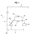
- Figure 1 is a schematic illustration of a generic embodiment of an entertainment device 10, which includes an entertainment unit 100 that is coupled to a support arm 300 that in turn is coupled to a base 500.
- the base 500 is coupled to the support arm to maintain the support arm 300 in an upright orientation and is movable between a first orientation in which the base 500 is coupleable to a vertical surface V and, a second orientation in which the base 500 can rest on a horizontal surface S.
- the entertainment unit 100 includes a light source 180 that projects on a surface opposite the light source.
- the opposite surface may be a wall or a ceiling depending upon the configuration of the entertainment device 10 (as will be described in detail below).
- a second light source 190 also projects on a surface spaced from the entertainment unit 100 (preferably a surface other than the surface illuminated by the first light sources 180.
- the light source 180, 190 may be illuminated by a single light bulb that illuminates each light source or multiple light bulbs.
- An article 170 may be suspended from the entertainment unit 100 via a detachable support 160.
- the detachable support may be removed from the entertainment unit (as indicated by the "X" in Figure 1 ).
- the entertainment device 10 When the base 500 is in its first orientation, the entertainment device 10 can be coupled to a vertical surface, such as a crib rail or a wall adjacent the crib, to function as a crib mobile. When the base 500 is in its second orientation, the entertainment device 10 can rest on a horizontal surface S to function as a lamp. Regardless of orientation, the entertainment unit 100 is configured to extend above a surface S, whether it be a crib mattress or a desk surface as described above.
- entertainment device 10 may include a remote actuator for actuation of the entertainment unit 100.
- FIG. 2 is a schematic illustration of the relationship of various components of entertainment device 10.
- convertible entertainment device 10 includes a user input block 20, a control block 30, and an output block 40.
- the control block controls the output of selected output, such as musical notes, sound effects, light patterns or combinations of musical notes and light patterns, from the output block 40.
- the functionality described with respect to Figure 2 is the same.
- Output block 40 includes output content 42, which includes audio content 42A, and video content 42B.
- Audio content 42A can include, for example, in either digital or analog form, musical tones (which can be combined to form musical compositions), speech (recorded or synthesized), or sounds (including recorded natural sounds, or electronically synthesized sounds).
- Video content can include, for example, in analog or digital form, still or video images, or simply control signals for activation of lamps or other light-emitting devices.
- the output content can be communicated to an infant for hearing, or viewing, by output generator 44, which can include an audio output generator 45, and a video output generator 46.
- Audio output generator 45 can include an audio signal generator 45A, which converts audio output content 42A into signals suitable for driving an audio transducer 45B, such as a speaker, for converting the signals into audible sound waves.
- Video output generator can include a video signal generator 46A, which converts video output content 42B into signals suitable for driving a video transducer 46B, such as a display screen or lights, for converting the signals into visible light waves.
- Video output generator can also include moving physical objects, such as miniature figures, to produce visual stimulus to the infant.
- the selection of the output content, and the performance attributes of the output generators, should be driven by the goal of generating output that is appealing or soothing to an infant. Audio pressure levels should be selected to calm, rather than startle, the infant. Audio content should be pleasing, comforting, and/or rhythmic or melodic.
- Control block 30 controls output block 40, selecting the output content to be output and activating the output generator 44 to operate on the selected output content.
- the operation of control block 30 can be governed by control logic 32, which can be, for example, computer software code.
- Control logic 32 can select content to be output repetitively or non-repetitively, and/or randomly or in fixed sequences.
- the video and audio output can be coordinated to enhance the pleasing effect.
- User input block 20 includes a mode selector 22, a local actuator 24, and a remote actuator 26, by which the user can provide input to control block 30 to influence the selection of output content and to initiate its output.
- Mode selector 22 allows the user to select from among output modes.
- Illustrative output modes include variations of combined video and audio output.
- the audio content 42A can include a set of musical tones and a set of sound effect segments
- the video content can include a selected sequence of illumination instructions for lamps.
- Control logic 32 includes sets of sequences in which the musical tones can be output to produce recognizable tunes.
- Various modes of light operation i.e., direction of light transmission
- a program can include a predetermined sequential output of the sets of tone sequences, producing a sequence of musical tunes. Lamps can be illuminated in response to a set of illumination instructions correlated with the playing of the tunes.
- the local and remote actuators 24 and 26 allow the user to input simple commands such as "start,” “stop,” or “repeat” via simple mechanisms such as mechanical contact switches.
- Local actuator 24 is physically proximate to the output block 40.
- remote actuator 26 includes a transmitter portion 27 that can be operated from a position physically remote from the output block 40, and a receiver portion 28 physically proximate to the output block 40.
- a command signal can be communicated between the transmitter portion and the receiver portion without a physical link, such as an electromagnetic signal (including infrared and radio frequency) or an acoustical (including ultrasonic), or with a physical link, such as an electrical signal carried by a conductor coupling the transmitter portion and the receiver portion.
- a wireless short-wave infrared system is used for communication of command signals.
- the transmitter 26 therefore includes an input button 27A (which the user can press to initiate a command signal), a command signal generator 27B activated by the button 27A, and an infrared emitting transducer (an LED) 27C.
- Receiver 28 includes an infrared receiving transducer (a photosensor) 28A and a processor 28B to interpret signals received by transducer 28A.
- User input block 20 further includes two feedback mechanisms for the user.
- the first is a beacon light 29A associated with, and physically proximate to, receiving transducer 28A.
- Beacon light 29A is illuminated (for example, in a flashing or intermittent fashion) when the system is active and ready to receive command signals from the remote actuator 26. This gives the user a visual cue to the system's active state, and further helps the user to locate the system in a darkened room.
- the second feedback mechanism is a remote signal light 29B associated with, and physically proximate to, transmitting transducer 27C.
- Signal light 29B is illuminated when the command signal generator 27B is generating command signals, to provide visual confirmation to the user that actuation of the input button 27A has resulted in the production of a command signal.
- a user places the output generator and the infant to be soothed within an operative range of one another.
- the user selects an output mode with mode select 22, and issues a "start" command via local actuator 24 or remote actuator 26.
- the control 30 receives the mode selection and the start command, selects the corresponding output content, and activates the output generator 44 to generate the selected output content.
- Use of the remote actuator to issue commands allows the user to be positioned remote from the infant, so that the soothing output can be generated while minimizing the risk that the user will disturb, or attract the attention of, the infant.
- Entertainment device 10 includes an entertainment unit 100 and a remote unit 200.
- the correspondence between the functional elements and the entertainment unit and remote units is illustrated in Figure 2 by phantom-lined boxes, identified as entertainment unit 100 and remote unit 200, drawn around the functional elements.
- Electrical schematic illustrations of the entertainment unit 100 and remote unit 200 are shown in Figures 12 and 14 , respectively.
- entertainment device 10 includes entertainment unit 100 coupled to a support arm 300, which is coupled to a base 500.
- the base 500 is movable between a first orientation in which the base is coupleable to a vertical surface, and a second orientation in which the base can rest on a horizontal surface.
- Figure 3 illustrates the entertainment device 10 in its first orientation such that the entertainment device 10 can be attached to the rail of a crib or a wall and function as a mobile or similar device.
- the components that comprise the mobile include detachable supports 160 and suspended articles 170 removably coupled to the ends of detachable supports 160. Suspended articles 170 may take many shapes such as cubes, spheres, animals, stars, etc.
- the entertainment device 10 can be reconfigured and placed in its second orientation by pivoting the base about pivot 315 such that the base 500 rests on a surface as illustrated in Figure 4 .
- entertainment unit housing 110 is composed of top and bottom housing halves 112, 114.
- Figure 5 illustrates a top portion of entertainment unit 100 and includes top housing half 112 having an opening defined in its sidewall for receiving a conduit of a motor housing 143 as will be described below with respect to Figure 6 .
- a dome 120 is inserted through the top housing and is coupled to a dome base 122.
- the dome or cover 120 is disposed above a light source (not visible in Figure 5 ) and may include a pattern printed thereon such that when the light source is illuminated, an image corresponding to the pattern is projected on a surface that is spaced from the entertainment unit 100.
- a drive assembly is included that rotates the dome base 122. Accordingly, a gear 131 is provided on dome base 122 that meshes with a gear train.
- FIG. 6 illustrates an exploded assembly view of the second portion of the entertainment unit 100.
- Lower housing half 114 is configured to be coupled to top housing half 112 to form the entertainment unit housing 110.
- a motor housing 140 that includes a conduit 141 for receiving wires and the like from the power source, as will be described below.
- a drive assembly 153 is housed within the motor housing 140 and includes a plurality of drive train 130 (with multiple gears), a first motor 150 and a second motor 155.
- the first motor 150 is configured to drive train 130 to rotate the dome base 122 as discussed above.
- the second motor 155 is configured to drive a rotating member 125 that is coupleable to lower housing 114 and is configured to drive the mobile when the entertainment device 10 is in the first configuration.
- Audio output generator 44 includes a speaker 191 (not visible in Figure 6 ), mounted in entertainment unit housing 110 behind a perforated speaker grill 181.
- the speaker is a 1" (2.5 cm) diameter driver, and is preferably driven to a sound pressure level of less than approximately 70 dB at 9.8" (24.5 cm) from the axial front of the speaker source.
- Detachable supports 160 are releasably coupled to rotating member 125. When the entertainment device 10 is in its first orientation, the detachable supports 160 are coupled to, and operate with, rotating member 125 to function as a mobile. When the entertainment device 10 is placed in its second orientation, the detachable supports 160 may be removed from rotating member 125 so as not to interfere with the light that is projecting downwardly on the surface opposite the entertainment unit 100.
- rotating member 125 includes slots 163 for receiving the detachable supports 160.
- Detachable supports 160 include a tab 162 that mate with slot 163.
- Figure 7 illustrates an alternative coupling technique, in which detachable supports 160' are attached to openings 163' in the rotating member 125 via a fastener 162', such as a screw.
- the detachable supports 160, 160' may take multiple configurations.
- the detachable supports 160, 160' may support an article 170 by a string as in a conventional mobile or the article 170 may be fixedly coupled to the end of the support post 160,160'.
- a film 116 may be included between a light source (not visible in Figure 6 ) coupled in a receptacle beneath lower housing 114 and the surface opposite entertainment unit 100 to produce an image on the opposing surface.
- the film 116 may not have any patterns printed thereon and may simply act as a cover for the light.
- a mounting frame 118 is coupled to rotating member 125 to maintain the position of the film 116.
- a lower dome 119 is coupled to the rotating member 125.
- the lower dome may be transparent or opaque and may or may not have patterns printed thereon.
- the film 116 may not be utilized and any image that is desired to be produced may be printed on the dome alone.
- Support arm 300 by which the housing can be mounted to a supporting structure such as an infant crib, is illustrated in greater detail.
- Support arm 300 is coupled to the entertainment unit housing 110 and includes a first portion 310 and a second portion 320.
- the first portion 310 includes a first side 311 and a second side 313 that couple together to form the first portion 310.
- the first portion 310 is provided with an opening 314 that is in registry with an opening in the second portion 320 such that together the first portion 310 and second portion 320 form support arm 300.
- the second portion 320 includes a first side 321 and a second side 323 that couple together around the opening 314.
- first portion 310 and second portion 320 may be a simple pivot connection such that when a knob 333 is loosened, the second portion 320 is able to pivot around pivot point 315 (see Figure 3 ).
- the connection between first portion 310 and second portion 320 may be a spring-loaded clutch such that no knob need be provided and simple application of force is enough to change the orientation of support arm 300.
- the lower portion 320 of support arm 300 may be provided with multiple sockets (not shown) for receiving first portion 310.
- one socket may be situated on a longitudinal axis of the lower portion, and a second socket may be perpendicular to the first socket such that the first portion may be friction fit in either of the alternative sockets to change the orientation of the support arm 300.
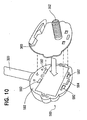
- the base 500 includes a base cover 510 that receives housing 573.
- Housing 573 includes a face 590 that defines openings or clip retainers 582.
- a mounting apparatus 550 for mounting the entertainment unit 100 on a fixed support, such as an upper rail R of an infant's crib is removably coupled to housing 573, such as, for example, by attachment clips 580 that mate with clip retainers 582.
- the mounting apparatus 550 includes a threaded mounting post 552 that is externally threaded and is configured to couple with mounting nut 554 that is internally threaded.
- Battery cover 576 covers a battery housing 575 and is flush with face 590 of housing 573.
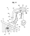
- the mounting apparatus 550 is able to couple to the face 590 via openings 582 in housing 573. Openings 582 could be configured as keyhole slots to mount on screws or nails protruding from a wall. There is also a release clip 584 that engages an opening in the mounting apparatus 550. As shown in Figure 11 , entertainment unit 100 can be mounted to rail R of a crib with the mounting apparatus 550 abutting the rail R at surface 560 when the mounting apparatus 550 is in place.
- Mounting apparatus 550 is configured to be easily removed from housing 573. When the entertainment device 10 is in its first configuration ( Figure 3 ), the mounting apparatus 550 is attached to face 590. When the mounting apparatus 550 is removed, the entertainment device can be reoriented such that face 590 abuts a supporting surface upon which the entertainment device 10 is to be situated.
- the audio signal generator 46a, video signal generator 45A, output content 42, and control block 30 are all implemented in the illustrated embodiment on controller 130, which is a model SN66012 available from Sonix Corporation.
- the audio content 42A is stored in digital form in a memory portion of controller 130.
- Audio content 42A includes sets of tone identifiers arranged in sequences corresponding to musical tunes. Seven such sets of tone identifiers are stored, allowing generation of ten musical tunes, such as Brahm's Lullaby, Twinkle Twinkle Little Star, Moonlight Sonata, Ocean Sounds, Night Time Sounds, etc.
- Controller 130 has the built-in capability to produce tones identified by the tone identifiers, and to drive speaker 191 to the desired sound pressure level.
- Local actuator 24 is implemented as entertainment unit input switch SW4 (illustrated in Figure 12 ), which is a momentary contact switch with button 161 mounted to the top 112 of entertainment unit housing 110 (see Figure 3 ), where it is readily accessible and easily activated.
- Mode selector 22 is implemented as mode select switches SW2 and SW3 (illustrated in Figure 12 ), which are momentary contact switches, with buttons 171, 172 positioned on the housing (see Figure 6 ), where they are readily accessible.
- the output lines from mode select switches SW2 and SW3 are coupled to controller 130 to provide signals to select the modes of operation for the entertainment device 10. As described in more detail below, there are multiple modes of operation.
- Remote actuator 26 is implemented as a short-wave infrared remote control system with components in the entertainment unit 100 and in the remote unit 200.
- the receiver 28 is implemented as remote receiver, with a photo sensor 822 (corresponding to receiving transducer 28A), which converts incident light in the short-wave infrared spectrum into electrical signals supplied to controller 130, which includes the function of command signal processor 28B to process the electrical signals received from photosensor 822 and determine whether the received IR signal is a command signal from remote transmitter 27.
- photosensor 822 is disposed on upper portion 112 of entertainment unit housing 110.
- the photosensor 822 has an effective angular field of view within which it can effectively detect incident IR signals.
- the field of view is approximately 90 degrees.
- entertainment unit power supply 183 which in the illustrated embodiment consists of batteries (four C-sized cells), which are housed in battery compartment 575 and accessed via battery cover 576. Wires are channeled through support arm 3400 and conduit 141 to drive the electronic components.
- Remote transmitter 27 of remote actuator 26 is implemented as an infrared transmitter, which is housed in remote unit 200.
- the remote unit 200 is similar to the remote unit described in U.S. Patent No. 6,116,983 , which is assigned to the assignee of the present invention.
- the infrared transmitter includes a remote controller 315 (corresponding to signal generator 27B) that generates an electronic signal that is communicated to transmission LED 840 (corresponding to transmission transducer 27C), which in turn generates an IR command signal.
- the remote controller 815 is a 14 stage binary counter model 74HC4060, which is a standard part commercially available from a variety of sources.
- controller 815 Operation of controller 815 is initiated by the user by actuating remote input switch SW1 (corresponding to input 27A), which in the illustrated embodiment is a momentary contact switch with a large circular remote button 821.
- the components of the infrared transmitter 810 are housed in remote housing 210 of remote unit 200.
- the remote unit 200 includes a remote unit housing 210, which is formed of a housing top 212, and a housing bottom (not visible in Figure 13 ).
- Remote unit 200 includes a U-shaped handle 230, which is pivotally mounted to housing 210 by handle pivot posts 234 that are trapped within mating semicircular cutouts in housing top 212 and housing bottom.
- the remote 200 can be carried or hung by the handle.
- Figure 13 shows the handle 230 in a deployed position. In the deployed position, there is sufficient space between the handle 230 and the remote housing 210 to accommodate a standard doorknob (not shown).
- the handle 230 can therefore be used to allow a parent to hang the remote unit on, for example, a doorknob at the entrance of an infant's bedroom so that the remote unit is accessible to the parent who wishes to produce output for the infant without disturbing or gaining the attention of the infant by his or her presence.
- An IR-transparent window (not shown) is also trapped between the housing top 212 and housing bottom.
- Transmission LED 840 is mounted in the housing behind the window.
- the remote unit uses batteries for a power supply.
- Remote button 821 is mounted in housing top 212.
- Indicator light 251 (corresponding to light 29B) is mounted in housing top 212 in front of button 821.
- a power supply (two AA batteries, in the disclosed embodiment) is also contained in a battery compartment of housing 210, and are accessed by a removable battery cover as would be apparent to those skilled in the art.
- the remote unit 200 produces IR control signals for activating the entertainment unit 100 at a remote distance, preferably at a minimum of 20' (6 m) from the remote receiver in normal household lighting conditions.
- the entertainment device 10 is activated by receiving the IR control signal from the remote unit 200 (the entertainment device can also be activated by pressing the manual activation button 161).
- the control signal transmitted from the remote unit 200 is detected by a remote receiver with a photo sensor for detecting short-wave IR signals modulated on a 37.9 kHz carrier frequency.
- Controller 130 receives input from the remote receiver 820 or local actuator button 161 and responds by causing the speaker 191 and/or lights to produce output depending on the mode selected by the user via mode selectors 171, 172 or the nature of the IR command received. If remote receiver 820 recognizes signals from photo sensor 822 as the command signal, and an output mode is selected, then the controller 130 will cause output to be produced.
- Controller 130 includes an internal timer by which it can monitor the time that has elapsed since a command signal was last received. If the elapsed time exceeds an established standby period, the receiver 820 portion of the remote control will shut down to conserve power. Once powered-down, the entertainment unit 100 will not produce output in response to a second control signal but will continue to respond to a user pressing the manual button 161. Pressing the manual button 161 will also power-on the remote receiver 820, making the entertainment unit 100 "remote ready.” The entertainment unit will also become “remote ready” if the user selects a new output mode, other than "off,” using the mode selector 171, 172. Once the entertainment unit 100 is "remote ready,” the user can thereafter activate the entertainment device via an IR command signal. There is no output generated when the mode selector switches 171, 172 are set to "off.”
- the various housing components, buttons, etc. are formed of plastic materials, but any other material suitable for use can be used.
- the disclosed audio generator has a fixed output volume, it is contemplated that a volume control could be added to permit the user to vary the output.
- the power supply is disclosed as batteries, but it is contemplated that alternative sources of power could be used, including household AC power. Moreover, it is contemplated that if AC power were used, the receiver portion of the remote could always be "remote ready" since there would not be the same level of concern with conserving power.
- the remotely controlled output uses a simple, one-function remote, however, other remotes with greater functionality are contemplated. For example, it is contemplated that remotes with buttons for remotely selecting output modes or remotes which transmit Radio-Frequency (RF) verses Infra Red (IR) signals.
- RF Radio-Frequency
- IR Infra Red
Landscapes
- Health & Medical Sciences (AREA)
- General Health & Medical Sciences (AREA)
- Pediatric Medicine (AREA)
- Toys (AREA)
- Window Of Vehicle (AREA)
- Permanent Field Magnets Of Synchronous Machinery (AREA)
- Adornments (AREA)
- Transition And Organic Metals Composition Catalysts For Addition Polymerization (AREA)
- Telephone Function (AREA)
Claims (13)
- Appareil de loisir transformable (10) comprenant :une unité de loisir (100) comportant une unité de projection (180, 190), une unité apaisante et un dispositif de sortie audio (45), ladite unité apaisante incluant un mobile disposé sensiblement en dessous de ladite unité de projection, ladite unité de projection (180, 190) incluant au moins un réceptacle de source de lumière ;une base (500) ; etun bras de support (300) comportant une première portion (310) et une seconde portion (320), la première portion (310) étant couplée à l'unité de loisir (100), la seconde portion (320) ayant un axe longitudinal, la seconde portion (320) étant couplée en pivotement à la base (500) de telle sorte que le bras de support peut être positionné dans une première configuration dans laquelle ladite base (500) est couplable à un support sensiblement vertical et une seconde configuration dans laquelle l'appareil (10) est autoportant sur une surface de support de telle sorte que l'axe longitudinal de la seconde portion (320) est sensiblement parallèle à la surface de support.
- Appareil (10) selon la revendication 1, incluant en outre un actionneur à distance (2b) pour initier le fonctionnement de ladite unité de loisir (100).
- Appareil (10) selon la revendication 1, dans lequel ladite unité de projection (180, 190) comprend :un couvercle (120) disposé au-dessus dudit au moins un réceptacle de source de lumière et sur lequel est formé un motif, de telle sorte que lorsqu'une source de lumière disposée dans ledit réceptacle est illuminée, une image correspondant audit motif est projetée sur une surface.
- Appareil (10) selon la revendication 3, dans lequel ledit couvercle (120) est rotatif autour dudit au moins un réceptacle de source de lumière.
- Appareil (10) selon la revendication 1, dans lequel ladite unité apaisante comprend :un élément de suspension (160) ; etun article (170) suspendu audit élément de suspension (160).
- Appareil (10) selon la revendication 1, dans lequel ladite unité apaisante comprend :un réceptacle de source de lumière ; etun couvercle (119) disposé sous ledit réceptacle de source de lumière.
- Appareil (10) selon la revendication 6, dans lequel ladite unité apaisante comprend en outre :un élément de suspension (160) ; etun article (170) suspendu audit élément de suspension (160).
- Appareil (10) selon la revendication 7, dans lequel ledit élément de suspension (160) est couplé de façon amovible à ladite unité de loisir (100).
- Appareil (10) selon la revendication 1, dans lequel ledit bras de support (300) comprend :un élément de support (300) couplé à ladite unité de loisir (100) ; etune base (500) couplée audit élément de support (300).
- Appareil (10) selon la revendication 9, dans lequel dans ladite première configuration, ledit axe longitudinal de la seconde portion (320) et ladite base (500) sont agencés de manière sensiblement linéaire et dans ladite seconde configuration, ledit axe longitudinal de la seconde portion (320) est sensiblement perpendiculaire à ladite base (500) et ladite base (500) met en prise la surface de support.
- Appareil (10) selon la revendication 9, dans lequel dans ladite première configuration, ladite base (500) est couplable à un berceau et ladite unité de loisir (100) est configurée pour être disposée au-dessus d'un nourrisson dans le berceau et dans ladite seconde configuration, ladite unité de loisir (100) est disposée sensiblement au-dessus de ladite base (500).
- Appareil (10) selon la revendication 1, comprenant en outre :un dispositif de montage couplable à ladite base (500) et audit support sensiblement vertical.
- Appareil (10) selon la revendication 1, comprenant en outre :un montant couplé à ladite base (500) pour coupler sélectivement ladite base (500) à un rail latéral d'un berceau lorsque ledit bras de support (300) est dans ladite première configuration ;une source de lumière montée dans ledit réceptacle de source de lumière et orientée pour illuminer la surface sur laquelle ladite base (500) est disposée lorsque ledit bras de support (300) est dans ladite seconde configuration ;un entraînement (153) monté dans ladite unité apaisante et couplé audit mobile pour faire tourner ledit mobile par rapport à ladite unité apaisante, ledit mobile incluant une pluralité de supports d'article détachables (160).
Applications Claiming Priority (2)
| Application Number | Priority Date | Filing Date | Title |
|---|---|---|---|
| US09/968,495 US7172486B2 (en) | 2001-10-02 | 2001-10-02 | Convertible entertainment device |
| EP02734599A EP1434634B1 (fr) | 2001-10-02 | 2002-05-31 | Dispositif de loisir transformable |
Related Parent Applications (2)
| Application Number | Title | Priority Date | Filing Date |
|---|---|---|---|
| EP02734599.0 Division | 2002-05-31 | ||
| EP02734599A Division EP1434634B1 (fr) | 2001-10-02 | 2002-05-31 | Dispositif de loisir transformable |
Publications (2)
| Publication Number | Publication Date |
|---|---|
| EP1952867A1 EP1952867A1 (fr) | 2008-08-06 |
| EP1952867B1 true EP1952867B1 (fr) | 2011-10-26 |
Family
ID=25514346
Family Applications (3)
| Application Number | Title | Priority Date | Filing Date |
|---|---|---|---|
| EP08009777A Expired - Lifetime EP1952867B1 (fr) | 2001-10-02 | 2002-05-31 | Dispositif de loisir transformable |
| EP02734599A Expired - Lifetime EP1434634B1 (fr) | 2001-10-02 | 2002-05-31 | Dispositif de loisir transformable |
| EP08009431A Expired - Lifetime EP1949946B1 (fr) | 2001-10-02 | 2002-05-31 | Dispositif de loisir transformable |
Family Applications After (2)
| Application Number | Title | Priority Date | Filing Date |
|---|---|---|---|
| EP02734599A Expired - Lifetime EP1434634B1 (fr) | 2001-10-02 | 2002-05-31 | Dispositif de loisir transformable |
| EP08009431A Expired - Lifetime EP1949946B1 (fr) | 2001-10-02 | 2002-05-31 | Dispositif de loisir transformable |
Country Status (8)
| Country | Link |
|---|---|
| US (1) | US7172486B2 (fr) |
| EP (3) | EP1952867B1 (fr) |
| AT (3) | ATE439898T1 (fr) |
| AU (1) | AU2002305755B2 (fr) |
| CA (1) | CA2462268C (fr) |
| DE (2) | DE60233452D1 (fr) |
| ES (1) | ES2311055T3 (fr) |
| WO (1) | WO2003028839A1 (fr) |
Families Citing this family (36)
| Publication number | Priority date | Publication date | Assignee | Title |
|---|---|---|---|---|
| US20030153240A1 (en) * | 2002-02-14 | 2003-08-14 | Dejule Aaron M. | Hanging mobile device with electronic display |
| US20040259070A1 (en) * | 2003-06-20 | 2004-12-23 | Goodstein Shelley R. | Child/infant play and entertainment devices including electronic displays |
| US20080139078A1 (en) * | 2004-10-22 | 2008-06-12 | Wang Tai Cheng Wang Eric | Apparatus for mounting a mobile to a crib |
| US7264534B2 (en) | 2004-12-30 | 2007-09-04 | Fertig Stubenfoll Design Group, L.L.C. | Toys with driven characters |
| US7476142B2 (en) * | 2005-03-02 | 2009-01-13 | Mattel, Inc. | Interactive entertainment apparatus |
| US20060264148A1 (en) * | 2005-05-22 | 2006-11-23 | Sejnowski Joseph P | Articulating mobile |
| US20060260663A1 (en) * | 2005-05-22 | 2006-11-23 | Sejnowski Joseph P | Projection mobile |
| US20080016624A1 (en) * | 2006-07-21 | 2008-01-24 | Kathy Osborn | Soothing devices |
| US20080020672A1 (en) * | 2006-07-21 | 2008-01-24 | Kathy Osborn | Programmable baby mobiles and baby soothing devices |
| US20080248714A1 (en) * | 2007-04-05 | 2008-10-09 | Whetstone Management Llc | Fan Attachment Arrangement |
| US7927171B2 (en) * | 2007-09-19 | 2011-04-19 | Mattel, Inc. | Infant entertainment device |
| IL186652A0 (en) * | 2007-10-15 | 2008-01-20 | Teraop Displays Ltd | A toy assembly |
| EP2249937B1 (fr) * | 2008-02-04 | 2013-05-29 | Tiny Love Ltd | Mobile |
| US8162517B2 (en) * | 2008-03-13 | 2012-04-24 | Lumisource, Inc. | Lamp |
| US8873767B2 (en) * | 2008-04-02 | 2014-10-28 | Rb Concepts Limited | Audio or audio/visual interactive entertainment system and switching device therefor |
| USD599861S1 (en) * | 2008-06-26 | 2009-09-08 | Tiny Love Ltd. | Mobile |
| US20100037440A1 (en) * | 2008-08-12 | 2010-02-18 | May Gerald A | Attachment System for Entertainment Device |
| US8771033B2 (en) * | 2009-06-17 | 2014-07-08 | Mattel, Inc. | Mobile for infant support structure |
| US20110230115A1 (en) * | 2010-03-22 | 2011-09-22 | Xiuqing Wang | Electronic remote control music mobile with built-in mp3 player, timer, colorful lights, remote baby monitor, and adjustable support arm |
| CN203329364U (zh) | 2010-09-01 | 2013-12-11 | 儿童二代公司 | 用于儿童附属物的连接装置 |
| USD695846S1 (en) * | 2011-02-02 | 2013-12-17 | Tiny Love Ltd. | Toy assembly |
| ES2436073B1 (es) * | 2011-02-03 | 2014-11-06 | Jose Daniel Martin Catoira | Dispositivo luminiscente con brillo de estrellas |
| US8978591B2 (en) * | 2012-06-27 | 2015-03-17 | Jesse G. Cogswell | Pet toy |
| DE202013103658U1 (de) | 2012-09-05 | 2013-10-22 | Tiny Love Ltd. | Konvertierbares Unterhaltungsmobile |
| JP6049405B2 (ja) * | 2012-11-05 | 2016-12-21 | 赤瀬産業株式会社 | 押し絵吊し雛 |
| US9510693B2 (en) | 2013-08-01 | 2016-12-06 | Mattel, Inc. | Bidirectional communication between an infant receiving system and a remote device |
| DE202015100700U1 (de) * | 2014-02-13 | 2015-05-28 | Tiny Love Ltd. | Kleinkinder-Spielvorrichtung |
| US9527000B1 (en) * | 2014-05-22 | 2016-12-27 | Playability Toys, LLC | Crib mobile and mounting structure therefor |
| US9585495B2 (en) * | 2014-09-05 | 2017-03-07 | Richard Gottsleben | Built-in mobile arm for a crib |
| US9533235B2 (en) * | 2014-09-16 | 2017-01-03 | Way-Hong Chen | Acousto-optical baby toy with a remote control monitoring function |
| USD744046S1 (en) * | 2014-09-16 | 2015-11-24 | Way-Hong Chen | Baby toy producing sound and light |
| US20170112295A1 (en) * | 2015-10-22 | 2017-04-27 | Prince Lionheart, Inc. | Contoured diaper changing pad including illumination |
| US9717999B2 (en) * | 2015-11-12 | 2017-08-01 | Mattel, Inc. | Infant entertainment apparatus and system with two-way projection |
| USD830472S1 (en) | 2016-08-04 | 2018-10-09 | Skip Hop, Inc. | Infant mobile |
| USD860327S1 (en) * | 2017-09-12 | 2019-09-17 | Kids Ii, Inc. | Children's toy |
| USD958897S1 (en) * | 2020-09-17 | 2022-07-26 | Kids2, Inc. | Modular toy bar |
Family Cites Families (43)
| Publication number | Priority date | Publication date | Assignee | Title |
|---|---|---|---|---|
| US1084375A (en) * | 1911-02-13 | 1914-01-13 | George B Swinehart | Portable electric lamp. |
| US1786459A (en) * | 1926-07-30 | 1930-12-30 | Simons Burdick | Baby-bottle holder |
| US1708047A (en) * | 1926-12-01 | 1929-04-09 | Harry J Bosworth Company | Light fixture |
| US1811618A (en) * | 1928-06-15 | 1931-06-23 | Miehle Printing Press & Mfg | Delivery mechanism |
| US1811818A (en) * | 1930-05-31 | 1931-06-23 | James C Davenport | Advertising apparatus |
| CH172498A (de) | 1934-02-16 | 1934-10-15 | Ammann Werner | Elektrische Stehlampe mit Befestigungsvorrichtung. |
| US2301661A (en) * | 1940-03-11 | 1942-11-10 | Arthur E Wiedenhoeft | Electric fixture |
| US2299683A (en) * | 1941-07-12 | 1942-10-20 | Curtis Lester | Trouble light |
| US2823477A (en) * | 1956-02-20 | 1958-02-18 | Henry F Willard | Lamp shade |
| US3109252A (en) * | 1960-06-24 | 1963-11-05 | Schweizer Milch Ges A G | Lamp shade structure |
| US3628005A (en) | 1970-02-27 | 1971-12-14 | Esb Inc | Lantern |
| US3927482A (en) * | 1974-07-01 | 1975-12-23 | Dolly Toy Co | Decorative nursery accessory |
| US3919795A (en) | 1974-09-23 | 1975-11-18 | Horne Jinivisian Sydney C Van | Motorized mobile |
| US4147344A (en) * | 1977-08-19 | 1979-04-03 | Lee Arthur L | Tensioning type physical therapeutical treatment device |
| GB2019229B (en) | 1978-04-27 | 1982-08-04 | Sanyo Onkyo Seiki Co Ltd | Toys |
| US4207696A (en) * | 1978-07-31 | 1980-06-17 | Greenberg Lawrence J | Sound activated mobile |
| US4214808A (en) * | 1978-10-25 | 1980-07-29 | Hampson Edward A | Kaleidoscopic mobile |
| US4285028A (en) * | 1979-06-15 | 1981-08-18 | Glen Sundin | Bedroom lamp with clock operated lamp switch |
| US4573654A (en) | 1983-06-29 | 1986-03-04 | Meritus Industries, Inc. | Mounting structure for a crib toy |
| US4756109A (en) | 1983-08-30 | 1988-07-12 | Dolly, Inc. | Nursery mobile |
| US4640034A (en) | 1985-05-14 | 1987-02-03 | Barry Zisholtz | Mobile for infants |
| US4939582A (en) | 1987-04-06 | 1990-07-03 | Holdredge Terry K | Convertible visual display device |
| DE3718369A1 (de) | 1987-06-02 | 1988-12-15 | Schirnecker Hans Ludwig | Drehschattenleuchte |
| US4858079A (en) | 1987-11-16 | 1989-08-15 | Tomy Kogyo Co., Inc. | Light projecting toy musical box |
| US4911489A (en) * | 1989-02-01 | 1990-03-27 | A. L. Hansen Manufacturing Company | T-handle latch |
| US4984380A (en) * | 1989-07-17 | 1991-01-15 | Anderson Rodney D | Body-motion activated crib mobile |
| US5029047A (en) | 1990-05-24 | 1991-07-02 | Kachel Bruce S | Lighted fiber optic mobile |
| JPH0422995U (fr) * | 1990-06-16 | 1992-02-25 | ||
| US5352145A (en) * | 1990-12-11 | 1994-10-04 | Gund, Inc. | Child's mobile and improved element clamp therefor |
| US5192041A (en) | 1991-06-17 | 1993-03-09 | Bryant Sheree M | Baby bottle holder |
| US5324224A (en) | 1991-12-09 | 1994-06-28 | Anderson Richard H | Spherical construction toy and light apparatus |
| US5370570A (en) * | 1993-04-27 | 1994-12-06 | Harris; Steven O. | Portable mobile |
| US5672088A (en) | 1995-02-16 | 1997-09-30 | Kids Ii, Inc. | Infant toy with universal mounting means |
| GB2300252A (en) | 1995-04-24 | 1996-10-30 | Yu Chai Chi | Decorative lamp assembly adapted to provide silhouetting effects |
| US5803786A (en) * | 1996-09-30 | 1998-09-08 | Mccormick; Kathy | Continuous play musical mobile |
| US5931716A (en) | 1997-06-09 | 1999-08-03 | Hopkins; Lloyd M. | Illuminated flying toy |
| US5988828A (en) | 1997-07-18 | 1999-11-23 | Milwaukee Electric Tool Corporation | Portable light incorporating a multi-position hook |
| US6016038A (en) * | 1997-08-26 | 2000-01-18 | Color Kinetics, Inc. | Multicolored LED lighting method and apparatus |
| US5951360A (en) * | 1998-03-20 | 1999-09-14 | Fearon; Beatrice B. | Infant mobile with compact disc/cassette player apparatus |
| US6079855A (en) * | 1998-04-23 | 2000-06-27 | Azeredo; Ruth Ann | Detachable decorative system for lamp shades |
| US6113455A (en) * | 1999-03-18 | 2000-09-05 | Whelan; Kim | Versatile crib mounted mobile |
| US6236622B1 (en) * | 1999-05-01 | 2001-05-22 | Verilux, Inc. | Lamp and alarm clock with gradually increasing light or sounds |
| US6447362B2 (en) * | 2000-05-23 | 2002-09-10 | Lisa Khamphilavong | Rotating musical remote control mobile device with detachable toys |
-
2001
- 2001-10-02 US US09/968,495 patent/US7172486B2/en not_active Expired - Lifetime
-
2002
- 2002-05-31 CA CA2462268A patent/CA2462268C/fr not_active Expired - Fee Related
- 2002-05-31 AU AU2002305755A patent/AU2002305755B2/en not_active Ceased
- 2002-05-31 DE DE60233452T patent/DE60233452D1/de not_active Expired - Lifetime
- 2002-05-31 ES ES02734599T patent/ES2311055T3/es not_active Expired - Lifetime
- 2002-05-31 EP EP08009777A patent/EP1952867B1/fr not_active Expired - Lifetime
- 2002-05-31 AT AT08009431T patent/ATE439898T1/de not_active IP Right Cessation
- 2002-05-31 EP EP02734599A patent/EP1434634B1/fr not_active Expired - Lifetime
- 2002-05-31 WO PCT/US2002/017100 patent/WO2003028839A1/fr not_active Ceased
- 2002-05-31 EP EP08009431A patent/EP1949946B1/fr not_active Expired - Lifetime
- 2002-05-31 AT AT02734599T patent/ATE400340T1/de not_active IP Right Cessation
- 2002-05-31 DE DE60227545T patent/DE60227545D1/de not_active Expired - Lifetime
- 2002-05-31 AT AT08009777T patent/ATE530235T1/de not_active IP Right Cessation
Also Published As
| Publication number | Publication date |
|---|---|
| WO2003028839A1 (fr) | 2003-04-10 |
| US7172486B2 (en) | 2007-02-06 |
| ATE530235T1 (de) | 2011-11-15 |
| ATE439898T1 (de) | 2009-09-15 |
| CA2462268A1 (fr) | 2003-04-10 |
| EP1434634A1 (fr) | 2004-07-07 |
| WO2003028839A9 (fr) | 2003-09-04 |
| EP1952867A1 (fr) | 2008-08-06 |
| US20030064818A1 (en) | 2003-04-03 |
| CA2462268C (fr) | 2010-11-02 |
| EP1949946A1 (fr) | 2008-07-30 |
| ES2311055T3 (es) | 2009-02-01 |
| ATE400340T1 (de) | 2008-07-15 |
| AU2002305755B2 (en) | 2007-11-08 |
| EP1434634B1 (fr) | 2008-07-09 |
| DE60227545D1 (de) | 2008-08-21 |
| EP1949946B1 (fr) | 2009-08-19 |
| DE60233452D1 (de) | 2009-10-01 |
Similar Documents
| Publication | Publication Date | Title |
|---|---|---|
| EP1952867B1 (fr) | Dispositif de loisir transformable | |
| AU2002305755A1 (en) | Convertible entertainment device | |
| CA2300180C (fr) | Jouet telecommande pour lit de bebe | |
| US6759961B2 (en) | Two-way communication baby monitor with a soothing unit | |
| US6769952B1 (en) | Mobile and method of using the same | |
| US5307051A (en) | Night light apparatus and method for altering the environment of a room | |
| US6491516B1 (en) | Active Hanukkah candelabrum | |
| US20010003695A1 (en) | Convertible child's toy | |
| US20060199468A1 (en) | Interactive entertainment apparatus | |
| CN203634830U (zh) | 可转换娱乐悬吊玩具 | |
| US20080020672A1 (en) | Programmable baby mobiles and baby soothing devices | |
| US6544096B1 (en) | Toy lantern | |
| WO2017070870A1 (fr) | Coussin de jeu d'interaction acousto-optique de commande multimode pour système de détection et de logique d'apprentissage pour enfants | |
| US20140308873A1 (en) | Sensory stimulation device | |
| US20050148278A1 (en) | Amusement device for an infant crib or the like | |
| US20030171065A1 (en) | Infant mobile having multiple activation modes, including a kick-bar activation mode and a remote activation mode | |
| US20060260663A1 (en) | Projection mobile | |
| HK1028573B (en) | Remotely controlled crib toy | |
| CN216877837U (zh) | 一种多功能玩具 | |
| EP4368269B1 (fr) | Dispositif d'animation par éclairage | |
| JP2539407Y2 (ja) | 遊戯おもちゃ | |
| JPH0286002A (ja) | 可動ライト装置 |
Legal Events
| Date | Code | Title | Description |
|---|---|---|---|
| PUAI | Public reference made under article 153(3) epc to a published international application that has entered the european phase |
Free format text: ORIGINAL CODE: 0009012 |
|
| 17P | Request for examination filed |
Effective date: 20080606 |
|
| AC | Divisional application: reference to earlier application |
Ref document number: 1434634 Country of ref document: EP Kind code of ref document: P |
|
| AK | Designated contracting states |
Kind code of ref document: A1 Designated state(s): AT BE CH CY DE DK ES FI FR GB GR IE IT LI LU MC NL PT SE TR |
|
| AKX | Designation fees paid |
Designated state(s): AT BE CH CY DE DK ES FI FR GB GR IE IT LI LU MC NL PT SE TR |
|
| GRAP | Despatch of communication of intention to grant a patent |
Free format text: ORIGINAL CODE: EPIDOSNIGR1 |
|
| GRAS | Grant fee paid |
Free format text: ORIGINAL CODE: EPIDOSNIGR3 |
|
| RIN1 | Information on inventor provided before grant (corrected) |
Inventor name: JOURDIAN, ROBERT W. Inventor name: DROSENDAHL, CHRISTINE ANN Inventor name: MAGGIORE, ALBERT Inventor name: FRANKEL, SETH |
|
| GRAA | (expected) grant |
Free format text: ORIGINAL CODE: 0009210 |
|
| AC | Divisional application: reference to earlier application |
Ref document number: 1434634 Country of ref document: EP Kind code of ref document: P |
|
| AK | Designated contracting states |
Kind code of ref document: B1 Designated state(s): AT BE CH CY DE DK ES FI FR GB GR IE IT LI LU MC NL PT SE TR |
|
| REG | Reference to a national code |
Ref country code: GB Ref legal event code: FG4D |
|
| REG | Reference to a national code |
Ref country code: CH Ref legal event code: EP |
|
| REG | Reference to a national code |
Ref country code: IE Ref legal event code: FG4D |
|
| REG | Reference to a national code |
Ref country code: DE Ref legal event code: R096 Ref document number: 60241428 Country of ref document: DE Effective date: 20120119 |
|
| REG | Reference to a national code |
Ref country code: NL Ref legal event code: VDEP Effective date: 20111026 |
|
| REG | Reference to a national code |
Ref country code: AT Ref legal event code: MK05 Ref document number: 530235 Country of ref document: AT Kind code of ref document: T Effective date: 20111026 |
|
| PG25 | Lapsed in a contracting state [announced via postgrant information from national office to epo] |
Ref country code: BE Free format text: LAPSE BECAUSE OF FAILURE TO SUBMIT A TRANSLATION OF THE DESCRIPTION OR TO PAY THE FEE WITHIN THE PRESCRIBED TIME-LIMIT Effective date: 20111026 |
|
| PG25 | Lapsed in a contracting state [announced via postgrant information from national office to epo] |
Ref country code: PT Free format text: LAPSE BECAUSE OF FAILURE TO SUBMIT A TRANSLATION OF THE DESCRIPTION OR TO PAY THE FEE WITHIN THE PRESCRIBED TIME-LIMIT Effective date: 20120227 Ref country code: GR Free format text: LAPSE BECAUSE OF FAILURE TO SUBMIT A TRANSLATION OF THE DESCRIPTION OR TO PAY THE FEE WITHIN THE PRESCRIBED TIME-LIMIT Effective date: 20120127 Ref country code: NL Free format text: LAPSE BECAUSE OF FAILURE TO SUBMIT A TRANSLATION OF THE DESCRIPTION OR TO PAY THE FEE WITHIN THE PRESCRIBED TIME-LIMIT Effective date: 20111026 Ref country code: SE Free format text: LAPSE BECAUSE OF FAILURE TO SUBMIT A TRANSLATION OF THE DESCRIPTION OR TO PAY THE FEE WITHIN THE PRESCRIBED TIME-LIMIT Effective date: 20111026 |
|
| PG25 | Lapsed in a contracting state [announced via postgrant information from national office to epo] |
Ref country code: CY Free format text: LAPSE BECAUSE OF FAILURE TO SUBMIT A TRANSLATION OF THE DESCRIPTION OR TO PAY THE FEE WITHIN THE PRESCRIBED TIME-LIMIT Effective date: 20111026 |
|
| PG25 | Lapsed in a contracting state [announced via postgrant information from national office to epo] |
Ref country code: DK Free format text: LAPSE BECAUSE OF FAILURE TO SUBMIT A TRANSLATION OF THE DESCRIPTION OR TO PAY THE FEE WITHIN THE PRESCRIBED TIME-LIMIT Effective date: 20111026 |
|
| PG25 | Lapsed in a contracting state [announced via postgrant information from national office to epo] |
Ref country code: IT Free format text: LAPSE BECAUSE OF FAILURE TO SUBMIT A TRANSLATION OF THE DESCRIPTION OR TO PAY THE FEE WITHIN THE PRESCRIBED TIME-LIMIT Effective date: 20111026 |
|
| PLBE | No opposition filed within time limit |
Free format text: ORIGINAL CODE: 0009261 |
|
| STAA | Information on the status of an ep patent application or granted ep patent |
Free format text: STATUS: NO OPPOSITION FILED WITHIN TIME LIMIT |
|
| 26N | No opposition filed |
Effective date: 20120727 |
|
| REG | Reference to a national code |
Ref country code: DE Ref legal event code: R097 Ref document number: 60241428 Country of ref document: DE Effective date: 20120727 |
|
| PG25 | Lapsed in a contracting state [announced via postgrant information from national office to epo] |
Ref country code: MC Free format text: LAPSE BECAUSE OF NON-PAYMENT OF DUE FEES Effective date: 20120531 |
|
| REG | Reference to a national code |
Ref country code: CH Ref legal event code: PL |
|
| PG25 | Lapsed in a contracting state [announced via postgrant information from national office to epo] |
Ref country code: LI Free format text: LAPSE BECAUSE OF NON-PAYMENT OF DUE FEES Effective date: 20120531 Ref country code: AT Free format text: LAPSE BECAUSE OF FAILURE TO SUBMIT A TRANSLATION OF THE DESCRIPTION OR TO PAY THE FEE WITHIN THE PRESCRIBED TIME-LIMIT Effective date: 20111026 Ref country code: CH Free format text: LAPSE BECAUSE OF NON-PAYMENT OF DUE FEES Effective date: 20120531 |
|
| REG | Reference to a national code |
Ref country code: IE Ref legal event code: MM4A |
|
| REG | Reference to a national code |
Ref country code: FR Ref legal event code: ST Effective date: 20130131 |
|
| PG25 | Lapsed in a contracting state [announced via postgrant information from national office to epo] |
Ref country code: FR Free format text: LAPSE BECAUSE OF NON-PAYMENT OF DUE FEES Effective date: 20120531 Ref country code: ES Free format text: LAPSE BECAUSE OF FAILURE TO SUBMIT A TRANSLATION OF THE DESCRIPTION OR TO PAY THE FEE WITHIN THE PRESCRIBED TIME-LIMIT Effective date: 20120206 Ref country code: IE Free format text: LAPSE BECAUSE OF NON-PAYMENT OF DUE FEES Effective date: 20120531 |
|
| PG25 | Lapsed in a contracting state [announced via postgrant information from national office to epo] |
Ref country code: FI Free format text: LAPSE BECAUSE OF FAILURE TO SUBMIT A TRANSLATION OF THE DESCRIPTION OR TO PAY THE FEE WITHIN THE PRESCRIBED TIME-LIMIT Effective date: 20111026 |
|
| PG25 | Lapsed in a contracting state [announced via postgrant information from national office to epo] |
Ref country code: TR Free format text: LAPSE BECAUSE OF FAILURE TO SUBMIT A TRANSLATION OF THE DESCRIPTION OR TO PAY THE FEE WITHIN THE PRESCRIBED TIME-LIMIT Effective date: 20111026 |
|
| PG25 | Lapsed in a contracting state [announced via postgrant information from national office to epo] |
Ref country code: LU Free format text: LAPSE BECAUSE OF NON-PAYMENT OF DUE FEES Effective date: 20120531 |
|
| PGFP | Annual fee paid to national office [announced via postgrant information from national office to epo] |
Ref country code: GB Payment date: 20140527 Year of fee payment: 13 |
|
| PGFP | Annual fee paid to national office [announced via postgrant information from national office to epo] |
Ref country code: DE Payment date: 20140529 Year of fee payment: 13 |
|
| REG | Reference to a national code |
Ref country code: DE Ref legal event code: R119 Ref document number: 60241428 Country of ref document: DE |
|
| GBPC | Gb: european patent ceased through non-payment of renewal fee |
Effective date: 20150531 |
|
| PG25 | Lapsed in a contracting state [announced via postgrant information from national office to epo] |
Ref country code: DE Free format text: LAPSE BECAUSE OF NON-PAYMENT OF DUE FEES Effective date: 20151201 Ref country code: GB Free format text: LAPSE BECAUSE OF NON-PAYMENT OF DUE FEES Effective date: 20150531 |