EP1952870A2 - Frame and cartridge filter - Google Patents
Frame and cartridge filter Download PDFInfo
- Publication number
- EP1952870A2 EP1952870A2 EP07019822A EP07019822A EP1952870A2 EP 1952870 A2 EP1952870 A2 EP 1952870A2 EP 07019822 A EP07019822 A EP 07019822A EP 07019822 A EP07019822 A EP 07019822A EP 1952870 A2 EP1952870 A2 EP 1952870A2
- Authority
- EP
- European Patent Office
- Prior art keywords
- wall elements
- frame
- wall
- frame according
- filter
- Prior art date
- Legal status (The legal status is an assumption and is not a legal conclusion. Google has not performed a legal analysis and makes no representation as to the accuracy of the status listed.)
- Withdrawn
Links
Images



Classifications
-
- B—PERFORMING OPERATIONS; TRANSPORTING
- B01—PHYSICAL OR CHEMICAL PROCESSES OR APPARATUS IN GENERAL
- B01D—SEPARATION
- B01D46/00—Filters or filtering processes specially modified for separating dispersed particles from gases or vapours
- B01D46/0002—Casings; Housings; Frame constructions
- B01D46/0005—Mounting of filtering elements within casings, housings or frames
-
- B—PERFORMING OPERATIONS; TRANSPORTING
- B01—PHYSICAL OR CHEMICAL PROCESSES OR APPARATUS IN GENERAL
- B01D—SEPARATION
- B01D46/00—Filters or filtering processes specially modified for separating dispersed particles from gases or vapours
- B01D46/0002—Casings; Housings; Frame constructions
- B01D46/0013—Modules
-
- B—PERFORMING OPERATIONS; TRANSPORTING
- B01—PHYSICAL OR CHEMICAL PROCESSES OR APPARATUS IN GENERAL
- B01D—SEPARATION
- B01D2265/00—Casings, housings or mounting for filters specially adapted for separating dispersed particles from gases or vapours
- B01D2265/02—Non-permanent measures for connecting different parts of the filter
- B01D2265/024—Mounting aids
- B01D2265/025—Mounting aids making use of ramps or cams
-
- B—PERFORMING OPERATIONS; TRANSPORTING
- B01—PHYSICAL OR CHEMICAL PROCESSES OR APPARATUS IN GENERAL
- B01D—SEPARATION
- B01D2265/00—Casings, housings or mounting for filters specially adapted for separating dispersed particles from gases or vapours
- B01D2265/02—Non-permanent measures for connecting different parts of the filter
- B01D2265/028—Snap, latch or clip connecting means
Definitions
- the invention relates to a frame for receiving a filter element, comprising four wall elements, which abut against each other at mounting edges and form a circumferential wall.
- the invention further relates to a cassette filter comprising such a frame.
- the generic frame are not inexpensive to produce, since they consist of a variety of individual components that must be made in a complex manner.
- the invention is therefore an object of the invention to provide a frame for receiving a Filterelemts, which is easy to install after inexpensive production.
- each two wall elements are identical.
- two identical wall elements which are configured at least in the region of their mounting edges complementary to two other identical wall elements, are easy to install, as can be dispensed with further components for fixing the wall elements.
- a frame is specified, which is easy to install after inexpensive production.
- Means for fixing and connecting the wall elements could be formed on the mounting edges.
- This specific embodiment makes it possible to produce a frame which consists exclusively of four components, namely the wall elements.
- the means for fixing and connecting the wall elements could be integrated in the mounting edges or be shaped out of these.
- This specific embodiment allows a compact construction of the frame and a captive assignment of the means for fixing and connection to the wall elements.
- Means for locking the wall elements could be formed on the mounting edges. Means for locking allow a detachable connection of the wall elements. Furthermore, means for locking the wall elements allow rapid fixation and connection of the wall elements. By providing means for locking on the wall elements of the frame can be mounted very quickly.
- Each two wall elements could have locking tongues and two wall elements each recordings for the locking tongues.
- the formation of locking tongues allow engagement in the recordings and thus a firm connection of the wall elements together.
- the formation of locking tongues is also advantageous because they can be relatively easily deformed and bent to solve the wall elements from each other or to assemble one another.
- the locking tongues are provided which have a passage in which a survey of a wall element can engage.
- the passage may be circular and the receptacle as a circular elevation, which engages in the passage.
- This concrete embodiment is particularly advantageous in terms of manufacturing because round passages can be easily mounted in an injection molding process,
- insertion bevels could be arranged on the wall elements.
- the arrangement of chamfers allows easy installation of the frame in a frame housing, in particular in a so-called filter house.
- the frame can be introduced by means of the insertion bevels without tilting in a receptacle of a filter house.
- the insertion bevels could be arranged on the wall elements such that they form a circumferential ramp or phase.
- the wall elements could be associated with reinforcing ribs.
- the arrangement of reinforcing ribs makes it possible to produce the wall elements with a thin wall thickness. This material can be saved. Against this background, it is conceivable that the reinforcing ribs are turned towards the inside of the frame. This ensures that the outer wall of the frame is smooth. This embodiment allows a virtually resistance-free insertion of the frame in a filter house.
- mounting handles could be arranged on at least two wall elements.
- the design of mounting handles allows easy assembly and disassembly of the frame in the filter house, as the person mounting can grab and move the frame on the mounting handles.
- At least two wall elements could identify retaining webs.
- the retaining webs prevent polyurethane applied to the wall elements from flowing out of the assembled frame.
- other materials are conceivable which can connect a filter element with the wall elements.
- the wall elements could have protruding strips from the wall.
- This specific embodiment allows a flange-like design of a head frame, which allows a system of the frame on the wall of a filter house.
- the strips could have smooth surfaces on which seals are attached, which come to the filter house to the plant.
- the seals cause a sealing contact of the frame on the housing of the filter house.
- the seals could be sprayed onto the surfaces to allow rapid manufacture of the seals.
- the strips could have a U-profile, be hollow and have concave stabilizing webs.
- the hollow training allows to save weight.
- the provision of stabilizer bars prevents the bars from being compressed and thereby damaged.
- the concave formation of the stabilizing webs causes them to be offset inwards. Due to this specific embodiment, a person sitting can not injure himself at the stabilizing webs. The risk of injury is further prevented by their concave, namely flattened training.
- the displacement of the stabilizing webs inwardly also causes that when mounting the frame screws, springs or the like almost can not abut the Stabilisierurst webs. As a result, the mounting of the frame in the filter house is greatly facilitated.
- the strips could form a head frame.
- the head frame can cause the installation of the frame in a filter house.
- the wall elements could be designed as injection-molded parts. This specific embodiment allows a fast and cost-effective production of the wall elements.
- a cartridge filter could include a frame described herein and a filter element held by the frame.
- a cassette filter can be used in a filter house to clean air from airborne particles.
- the cartridge filter could include a pleat pack of zig-zag folded filter paper or nonwoven fabric. The folding increases the effective filter area.
- Fig. 1 shows a frame for receiving a filter element comprising four wall elements 1, 2, which abut one another at mounting edges 3, 4 and form a circumferential wall 5.
- Each two wall elements 1, 2 are identically formed.
- the wall elements 1, 2 are formed in the region of the mounting edges 3, 4 complementary to each other and connected to each other by latching.
- Each two wall elements 1 have locking tongues 6 and two wall elements 2 each have receptacles 7 for the locking tongues.
- the wall elements 1, 2 are assigned internal reinforcing ribs 9. This ensures that the wall 5, which is directed outwards, just designed.
- mounting handles 10 which serve the assembly and disassembly of the frame in a filter house.
- the wall elements 1, 2 have protruding from the wall 5 strips 12.
- the strips 12 form a head frame, which is configured in a flange and allows a system of the frame on the wall of a filter house, not shown.
- the wall elements are designed as injection molded parts. In the interior of the frame, a not shown filter element 14 can be inserted.
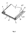
- Fig. 2 shows one of the wall elements 1, in the frame according to Fig. 1 are installed.
- the wall element 1 has receptacles 7 for locking tongues, not shown.
- an insertion bevel 8 is arranged, which complements with the other wall elements 1, 2 to a circumferential ramp.
- the wall element 1 has a retaining web 11 which prevents polyurethane from being able to escape from the frame in the assembled state.
- the wall element 1 has a protruding from the wall 5 bar 12 which shows a U-profile.
- the bar 12 is hollow and concave, inwardly offset stabilizing webs 13. These stabilizing bars 13 prevent the bar 12 from being compressed.
- the wall element 1 is designed as an injection molded part.
- seals may be attached on the flat surfaces 12a and 12b of the bar 12 seals.
- the seals can be sprayed on.
- the surface 12b faces the surface 12a.
- Fig. 3 shows one of the wall elements 2, in accordance with Fig. 1 are installed.
- the wall element 2 has latching tongues 6, which can engage in receptacles 7 of a wall element 1.
- One of the locking tongues 6 has a round passage in which a round elevation 7 of the wall element 1 according to Fig. 2 can intervene.
- Another latching tongue 6 is designed as a latching hook, which can engage behind a web, not shown, in the wall element 1.
- the wall element 2 has an insertion bevel 8, which complements the insertion bevels 8 of the wall elements 1 and 2 to form a circumferential ramp.
- the wall element 2 shows reinforcing ribs 9.
- the wall element 1 according to Fig. 2 are also associated with reinforcing ribs 9, but which are not visible because Fig. 2 the flat wall of the wall element 1 shows.
- the wall element 2 has mounting handles 10, which are designed quarter-circle. In the locked state of the quarter-circular mounting handle 10 forms a rounded corner portion of the frame.
- the Wall element 2 has a protruding from the wall 5 bar 12, which can form a head frame.
- the wall element 2 is designed as an injection molded part.
- Fig. 4 shows in an explanatory view the individual manufacturing steps for producing a cassette filter comprising a filter element 14.
- the method comprises the following production steps:
- Providing a wall element 1 and filling its inner wall with polyurethane Placing the filter element 14 on the wall element 1. placing a further wall element 1 on the filter element 14, wherein the further wall element 1 is also filled with polyurethane. The arranged on the filter element 14 wall elements 1 are locked with a wall element 2, which is also filled with polyurethane. Finally, another wall element 2 is locked to the wall elements 1. Also, the last wall element 2 is filled with polyurethane.
- the method described here allows the manufacture of a cassette filter having a frame described herein and a filter element 14 held by the frame.
Landscapes
- Chemical & Material Sciences (AREA)
- Chemical Kinetics & Catalysis (AREA)
- Filtering Of Dispersed Particles In Gases (AREA)
Abstract
Ein Rahmen zur Aufnahme eines Filterelements, umfassend vier Wandelemente (1, 2), die an Mbntagekanten (3, 4) aneinanderliegen und eine umlaufende Wandung (5) ausbilden, ist im Hinblick auf die Aufgabe, einen Rahmen zur Aufnahme eines Filterelemts zu schaffen, welcher nach kostengünstiger Herstellung problemlos montierbar ist, dadurch gekennzeichnet, dass jeweils zwei Wandelemente (1, 2) identisch ausgebildet sind. Des weiteren ist ein Kassettenfilter angegeben.

Description
Die Erfindung betrifft einen Rahmen zur Aufnahme eines Filterelements, umfassend vier Wandelemente, die an Montagekanten aneinanderliegen und eine umlaufende Wandung ausbilden. Die Erfindung betrifft des weiteren einen Kassettenfilter, der einen solchen Rahmen umfasst.The invention relates to a frame for receiving a filter element, comprising four wall elements, which abut against each other at mounting edges and form a circumferential wall. The invention further relates to a cassette filter comprising such a frame.
Kassettenfilter der eingangs genannten Art sind aus dem Stand der Technik bereits bekannt. Beispielsweise zeigt die
Die gattungsbildenden Rahmen sind nicht kostengünstig herstellbar, da sie aus einer Vielzahl von Einzelbauteilen bestehen, die in aufwendiger Weise gefertigt werden müssen.The generic frame are not inexpensive to produce, since they consist of a variety of individual components that must be made in a complex manner.
Der Erfindung liegt daher die Aufgabe zugrunde, einen Rahmen zur Aufnahme eines Filterelemts zu schaffen, welcher nach kostengünstiger Herstellung problemlos montierbar ist.The invention is therefore an object of the invention to provide a frame for receiving a Filterelemts, which is easy to install after inexpensive production.
Erfindungsgemäß wird die voranstehende Aufgabe durch einen Rahmen mit den Merkmalen des Patentanspruchs 1 gelöst, Danach sind jeweils zwei Wandelemente identisch ausgebildet.According to the invention the above object is achieved by a frame having the features of
Erfindungsgemäß ist erkannt worden, dass die Ausbildung jeweils zweier identischer Wandelemente sowohl die Fertigung der Wandelemente als auch deren Lagerhaltung erheblich vereinfacht. Insbesondere ist erkannt worden, dass zwei jeweils identische Wandelemente, die zumindest im Bereich ihrer Montagekanten komplementär zu zwei weiteren identischen Wandelementen ausgestaltet sind, problemlos montierbar sind, da auf weitere Bauteile zur Fixierung der Wandelemente verzichtet werden kann. Insoweit ist ein Rahmen angegeben, der nach kostengünstiger Herstellung problemlos montierbar ist.According to the invention, it has been recognized that the formation of two identical wall elements in each case considerably simplifies both the manufacture of the wall elements and their storage. In particular, it has been recognized that two identical wall elements, which are configured at least in the region of their mounting edges complementary to two other identical wall elements, are easy to install, as can be dispensed with further components for fixing the wall elements. In that regard, a frame is specified, which is easy to install after inexpensive production.
Folglich ist die eingangs genannte Aufgabe gelöst.Consequently, the object mentioned above is achieved.
An den Montagekanten könnten Mittel zur Fixierung und Verbindung der Wandelemente ausgebildet sein. Diese konkrete Ausgestaltung erlaubt es, einen Rahmen zu fertigen, der ausschließlich aus vier Bauteilen, nämlich den Wandelementen, besteht. Die Mittel zur Fixierung und Verbindung der Wandelemente könnten in den Montagekanten integriert sein beziehungsweise aus diesen herausgeformt sein. Diese konkrete Ausgestaltung erlaubt einen kompakten Aufbau des Rahmens und eine verliersichere Zuordnung der Mittel zur Fixierung und Verbindung zu den Wandelementen.Means for fixing and connecting the wall elements could be formed on the mounting edges. This specific embodiment makes it possible to produce a frame which consists exclusively of four components, namely the wall elements. The means for fixing and connecting the wall elements could be integrated in the mounting edges or be shaped out of these. This specific embodiment allows a compact construction of the frame and a captive assignment of the means for fixing and connection to the wall elements.
An den Montagekanten könnten Mittel zum Verrasten der Wandelemente ausgebildet sein. Mittel zum Verrasten erlauben eine lösbare Verbindung der Wandelemente. Des weiteren erlauben Mittel zum Verrasten der Wandelemente eine schnelle Fixierung und Verbindung der Wandelemente. Durch das Vorsehen von Mitteln zum Verrasten an den Wandelementen kann der Rahmen besonders schnell montiert werden.Means for locking the wall elements could be formed on the mounting edges. Means for locking allow a detachable connection of the wall elements. Furthermore, means for locking the wall elements allow rapid fixation and connection of the wall elements. By providing means for locking on the wall elements of the frame can be mounted very quickly.
Jeweils zwei Wandelemente könnten Rastzungen und jeweils zwei Wandelemente Aufnahmen für die Rastzungen aufweisen. Die Ausbildung von Rastzungen erlauben einen Eingriff in die Aufnahmen und damit eine feste Anbindung der Wandelemente aneinander. Die Ausbildung von Rastzungen ist des Weiteren vorteilhaft, da diese relativ leicht deformiert und umgebogen werden können, um die Wandelemente voneinander zu lösen oder aneinander zu montieren. Ganz konkret ist vor diesem Hintergrund denkbar, das Rastzungen vorgesehen sind, die einen Durchgang aufweisen, in den eine Erhebung eines Wandelementes eingreifen kann. Der Durchgang kann kreisförmig ausgebildet sein und die Aufnahme als kreisförmige Erhebung, die in den Durchgang eingreift. Diese konkrete Ausgestaltung ist im Hinblick auf die Fertigung besonders vorteilhaft, da runde Durchgänge problemlos in einem Spritzgießprozess angebracht werden können,Each two wall elements could have locking tongues and two wall elements each recordings for the locking tongues. The formation of locking tongues allow engagement in the recordings and thus a firm connection of the wall elements together. The formation of locking tongues is also advantageous because they can be relatively easily deformed and bent to solve the wall elements from each other or to assemble one another. Concretely, it is conceivable against this background, the locking tongues are provided which have a passage in which a survey of a wall element can engage. The passage may be circular and the receptacle as a circular elevation, which engages in the passage. This concrete embodiment is particularly advantageous in terms of manufacturing because round passages can be easily mounted in an injection molding process,
An den Wandelementen könnten Einführschrägen angeordnet sein. Die Anordnung von Einführschrägen erlaubt eine problemlose Montage des Rahmens in ein Rahmengehäuse, insbesondere in ein sogenanntes Filterhaus. Der Rahmen kann mittels der Einführschrägen ohne Verkantungen in einer Aufnahme eines Filterhauses eingeführt werden. Die Einführschrägen könnten derart an den Wandelementen angeordnet sein, dass sie eine umlaufende Rampe beziehungsweise Phase ausbilden.On the wall elements insertion bevels could be arranged. The arrangement of chamfers allows easy installation of the frame in a frame housing, in particular in a so-called filter house. The frame can be introduced by means of the insertion bevels without tilting in a receptacle of a filter house. The insertion bevels could be arranged on the wall elements such that they form a circumferential ramp or phase.
Den Wandelementen könnten Verstärkungsrippen zugeordnet sein. Die Anordnung von Verstärkungsrippen erlaubt es, die Wandelemente mit einer dünnen Wandstärke herzustellen. Hierdurch kann Material eingespart werden. Vor diesem Hintergrund ist denkbar, dass die Verstärkungsrippen zur Innenseite des Rahmens hingewandt sind. Hierdurch ist sicher gestellt, dass die Aussenwandung des Rahmens glatt ausgebildet ist. Diese Ausgestaltung erlaubt ein nahezu widerstandsfreies Einführen des Rahmens in ein Filterhaus.The wall elements could be associated with reinforcing ribs. The arrangement of reinforcing ribs makes it possible to produce the wall elements with a thin wall thickness. This material can be saved. Against this background, it is conceivable that the reinforcing ribs are turned towards the inside of the frame. This ensures that the outer wall of the frame is smooth. This embodiment allows a virtually resistance-free insertion of the frame in a filter house.
An zumindest zwei Wandelementen könnten Montagegriffe angeordnet sein. Die Ausbildung von Montagegriffen erlaubt eine problemlose Montage und Demontage des Rahmens im Filterhaus, da die montierende Person den Rahmen an den Montagegriffen ergreifen und bewegen kann.On at least two wall elements mounting handles could be arranged. The design of mounting handles allows easy assembly and disassembly of the frame in the filter house, as the person mounting can grab and move the frame on the mounting handles.
Zumindest zwei Wandelemente könnten Rückhaltestege ausweisen. Die Rückhaltestege verhindern, dass auf die Wandelemente aufgetragenes Polyurethan aus dem montierten Rahmen herausfliessen kann. Neben Polyurethanen sind weitere Materialien denkbar, welche ein Filterelement mit den Wandelementen verbinden können.At least two wall elements could identify retaining webs. The retaining webs prevent polyurethane applied to the wall elements from flowing out of the assembled frame. In addition to polyurethanes, other materials are conceivable which can connect a filter element with the wall elements.
Die Wandelemente könnten von der Wandung abragende Leisten aufweisen. Diese konkrete Ausgestaltung erlaubt eine flanschartige Ausbildung eines Kopfrahmens, der eine Anlage des Rahmens an der Wandung eines Filterhauses erlaubt.The wall elements could have protruding strips from the wall. This specific embodiment allows a flange-like design of a head frame, which allows a system of the frame on the wall of a filter house.
Die Leisten könnten glatte Flächen aufweisen, an denen Dichtungen angebracht sind, die am Filterhaus zur Anlage kommen. Die Dichtungen bewirken eine dichtende Anlage des Rahmens am Gehäuse des Filterhauses. Die Dichtungen könnten auf die Flächen aufgespritzt sein, um eine rasche Fertigung der Dichtungen zu ermöglichen.The strips could have smooth surfaces on which seals are attached, which come to the filter house to the plant. The seals cause a sealing contact of the frame on the housing of the filter house. The seals could be sprayed onto the surfaces to allow rapid manufacture of the seals.
Die Leisten könnten ein U-Profil aufweisen, hohl sein und konkav ausgebildete Stabilisierungsstege aufweisen. Die hohle Ausbildung erlaubt es, Gewicht einzusparen. Die Vorkehrung von Stabilisierungsstegen verhindert, dass die Leisten zusammengedrückt und dadurch beschädigt werden. Die konkave Ausbildung der Stabilisierungsstege, bewirkt dass diese nach innen versetzt sind. Durch diese konkrete Ausgestaltung kann sich eine montierende Person nicht an den Stabilisierungsstegen verletzen. Die Verletzungsgefahr wird des weiteren durch deren konkave, nämlich abgeflachte Ausbildung unterbunden. Die Versetzung der Stabilisierungsstege nach innen bewirkt auch, dass bei der Montage des Rahmens Schrauben, Federn oder ähnliches nahezu nicht an den Stabilisierurigsstegen anstossen können. Hierdurch wird die Montage des Rahmens im Filterhaus erheblich erleichtert.The strips could have a U-profile, be hollow and have concave stabilizing webs. The hollow training allows to save weight. The provision of stabilizer bars prevents the bars from being compressed and thereby damaged. The concave formation of the stabilizing webs causes them to be offset inwards. Due to this specific embodiment, a person sitting can not injure himself at the stabilizing webs. The risk of injury is further prevented by their concave, namely flattened training. The displacement of the stabilizing webs inwardly also causes that when mounting the frame screws, springs or the like almost can not abut the Stabilisierurst webs. As a result, the mounting of the frame in the filter house is greatly facilitated.
Die Leisten könnnten einen Kopfrahmen ausbilden. Der Kopfrahmen kann die Anlage des Rahmens in einem Filterhaus bewirken.The strips could form a head frame. The head frame can cause the installation of the frame in a filter house.
Die Wandelemente könnten als Spritzgussteile ausgestaltet sein. Diese konkrete Ausgestaltung erlaubt eine schnelle und kostengünstige Fertigung der Wandelemente.The wall elements could be designed as injection-molded parts. This specific embodiment allows a fast and cost-effective production of the wall elements.
Ein Kassettenfilter könnte einen Rahmen umfassen, der hier beschrieben ist, sowie ein von dem Rahmen gehaltenes Filterelement. Ein solcher Kassettenfilter kann in ein Filterhaus eingesetzt werden, um Raumluft von Schwebeteilchen zu reinigen. Insbesondere ist es denkbar, den Kassettenfilter als Feinfilter einzusetzen.A cartridge filter could include a frame described herein and a filter element held by the frame. Such a cassette filter can be used in a filter house to clean air from airborne particles. In particular, it is conceivable to use the cassette filter as a fine filter.
Der Kassettenfilter könnte ein Faltenpaket aus zick-zackförmig gefaltetem Filterpapier oder Vliesstoff umfassen. Durch die Faltung wird die effektive Filterfläche erhöht.The cartridge filter could include a pleat pack of zig-zag folded filter paper or nonwoven fabric. The folding increases the effective filter area.
Es gibt nun verschiedene Möglichkeiten, die Lehre der vorliegenden Erfindung auf vorteilhafte Weise auszugestalten und weiterzubilden. Dazu ist einerseits auf die nachgeordneten Patentansprüche und andererseits auf die nachfolgende Erläuterung eines bevorzugten Ausführungsbeispiels der Erfindung anhand der Zeichnung zu verweisen.There are now various possibilities for embodying and developing the teaching of the present invention in an advantageous manner. For this purpose, on the one hand to refer to the subordinate claims and on the other hand to the following explanation of a preferred embodiment of the invention with reference to the drawings.
In Verbindung mit der Erläuterung des bevorzugten Ausführungsbeispiels der Erfindung anhand der Zeichnung werden auch im Allgemeinen bevorzugte Ausgestaltungen und Weiterbildungen der Lehre erläutert.In conjunction with the explanation of the preferred embodiment of the invention with reference to the drawing, generally preferred embodiments and developments of the teaching are explained.
In der Zeichnung zeigen
- Fig. 1
- einen Rahmen, der aus vier Wandelementen besteht,
- Fig. 2
- ein Wandelement mit einem Rückhaltesteg, welches in dem Rahmen gemäß
Fig. 1 eingebaut ist, - Fig. 3
- ein Wandelement mit Rastzungen, weiches in einem Rahmen gemäß
Fig. 1 eingebaut ist, und - Fig. 4
- eine Ansicht zur Erläuterung eines Verfahrens zur Herstellung eines Kassettenfilters.
- Fig. 1
- a frame consisting of four wall elements,
- Fig. 2
- a wall element with a retaining web, which in the frame according to
Fig. 1 is installed, - Fig. 3
- a wall element with locking tongues, soft in a frame according to
Fig. 1 is installed, and - Fig. 4
- a view for explaining a method for producing a cartridge filter.
An den Montagekanten 3, 4 sind Mittel 6, 7 zur Fixierung und Verbindung der Wandelemente 1, 2 ausgebildet. Jeweils zwei Wandelemente 1 weisen Rastzungen 6 und jeweils zwei Wandelemente 2 weisen Aufnahmen 7 für die Rastzungen auf.At the mounting
Den Wandelementen 1, 2 sind innenliegende Verstärkungsrippen 9 zugeordnet. Hierdurch wird sichergestellt, dass die Wandung 5, die nach aussen gerichtet ist, eben ausgestaltet ist.The
An zumindest zwei Wandelementen 1, 2 sind Montagegriffe 10 angeordnet, die der Montage und Demontage des Rahmens in einem Filterhaus dienen.On at least two
Die Wandelemente 1, 2 weisen von der Wandung 5 abragende Leisten 12 auf. Die Leisten 12 bilden einen Kopfrahmen aus, der flanschartig ausgestaltet ist und eine Anlage des Rahmens an der Wandung eines nicht gezeigten Filterhauses erlaubt.The
Die Wandelemente sind als Spritzgussteile ausgestaltet. In das Innere des Rahmens kann ein nicht gezeigtes Filterelement 14 eingefügt werden.The wall elements are designed as injection molded parts. In the interior of the frame, a not shown
Das Wandelement 1 weist einen Rückhaltesteg 11 auf, der verhindert, dass aus dem Rahmen im zusammengebauten Zustand Polyurethan ausdringen kann.The
Das Wandelement 1 weist eine von der Wandung 5 abragende Leiste 12 auf, die ein U-Profil zeigt. Die Leiste 12 ist hohl und konkav ausgebildete, nach innen versetzte Stabilisierungsstege 13 auf. Diese Stabilisierungsstege 13 verhindern, dass die Leiste 12 zusammengedrückt werden kann. Das Wandelement 1 ist als Spritzgussteil ausgestaltet.The
Auf den ebenen Flächen 12a und 12b der Leiste 12 können Dichtungen angebracht sein. Die Dichtungen können aufgespritzt sein. Die Fläche 12b liegt der Fläche 12a gegenüber.On the
Das Wandelement 2 weist eine Einführschräge 8 auf, die sich mit den Einführschrägen 8 der Wandelemente 1 und 2 zu einer umlaufenden Rampe ergänzt. Das Wandelement 2 zeigt Verstärkungsrippen 9. Dem Wandelement 1 gemäß
Das Wandelement 2 weist Montagegriffe 10 auf, die viertelkreisförmig ausgestaltet sind. Im verrasteten Zustand bildet der viertelkreisförmige Montagegriff 10 einen abgerundeten Eckbereich des Rahmens aus. Das Wandelement 2 weist eine von der Wandung 5 abragende Leiste 12 auf, die einen Kopfrahmen ausbilden kann. Das Wandelement 2 ist als Spritzgussteil ausgestaltet.The
Bereitstellen eines Wandelementes 1 und Befüllen dessen innerer Wandung mit Polyurethan. Aufsetzen des Filterelements 14 auf das Wandelement 1. Aufsetzen eines weiteren Wandelement 1 auf das Filterelement 14, wobei das weitere Wandelement 1 ebenfalls mit Polyurethan befüllt ist. Die an dem Filterelement 14 angeordneten Wandelemente 1 werden mit einem Wandelement 2, welches ebenfalls mit Polyurethan befüllt ist, verrastet. Schließlich wird ein weiteres Wandelement 2 mit den Wandelementen 1 verrastet. Auch das letzte Wandelement 2 ist mit Polyurethan befüllt.Providing a
Das hier beschriebene Verfahren erlaubt die Fertigung eines Kassettenfilters, der einen hier beschriebenen Rahmen und ein von dem Rahmen gehaltenes Filterelement 14 aufweist.The method described here allows the manufacture of a cassette filter having a frame described herein and a
Hinsichtlich weiterer vorteilhafter Ausgestaltungen und Weiterbildungen der erfindungsgemäßen Lehre wird einerseits auf den allgemeinen Teil der Beschreibung und andererseits auf die beigefügten Patentansprüche verwiesen.With regard to further advantageous embodiments and developments of the teaching of the invention reference is made on the one hand to the general part of the description and on the other hand to the appended claims.
Abschließend sei ausdrücklich hervorgehoben, dass das zuvor rein willkürlich gewählte Ausführungsbeispiel lediglich zur Erörterung der erfindungsgemäßen Lehre dient, diese jedoch nicht auf dieses Ausführungsbeispiel einschränkt.Finally, it should be emphasized that the previously purely arbitrarily chosen embodiment is only for the purpose of discussing the teaching of the invention, but this does not limit this embodiment.
Claims (13)
Applications Claiming Priority (1)
| Application Number | Priority Date | Filing Date | Title |
|---|---|---|---|
| DE102007006103A DE102007006103B4 (en) | 2007-02-02 | 2007-02-02 | Frame and cassette filter |
Publications (2)
| Publication Number | Publication Date |
|---|---|
| EP1952870A2 true EP1952870A2 (en) | 2008-08-06 |
| EP1952870A3 EP1952870A3 (en) | 2012-06-20 |
Family
ID=39414377
Family Applications (1)
| Application Number | Title | Priority Date | Filing Date |
|---|---|---|---|
| EP07019822A Withdrawn EP1952870A3 (en) | 2007-02-02 | 2007-10-10 | Frame and cartridge filter |
Country Status (3)
| Country | Link |
|---|---|
| US (1) | US20080184685A1 (en) |
| EP (1) | EP1952870A3 (en) |
| DE (1) | DE102007006103B4 (en) |
Families Citing this family (13)
| Publication number | Priority date | Publication date | Assignee | Title |
|---|---|---|---|---|
| US7722694B2 (en) * | 2006-05-15 | 2010-05-25 | Oreck Holdings, Llc | Filter system for an air cleaner |
| US8182571B2 (en) * | 2007-12-11 | 2012-05-22 | Lennox Industries Inc. | Frame for receiving a filter element and method for providing |
| JP2015192947A (en) * | 2014-03-31 | 2015-11-05 | キヤノン株式会社 | Dust collection filter |
| US10632411B2 (en) * | 2015-03-25 | 2020-04-28 | K&N Engineering, Inc. | HVAC home air filter |
| JP6659093B2 (en) * | 2015-06-24 | 2020-03-04 | キヤノン株式会社 | Filter frame, filter assembly, and image forming apparatus |
| AR113747A1 (en) * | 2017-10-06 | 2020-06-10 | Candu Energy Inc | METHOD AND APPARATUS FOR FILTERING FLUIDS IN NUCLEAR ENERGY GENERATION |
| CN112154023B (en) | 2018-05-31 | 2022-04-26 | 康明斯过滤Ip公司 | Filter assembly including removable outlet conduit |
| US12128340B2 (en) * | 2018-11-29 | 2024-10-29 | Cummins Filtration Ip, Inc | Layered filter frame |
| USD1077171S1 (en) * | 2020-07-30 | 2025-05-27 | Airotrust LLC | Multi-piece air filter housing |
| WO2022159240A1 (en) | 2021-01-22 | 2022-07-28 | Airotrust LLC | Multi-piece hvac air filter housing, filter assembly and methods |
| CN116367907B (en) * | 2021-03-01 | 2026-05-26 | 王洁芳 | Reusable filter systems and frames, their assembly and transportation methods and applications |
| EP4609934A1 (en) | 2024-02-28 | 2025-09-03 | Carl Freudenberg KG | Filter assembly with air filter and header frame |
| WO2026120410A1 (en) * | 2024-12-02 | 2026-06-11 | 3M Innovative Properties Company | Reusable, outwardly tapered frames for air filters |
Family Cites Families (22)
| Publication number | Priority date | Publication date | Assignee | Title |
|---|---|---|---|---|
| US2405716A (en) * | 1944-03-30 | 1946-08-13 | Air Maze Corp | Filter panel |
| US2405293A (en) * | 1944-04-07 | 1946-08-06 | American Air Filter Co | Open-faced air filter frame |
| NL76433C (en) * | 1950-03-29 | |||
| US2723731A (en) * | 1951-10-25 | 1955-11-15 | Air Maze Corp | Filter panel corner construction |
| US2869694A (en) * | 1954-07-23 | 1959-01-20 | Air Filter Corp | Frame construction for filter units |
| US2909237A (en) * | 1957-12-23 | 1959-10-20 | American Air Filter Co | Filter apparatus |
| US3494113A (en) * | 1968-05-22 | 1970-02-10 | Microtron Corp | Air filter assembly and sub-assemblies |
| BE757121A (en) * | 1969-10-06 | 1971-03-16 | Fram Filters Ltd | FILTER ELEMENTS |
| US4885015A (en) * | 1988-10-03 | 1989-12-05 | Cambridge Filter Corporation | HEPA air filter for high temperature environments and method of fabrication |
| JPH06126119A (en) * | 1992-10-15 | 1994-05-10 | Nippon Muki Co Ltd | Air filter and method of assembling air filter |
| US5273563A (en) * | 1992-12-24 | 1993-12-28 | Research Products Corp. | Filter media retaining assembly for an air filter |
| DE4324388C1 (en) * | 1993-07-21 | 1994-09-01 | Alfred Buscher | Filter cell and process for the production thereof |
| DE19711280A1 (en) * | 1997-03-18 | 1998-09-24 | Freudenberg Carl Fa | Cassette filter with frame |
| US6502909B1 (en) * | 2000-10-25 | 2003-01-07 | Carrier Corporation | Media filter cabinet for gas furnace |
| US6464745B2 (en) * | 2001-01-26 | 2002-10-15 | Freudenberg Nonwovens Limited Partnership | Minipleat synthetic air filter assembly |
| DE10137926B4 (en) * | 2001-08-07 | 2004-02-05 | Carl Freudenberg Kg | cassette filters |
| US6833017B2 (en) * | 2001-08-10 | 2004-12-21 | Spx Corporation | Filter assembly and method with polyimide |
| US6723150B2 (en) * | 2002-02-28 | 2004-04-20 | American Standard International Inc. | Air filter with expandable filter media |
| DE10249110B4 (en) * | 2002-10-21 | 2006-03-09 | Behr Gmbh & Co. Kg | Filter device, filter element and filter frame |
| DE102005031512A1 (en) * | 2005-07-06 | 2007-01-11 | Daimlerchrysler Ag | Air filter for a ventilation device of a motor vehicle |
| US7850390B2 (en) * | 2006-03-03 | 2010-12-14 | Lennox Industries Inc. | Frame with self-locking joint |
| US7537630B2 (en) * | 2006-08-09 | 2009-05-26 | Rps Products, Inc. | Folding filter frame and filter |
-
2007
- 2007-02-02 DE DE102007006103A patent/DE102007006103B4/en active Active
- 2007-10-10 EP EP07019822A patent/EP1952870A3/en not_active Withdrawn
-
2008
- 2008-02-01 US US12/024,747 patent/US20080184685A1/en not_active Abandoned
Also Published As
| Publication number | Publication date |
|---|---|
| DE102007006103B4 (en) | 2012-06-06 |
| DE102007006103A1 (en) | 2008-08-14 |
| US20080184685A1 (en) | 2008-08-07 |
| EP1952870A3 (en) | 2012-06-20 |
Similar Documents
| Publication | Publication Date | Title |
|---|---|---|
| DE102007006103B4 (en) | Frame and cassette filter | |
| DE4327834C2 (en) | Air filters for the interior of motor vehicles | |
| DE102015121192A1 (en) | Frame profile for a frame of a cabinet and a corresponding frame | |
| DE102015011339B4 (en) | Filter element with a circumferential seal and process for its manufacture | |
| DE102014101404A1 (en) | Frame profile of a frame for a switch or distribution cabinet | |
| EP2094370B2 (en) | Filter module comprising a compressible and self-expanding filter element, and method | |
| DE102016117393A1 (en) | Control cabinet with a frame and an interior component and a corresponding control cabinet assembly and a corresponding interior component | |
| DE102016103985A1 (en) | Variable length protective cover with folding element | |
| DE102008021225A1 (en) | Filter module for use as exhaust air filter in paint booth, has blanks arranged between cube-shaped permeable front and rear walls in primary flow direction, and made of plastic foil or plastic fabric | |
| DE102006009257B3 (en) | Filter for use in vacuum cleaner, has cassette shaped base frame and cover frame connected with each other by hinge device, and filter medium assigned to base frame and cover frame | |
| DE102009035979B4 (en) | filter system | |
| DE202009006756U1 (en) | Lattice table for the presentation of goods | |
| DE102014102465A1 (en) | switch cabinet | |
| DE19714235C2 (en) | Backrest for a motor vehicle seat | |
| DE202014006595U1 (en) | Filter element for the separation of particles from a particle-loaded crude gas stream | |
| EP2945828A1 (en) | Assembly device for a side wall cladding element of a rail vehicle | |
| DE29509653U1 (en) | Protective grille | |
| DE102010053200A1 (en) | Filter element for use as cabin air filter element in air or ventilation system, has cover edge and shorter side edge connected with each other, and bellows comprising rectangular and square trapezoidal partial bellows | |
| DE102009031325B4 (en) | Filter wall for ventilation and air conditioning systems in buildings | |
| DE202010007559U1 (en) | Device for holding a component having a holding rod | |
| DE102010047894A1 (en) | Filter element and method for its production | |
| DE60132530T2 (en) | Filter device for a device for ventilation and / or heating and / or for air conditioning, in particular for a motor vehicle and use of such a filter device | |
| DE3523690A1 (en) | Hook core for joining profiled parts | |
| DE102015009367A1 (en) | A fastener for releasably connecting a panel to a structure, a cover panel for an airbag, and a vehicle having a structure and an airbag | |
| EP1867378A1 (en) | Compressible filter element |
Legal Events
| Date | Code | Title | Description |
|---|---|---|---|
| PUAI | Public reference made under article 153(3) epc to a published international application that has entered the european phase |
Free format text: ORIGINAL CODE: 0009012 |
|
| AK | Designated contracting states |
Kind code of ref document: A2 Designated state(s): AT BE BG CH CY CZ DE DK EE ES FI FR GB GR HU IE IS IT LI LT LU LV MC MT NL PL PT RO SE SI SK TR |
|
| AX | Request for extension of the european patent |
Extension state: AL BA HR MK RS |
|
| PUAL | Search report despatched |
Free format text: ORIGINAL CODE: 0009013 |
|
| AK | Designated contracting states |
Kind code of ref document: A3 Designated state(s): AT BE BG CH CY CZ DE DK EE ES FI FR GB GR HU IE IS IT LI LT LU LV MC MT NL PL PT RO SE SI SK TR |
|
| AX | Request for extension of the european patent |
Extension state: AL BA HR MK RS |
|
| RIC1 | Information provided on ipc code assigned before grant |
Ipc: B01D 46/00 20060101ALI20120516BHEP Ipc: B01D 35/30 20060101AFI20120516BHEP |
|
| AKY | No designation fees paid | ||
| REG | Reference to a national code |
Ref country code: DE Ref legal event code: R108 |
|
| REG | Reference to a national code |
Ref country code: DE Ref legal event code: R108 Effective date: 20130227 |
|
| STAA | Information on the status of an ep patent application or granted ep patent |
Free format text: STATUS: THE APPLICATION IS DEEMED TO BE WITHDRAWN |
|
| 18D | Application deemed to be withdrawn |
Effective date: 20121221 |