EP1952870A2 - Cadre et filtre de cassette - Google Patents
Cadre et filtre de cassette Download PDFInfo
- Publication number
- EP1952870A2 EP1952870A2 EP07019822A EP07019822A EP1952870A2 EP 1952870 A2 EP1952870 A2 EP 1952870A2 EP 07019822 A EP07019822 A EP 07019822A EP 07019822 A EP07019822 A EP 07019822A EP 1952870 A2 EP1952870 A2 EP 1952870A2
- Authority
- EP
- European Patent Office
- Prior art keywords
- wall elements
- frame
- wall
- frame according
- filter
- Prior art date
- Legal status (The legal status is an assumption and is not a legal conclusion. Google has not performed a legal analysis and makes no representation as to the accuracy of the status listed.)
- Withdrawn
Links
Images



Classifications
-
- B—PERFORMING OPERATIONS; TRANSPORTING
- B01—PHYSICAL OR CHEMICAL PROCESSES OR APPARATUS IN GENERAL
- B01D—SEPARATION
- B01D46/00—Filters or filtering processes specially modified for separating dispersed particles from gases or vapours
- B01D46/0002—Casings; Housings; Frame constructions
- B01D46/0005—Mounting of filtering elements within casings, housings or frames
-
- B—PERFORMING OPERATIONS; TRANSPORTING
- B01—PHYSICAL OR CHEMICAL PROCESSES OR APPARATUS IN GENERAL
- B01D—SEPARATION
- B01D46/00—Filters or filtering processes specially modified for separating dispersed particles from gases or vapours
- B01D46/0002—Casings; Housings; Frame constructions
- B01D46/0013—Modules
-
- B—PERFORMING OPERATIONS; TRANSPORTING
- B01—PHYSICAL OR CHEMICAL PROCESSES OR APPARATUS IN GENERAL
- B01D—SEPARATION
- B01D2265/00—Casings, housings or mounting for filters specially adapted for separating dispersed particles from gases or vapours
- B01D2265/02—Non-permanent measures for connecting different parts of the filter
- B01D2265/024—Mounting aids
- B01D2265/025—Mounting aids making use of ramps or cams
-
- B—PERFORMING OPERATIONS; TRANSPORTING
- B01—PHYSICAL OR CHEMICAL PROCESSES OR APPARATUS IN GENERAL
- B01D—SEPARATION
- B01D2265/00—Casings, housings or mounting for filters specially adapted for separating dispersed particles from gases or vapours
- B01D2265/02—Non-permanent measures for connecting different parts of the filter
- B01D2265/028—Snap, latch or clip connecting means
Definitions
- the invention relates to a frame for receiving a filter element, comprising four wall elements, which abut against each other at mounting edges and form a circumferential wall.
- the invention further relates to a cassette filter comprising such a frame.
- the generic frame are not inexpensive to produce, since they consist of a variety of individual components that must be made in a complex manner.
- the invention is therefore an object of the invention to provide a frame for receiving a Filterelemts, which is easy to install after inexpensive production.
- each two wall elements are identical.
- two identical wall elements which are configured at least in the region of their mounting edges complementary to two other identical wall elements, are easy to install, as can be dispensed with further components for fixing the wall elements.
- a frame is specified, which is easy to install after inexpensive production.
- Means for fixing and connecting the wall elements could be formed on the mounting edges.
- This specific embodiment makes it possible to produce a frame which consists exclusively of four components, namely the wall elements.
- the means for fixing and connecting the wall elements could be integrated in the mounting edges or be shaped out of these.
- This specific embodiment allows a compact construction of the frame and a captive assignment of the means for fixing and connection to the wall elements.
- Means for locking the wall elements could be formed on the mounting edges. Means for locking allow a detachable connection of the wall elements. Furthermore, means for locking the wall elements allow rapid fixation and connection of the wall elements. By providing means for locking on the wall elements of the frame can be mounted very quickly.
- Each two wall elements could have locking tongues and two wall elements each recordings for the locking tongues.
- the formation of locking tongues allow engagement in the recordings and thus a firm connection of the wall elements together.
- the formation of locking tongues is also advantageous because they can be relatively easily deformed and bent to solve the wall elements from each other or to assemble one another.
- the locking tongues are provided which have a passage in which a survey of a wall element can engage.
- the passage may be circular and the receptacle as a circular elevation, which engages in the passage.
- This concrete embodiment is particularly advantageous in terms of manufacturing because round passages can be easily mounted in an injection molding process,
- insertion bevels could be arranged on the wall elements.
- the arrangement of chamfers allows easy installation of the frame in a frame housing, in particular in a so-called filter house.
- the frame can be introduced by means of the insertion bevels without tilting in a receptacle of a filter house.
- the insertion bevels could be arranged on the wall elements such that they form a circumferential ramp or phase.
- the wall elements could be associated with reinforcing ribs.
- the arrangement of reinforcing ribs makes it possible to produce the wall elements with a thin wall thickness. This material can be saved. Against this background, it is conceivable that the reinforcing ribs are turned towards the inside of the frame. This ensures that the outer wall of the frame is smooth. This embodiment allows a virtually resistance-free insertion of the frame in a filter house.
- mounting handles could be arranged on at least two wall elements.
- the design of mounting handles allows easy assembly and disassembly of the frame in the filter house, as the person mounting can grab and move the frame on the mounting handles.
- At least two wall elements could identify retaining webs.
- the retaining webs prevent polyurethane applied to the wall elements from flowing out of the assembled frame.
- other materials are conceivable which can connect a filter element with the wall elements.
- the wall elements could have protruding strips from the wall.
- This specific embodiment allows a flange-like design of a head frame, which allows a system of the frame on the wall of a filter house.
- the strips could have smooth surfaces on which seals are attached, which come to the filter house to the plant.
- the seals cause a sealing contact of the frame on the housing of the filter house.
- the seals could be sprayed onto the surfaces to allow rapid manufacture of the seals.
- the strips could have a U-profile, be hollow and have concave stabilizing webs.
- the hollow training allows to save weight.
- the provision of stabilizer bars prevents the bars from being compressed and thereby damaged.
- the concave formation of the stabilizing webs causes them to be offset inwards. Due to this specific embodiment, a person sitting can not injure himself at the stabilizing webs. The risk of injury is further prevented by their concave, namely flattened training.
- the displacement of the stabilizing webs inwardly also causes that when mounting the frame screws, springs or the like almost can not abut the Stabilisierurst webs. As a result, the mounting of the frame in the filter house is greatly facilitated.
- the strips could form a head frame.
- the head frame can cause the installation of the frame in a filter house.
- the wall elements could be designed as injection-molded parts. This specific embodiment allows a fast and cost-effective production of the wall elements.
- a cartridge filter could include a frame described herein and a filter element held by the frame.
- a cassette filter can be used in a filter house to clean air from airborne particles.
- the cartridge filter could include a pleat pack of zig-zag folded filter paper or nonwoven fabric. The folding increases the effective filter area.
- Fig. 1 shows a frame for receiving a filter element comprising four wall elements 1, 2, which abut one another at mounting edges 3, 4 and form a circumferential wall 5.
- Each two wall elements 1, 2 are identically formed.
- the wall elements 1, 2 are formed in the region of the mounting edges 3, 4 complementary to each other and connected to each other by latching.
- Each two wall elements 1 have locking tongues 6 and two wall elements 2 each have receptacles 7 for the locking tongues.
- the wall elements 1, 2 are assigned internal reinforcing ribs 9. This ensures that the wall 5, which is directed outwards, just designed.
- mounting handles 10 which serve the assembly and disassembly of the frame in a filter house.
- the wall elements 1, 2 have protruding from the wall 5 strips 12.
- the strips 12 form a head frame, which is configured in a flange and allows a system of the frame on the wall of a filter house, not shown.
- the wall elements are designed as injection molded parts. In the interior of the frame, a not shown filter element 14 can be inserted.
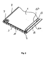
- Fig. 2 shows one of the wall elements 1, in the frame according to Fig. 1 are installed.
- the wall element 1 has receptacles 7 for locking tongues, not shown.
- an insertion bevel 8 is arranged, which complements with the other wall elements 1, 2 to a circumferential ramp.
- the wall element 1 has a retaining web 11 which prevents polyurethane from being able to escape from the frame in the assembled state.
- the wall element 1 has a protruding from the wall 5 bar 12 which shows a U-profile.
- the bar 12 is hollow and concave, inwardly offset stabilizing webs 13. These stabilizing bars 13 prevent the bar 12 from being compressed.
- the wall element 1 is designed as an injection molded part.
- seals may be attached on the flat surfaces 12a and 12b of the bar 12 seals.
- the seals can be sprayed on.
- the surface 12b faces the surface 12a.
- Fig. 3 shows one of the wall elements 2, in accordance with Fig. 1 are installed.
- the wall element 2 has latching tongues 6, which can engage in receptacles 7 of a wall element 1.
- One of the locking tongues 6 has a round passage in which a round elevation 7 of the wall element 1 according to Fig. 2 can intervene.
- Another latching tongue 6 is designed as a latching hook, which can engage behind a web, not shown, in the wall element 1.
- the wall element 2 has an insertion bevel 8, which complements the insertion bevels 8 of the wall elements 1 and 2 to form a circumferential ramp.
- the wall element 2 shows reinforcing ribs 9.
- the wall element 1 according to Fig. 2 are also associated with reinforcing ribs 9, but which are not visible because Fig. 2 the flat wall of the wall element 1 shows.
- the wall element 2 has mounting handles 10, which are designed quarter-circle. In the locked state of the quarter-circular mounting handle 10 forms a rounded corner portion of the frame.
- the Wall element 2 has a protruding from the wall 5 bar 12, which can form a head frame.
- the wall element 2 is designed as an injection molded part.
- Fig. 4 shows in an explanatory view the individual manufacturing steps for producing a cassette filter comprising a filter element 14.
- the method comprises the following production steps:
- Providing a wall element 1 and filling its inner wall with polyurethane Placing the filter element 14 on the wall element 1. placing a further wall element 1 on the filter element 14, wherein the further wall element 1 is also filled with polyurethane. The arranged on the filter element 14 wall elements 1 are locked with a wall element 2, which is also filled with polyurethane. Finally, another wall element 2 is locked to the wall elements 1. Also, the last wall element 2 is filled with polyurethane.
- the method described here allows the manufacture of a cassette filter having a frame described herein and a filter element 14 held by the frame.
Landscapes
- Chemical & Material Sciences (AREA)
- Chemical Kinetics & Catalysis (AREA)
- Filtering Of Dispersed Particles In Gases (AREA)
Applications Claiming Priority (1)
| Application Number | Priority Date | Filing Date | Title |
|---|---|---|---|
| DE102007006103A DE102007006103B4 (de) | 2007-02-02 | 2007-02-02 | Rahmen und Kassettenfilter |
Publications (2)
| Publication Number | Publication Date |
|---|---|
| EP1952870A2 true EP1952870A2 (fr) | 2008-08-06 |
| EP1952870A3 EP1952870A3 (fr) | 2012-06-20 |
Family
ID=39414377
Family Applications (1)
| Application Number | Title | Priority Date | Filing Date |
|---|---|---|---|
| EP07019822A Withdrawn EP1952870A3 (fr) | 2007-02-02 | 2007-10-10 | Cadre et filtre de cassette |
Country Status (3)
| Country | Link |
|---|---|
| US (1) | US20080184685A1 (fr) |
| EP (1) | EP1952870A3 (fr) |
| DE (1) | DE102007006103B4 (fr) |
Families Citing this family (13)
| Publication number | Priority date | Publication date | Assignee | Title |
|---|---|---|---|---|
| US7722694B2 (en) * | 2006-05-15 | 2010-05-25 | Oreck Holdings, Llc | Filter system for an air cleaner |
| US8182571B2 (en) * | 2007-12-11 | 2012-05-22 | Lennox Industries Inc. | Frame for receiving a filter element and method for providing |
| JP2015192947A (ja) * | 2014-03-31 | 2015-11-05 | キヤノン株式会社 | 集塵フィルタ |
| US10632411B2 (en) * | 2015-03-25 | 2020-04-28 | K&N Engineering, Inc. | HVAC home air filter |
| JP6659093B2 (ja) * | 2015-06-24 | 2020-03-04 | キヤノン株式会社 | フィルタフレーム、フィルタ組立体及び画像形成装置 |
| AR113747A1 (es) * | 2017-10-06 | 2020-06-10 | Candu Energy Inc | Método y aparato para filtrar fluidos en la generación de energía nuclear |
| CN112154023B (zh) | 2018-05-31 | 2022-04-26 | 康明斯过滤Ip公司 | 包括可移除式出口导管的过滤器组件 |
| US12128340B2 (en) * | 2018-11-29 | 2024-10-29 | Cummins Filtration Ip, Inc | Layered filter frame |
| USD1077171S1 (en) * | 2020-07-30 | 2025-05-27 | Airotrust LLC | Multi-piece air filter housing |
| WO2022159240A1 (fr) | 2021-01-22 | 2022-07-28 | Airotrust LLC | Enveloppe de filtre à air de cvc en plusieurs pièces, ensemble filtre et procédés associés |
| CN116367907B (zh) * | 2021-03-01 | 2026-05-26 | 王洁芳 | 可重用的过滤器系统和框架、其组装和运输方法及其用途 |
| EP4609934A1 (fr) | 2024-02-28 | 2025-09-03 | Carl Freudenberg KG | Ensemble filtre avec filtre à air et cadre de tête |
| WO2026120410A1 (fr) * | 2024-12-02 | 2026-06-11 | 3M Innovative Properties Company | Cadres réutilisables coniques vers l'extérieur pour filtres à air |
Family Cites Families (22)
| Publication number | Priority date | Publication date | Assignee | Title |
|---|---|---|---|---|
| US2405716A (en) * | 1944-03-30 | 1946-08-13 | Air Maze Corp | Filter panel |
| US2405293A (en) * | 1944-04-07 | 1946-08-06 | American Air Filter Co | Open-faced air filter frame |
| NL76433C (fr) * | 1950-03-29 | |||
| US2723731A (en) * | 1951-10-25 | 1955-11-15 | Air Maze Corp | Filter panel corner construction |
| US2869694A (en) * | 1954-07-23 | 1959-01-20 | Air Filter Corp | Frame construction for filter units |
| US2909237A (en) * | 1957-12-23 | 1959-10-20 | American Air Filter Co | Filter apparatus |
| US3494113A (en) * | 1968-05-22 | 1970-02-10 | Microtron Corp | Air filter assembly and sub-assemblies |
| BE757121A (fr) * | 1969-10-06 | 1971-03-16 | Fram Filters Ltd | Elements filtrants |
| US4885015A (en) * | 1988-10-03 | 1989-12-05 | Cambridge Filter Corporation | HEPA air filter for high temperature environments and method of fabrication |
| JPH06126119A (ja) * | 1992-10-15 | 1994-05-10 | Nippon Muki Co Ltd | エアフィルタ及びエアフィルタの組立て方法 |
| US5273563A (en) * | 1992-12-24 | 1993-12-28 | Research Products Corp. | Filter media retaining assembly for an air filter |
| DE4324388C1 (de) * | 1993-07-21 | 1994-09-01 | Alfred Buscher | Filterzelle und Verfahren zu ihrer Herstellung |
| DE19711280A1 (de) * | 1997-03-18 | 1998-09-24 | Freudenberg Carl Fa | Kassettenfilter mit Rahmen |
| US6502909B1 (en) * | 2000-10-25 | 2003-01-07 | Carrier Corporation | Media filter cabinet for gas furnace |
| US6464745B2 (en) * | 2001-01-26 | 2002-10-15 | Freudenberg Nonwovens Limited Partnership | Minipleat synthetic air filter assembly |
| DE10137926B4 (de) * | 2001-08-07 | 2004-02-05 | Carl Freudenberg Kg | Kassettenfilter |
| US6833017B2 (en) * | 2001-08-10 | 2004-12-21 | Spx Corporation | Filter assembly and method with polyimide |
| US6723150B2 (en) * | 2002-02-28 | 2004-04-20 | American Standard International Inc. | Air filter with expandable filter media |
| DE10249110B4 (de) * | 2002-10-21 | 2006-03-09 | Behr Gmbh & Co. Kg | Filtereinrichtung, Filterelement und Filterrahmen |
| DE102005031512A1 (de) * | 2005-07-06 | 2007-01-11 | Daimlerchrysler Ag | Luftfilter für eine Belüftungseinrichtung eines Kraftfahrzeugs |
| US7850390B2 (en) * | 2006-03-03 | 2010-12-14 | Lennox Industries Inc. | Frame with self-locking joint |
| US7537630B2 (en) * | 2006-08-09 | 2009-05-26 | Rps Products, Inc. | Folding filter frame and filter |
-
2007
- 2007-02-02 DE DE102007006103A patent/DE102007006103B4/de active Active
- 2007-10-10 EP EP07019822A patent/EP1952870A3/fr not_active Withdrawn
-
2008
- 2008-02-01 US US12/024,747 patent/US20080184685A1/en not_active Abandoned
Also Published As
| Publication number | Publication date |
|---|---|
| DE102007006103B4 (de) | 2012-06-06 |
| DE102007006103A1 (de) | 2008-08-14 |
| US20080184685A1 (en) | 2008-08-07 |
| EP1952870A3 (fr) | 2012-06-20 |
Similar Documents
| Publication | Publication Date | Title |
|---|---|---|
| DE102007006103B4 (de) | Rahmen und Kassettenfilter | |
| DE4327834C2 (de) | Luftfilter für den Innenraum von Kraftfahrzeugen | |
| DE102015121192A1 (de) | Rahmenprofil für ein Rahmengestell eines Schaltschranks und ein entsprechendes Rahmengestell | |
| DE102015011339B4 (de) | Filterelement mit einer umlaufenden Dichtung und Verfahren zu seiner Herstellung | |
| DE102014101404A1 (de) | Rahmenprofil eines Rahmengestells für einen Schalt- oder Verteilerschrank | |
| EP2094370B2 (fr) | Module filtrant à élément filtrant compressible, et procédé correspondants | |
| DE102016117393A1 (de) | Schaltschrank mit einem Rahmengestell und einer Innenausbaukomponente und eine entsprechende Schaltschrankanordnung sowie eine entsprechende Innenausbaukomponente | |
| DE102016103985A1 (de) | Längenvariable Schutzabdeckung mit Faltenelement | |
| DE102008021225A1 (de) | Filtermodul für Sprühkabinen | |
| DE102006009257B3 (de) | Filter für einen Staubsauger | |
| DE102009035979B4 (de) | Filtersystem | |
| DE202009006756U1 (de) | Gittertisch zur Warenpräsentation | |
| DE102014102465A1 (de) | Schaltschrank | |
| DE19714235C2 (de) | Rückenlehne für einen Kraftfahrzeugsitz | |
| DE202014006595U1 (de) | Filterelement zur Abtrennung von Partikeln aus einem partikelbelasteten Rohgasstrom | |
| EP2945828A1 (fr) | Dispositif de montage pour un élément d'habillage de paroi latérale d'un véhicule ferroviaire | |
| DE29509653U1 (de) | Schutzgitter | |
| DE102010053200A1 (de) | Zugeschnittenes Filterelement mit fünfeckigem Faltenbalg | |
| DE102009031325B4 (de) | Filterwand für raumlufttechnische Anlagen in Gebäuden | |
| DE202010007559U1 (de) | Vorrichtung zur Halterung einer eine Haltestange aufweisenden Komponente | |
| DE102010047894A1 (de) | Filterelement und Verfahren zu dessen Herstellung | |
| DE60132530T2 (de) | Filtervorrichtung für ein Gerät zur Belüftung und/oder zur Beheizung und/oder zur Klimatisierung, insbesondere für ein Kraftfahrzeug und Verwendung solch einer Filtervorrichtung | |
| DE3523690A1 (de) | Hakenkern zum zusammenbau von profilteilen | |
| DE102015009367A1 (de) | Befestiger zum lösbaren Verbinden eines Paneels an einer Struktur, Abdeckpaneel für ein Airbag und Fahrzeug mit einer Struktur und einem Airbag | |
| EP1867378A1 (fr) | Elément de filtre êtant comprimable |
Legal Events
| Date | Code | Title | Description |
|---|---|---|---|
| PUAI | Public reference made under article 153(3) epc to a published international application that has entered the european phase |
Free format text: ORIGINAL CODE: 0009012 |
|
| AK | Designated contracting states |
Kind code of ref document: A2 Designated state(s): AT BE BG CH CY CZ DE DK EE ES FI FR GB GR HU IE IS IT LI LT LU LV MC MT NL PL PT RO SE SI SK TR |
|
| AX | Request for extension of the european patent |
Extension state: AL BA HR MK RS |
|
| PUAL | Search report despatched |
Free format text: ORIGINAL CODE: 0009013 |
|
| AK | Designated contracting states |
Kind code of ref document: A3 Designated state(s): AT BE BG CH CY CZ DE DK EE ES FI FR GB GR HU IE IS IT LI LT LU LV MC MT NL PL PT RO SE SI SK TR |
|
| AX | Request for extension of the european patent |
Extension state: AL BA HR MK RS |
|
| RIC1 | Information provided on ipc code assigned before grant |
Ipc: B01D 46/00 20060101ALI20120516BHEP Ipc: B01D 35/30 20060101AFI20120516BHEP |
|
| AKY | No designation fees paid | ||
| REG | Reference to a national code |
Ref country code: DE Ref legal event code: R108 |
|
| REG | Reference to a national code |
Ref country code: DE Ref legal event code: R108 Effective date: 20130227 |
|
| STAA | Information on the status of an ep patent application or granted ep patent |
Free format text: STATUS: THE APPLICATION IS DEEMED TO BE WITHDRAWN |
|
| 18D | Application deemed to be withdrawn |
Effective date: 20121221 |