EP1952888B1 - Ensemble d'outil multifonctions pour un outil de traitement d'une machine de traitement de matériaux - Google Patents
Ensemble d'outil multifonctions pour un outil de traitement d'une machine de traitement de matériaux Download PDFInfo
- Publication number
- EP1952888B1 EP1952888B1 EP07023567A EP07023567A EP1952888B1 EP 1952888 B1 EP1952888 B1 EP 1952888B1 EP 07023567 A EP07023567 A EP 07023567A EP 07023567 A EP07023567 A EP 07023567A EP 1952888 B1 EP1952888 B1 EP 1952888B1
- Authority
- EP
- European Patent Office
- Prior art keywords
- tool
- reducer
- set forth
- arcuate
- cavity
- Prior art date
- Legal status (The legal status is an assumption and is not a legal conclusion. Google has not performed a legal analysis and makes no representation as to the accuracy of the status listed.)
- Active
Links
Images


Classifications
-
- B—PERFORMING OPERATIONS; TRANSPORTING
- B02—CRUSHING, PULVERISING, OR DISINTEGRATING; PREPARATORY TREATMENT OF GRAIN FOR MILLING
- B02C—CRUSHING, PULVERISING, OR DISINTEGRATING IN GENERAL; MILLING GRAIN
- B02C18/00—Disintegrating by knives or other cutting or tearing members which chop material into fragments
- B02C18/06—Disintegrating by knives or other cutting or tearing members which chop material into fragments with rotating knives
- B02C18/16—Details
- B02C18/18—Knives; Mountings thereof
- B02C18/182—Disc-shaped knives
- B02C18/184—Disc-shaped knives with peripherally arranged demountable cutting tips or elements
-
- B—PERFORMING OPERATIONS; TRANSPORTING
- B02—CRUSHING, PULVERISING, OR DISINTEGRATING; PREPARATORY TREATMENT OF GRAIN FOR MILLING
- B02C—CRUSHING, PULVERISING, OR DISINTEGRATING IN GENERAL; MILLING GRAIN
- B02C13/00—Disintegrating by mills having rotary beater elements ; Hammer mills
- B02C13/02—Disintegrating by mills having rotary beater elements ; Hammer mills with horizontal rotor shaft
- B02C13/06—Disintegrating by mills having rotary beater elements ; Hammer mills with horizontal rotor shaft with beaters rigidly connected to the rotor
-
- B—PERFORMING OPERATIONS; TRANSPORTING
- B02—CRUSHING, PULVERISING, OR DISINTEGRATING; PREPARATORY TREATMENT OF GRAIN FOR MILLING
- B02C—CRUSHING, PULVERISING, OR DISINTEGRATING IN GENERAL; MILLING GRAIN
- B02C13/00—Disintegrating by mills having rotary beater elements ; Hammer mills
- B02C13/26—Details
- B02C13/28—Shape or construction of beater elements
-
- B—PERFORMING OPERATIONS; TRANSPORTING
- B02—CRUSHING, PULVERISING, OR DISINTEGRATING; PREPARATORY TREATMENT OF GRAIN FOR MILLING
- B02C—CRUSHING, PULVERISING, OR DISINTEGRATING IN GENERAL; MILLING GRAIN
- B02C13/00—Disintegrating by mills having rotary beater elements ; Hammer mills
- B02C13/26—Details
- B02C13/28—Shape or construction of beater elements
- B02C13/2804—Shape or construction of beater elements the beater elements being rigidly connected to the rotor
-
- B—PERFORMING OPERATIONS; TRANSPORTING
- B02—CRUSHING, PULVERISING, OR DISINTEGRATING; PREPARATORY TREATMENT OF GRAIN FOR MILLING
- B02C—CRUSHING, PULVERISING, OR DISINTEGRATING IN GENERAL; MILLING GRAIN
- B02C13/00—Disintegrating by mills having rotary beater elements ; Hammer mills
- B02C13/26—Details
- B02C13/288—Ventilating, or influencing air circulation
-
- B—PERFORMING OPERATIONS; TRANSPORTING
- B02—CRUSHING, PULVERISING, OR DISINTEGRATING; PREPARATORY TREATMENT OF GRAIN FOR MILLING
- B02C—CRUSHING, PULVERISING, OR DISINTEGRATING IN GENERAL; MILLING GRAIN
- B02C18/00—Disintegrating by knives or other cutting or tearing members which chop material into fragments
- B02C18/06—Disintegrating by knives or other cutting or tearing members which chop material into fragments with rotating knives
- B02C18/14—Disintegrating by knives or other cutting or tearing members which chop material into fragments with rotating knives within horizontal containers
- B02C18/145—Disintegrating by knives or other cutting or tearing members which chop material into fragments with rotating knives within horizontal containers with knives spaced axially and circumferentially on the periphery of a cylindrical rotor unit
Definitions
- the present invention relates generally to material processing machine as defined in claim 21 and, more particularly, to a multi-functional tool assembly and a processing tool of a material processing machine as defined in the preamble of claims 1 and 11 and known from US-A-4725098 .
- the waste processing machine typically includes a rotor assembly for reducing the waste material as the rotor assembly rotates.
- a rotor assembly for a waste processing machine is disclosed in U.S. Patent No. 5,863,003, issued January 26, 1999, to Smith , entitled “WASTE PROCESSING MACHINE".
- the rotor assembly includes a rotor having a plurality of spaced pairs of mounting arms.
- the rotor assembly also includes a processing tool mounted to each pair of mounting arms.
- An example of a processing tool is disclosed in U.S. Patent No.
- the processing tool includes a tool holder attached to the mounting arms of the rotor assembly by fasteners.
- the tool holder has a pair of spaced arms extending radially with a tool for reducing waste product attached to one arm and a wear bar or raker for depth limiting guiding attached to the other arm.
- the tool has a head, a shaft, and a waste reducer attached to the head by suitable means such as brazing.
- the shaft of the tool is extended through an aperture in the arm of the processing tool and secured thereto by a fastener such as a nut.
- the force on the waste reducer may cause the brazing to give way and the waste reducer may become detached from the head. This is due to shear forces acting on the waste reducer.
- the shear forces produce a sideways force vector acting on either side of the waste reducer. This causes the brazing, which is in compression, to be tensioned and give way, which is undesired.
- US 4 725 098 A discloses a cutting bit with hard facing wherein a shaft/shank portion is provided having an integral conical head, said conical head carrying a hard pointed insert made of tongues than carbide.
- US 6 845 931 A discloses a multi-functional tool assembly having a cutter waste reducer made of carbide and a tool with a shaft as well as a fan. This fan is attached to a head being integral with a shaft.
- the present invention is a multi-functional tool assembly for a material processing machine comprising the features of claim 1. Moreover the invention is concerned with a processing tool and a material processing machine as defined in claims 11 and 21, respectively.
- a multi-functional tool assembly is provided for a processing tool of a material processing machine.
- the multi-functional tool assembly is a single multi-functional tool that allows material to be reduced and aggressively outputs the reduced material from the rotor assembly in the material processing machine.
- the multi-functional tool assembly is that the multi-functional tool has a cavity with an arcuate surface for the material reducer to reduce or prevent the material reducer from disengaging the tool.
- the multi-functional tool assembly has a cavity with an arcuate surface and the material reducer has a complementary arcuate surface to reduce or redirect the shear force vector acting on the tool.
- FIG. 1 is a perspective view of a material processing machine.
- FIG. 2 is a fragmentary elevational view of a rotor assembly of the material processing machine of FIG. 1 .
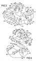
- FIG. 3 is an enlarged fragmentary elevational view of a processing tool, according to the present invention, of the rotor assembly in circle 3 of FIG. 2 .
- FIG. 4 is an exploded perspective view of the processing tool of FIG. 3 .
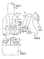
- FIG. 5 is an elevational front view of a multi-functional tool assembly, according to the present invention, of the processing tool of FIG. 4 .
- FIG. 6 is an elevational side view of the multi-functional tool assembly of FIG. 5 .
- FIG. 7 is a plan view of the multi-functional tool assembly of FIG. 5 .
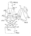
- FIG. 8 is an elevational front view of another embodiment, according to the present invention, of a multi-functional tool assembly of the processing tool of FIG. 4 .
- FIG. 9 is an elevational side view of the multi-functional tool assembly of FIG. 8 .
- FIG. 10 is a plan view of the multi-functional tool assembly of FIG. 8 .
- the material processing machine 10 includes an infeed system 12, a material reducing system 14, and a discharge system 16.
- Material enters the material processing machine 10 through the infeed system 12 where it is directed to the material reducing system 14.
- the material reducing system 14 reduces the material and directs it to the discharge system 16 where the reduced material is expelled from the material processing machine 10.
- the material processing machine 10 may be supported on a trailer framework 18 having a tongue mount 20 provided at a front thereof and wheels 22 near a rear of the framework 18. It should be appreciated that, with this structure, the infeed system 12 and material reducing system 14 can be transported together while the discharge system 16 can be transported separately therefrom. It should also be appreciated that the material may take many forms and varieties such as waste, boards, roots, etc. and processed into different types such as waste, sawdust, wood chips, etc.
- the infeed system 12 includes an infeed conveyor 24 and a feed wheel assembly 26.
- the infeed conveyor 24 has a terminal end 27 spaced a predetermined distance such as 6,35 mm (one quarter inches (0.25 inches)) from a rotor assembly 30 to be described of the material reducing system 14.
- the infeed conveyor 24 is the sole means of support for the material and acts as a primary anvil for reducing the material by the rotor assembly 30 to be described.
- Opposed side walls 28 are provided on opposite sides of the infeed conveyor 24 to contain the material. It should be appreciated that material is placed on the infeed conveyor 24, which moves the material into contact with the feed wheel assembly 26, which, in turn, rotates and feeds the material into contact with the rotor assembly 30 of the material reducing system 14.
- the material reducing system 14 includes a rotor assembly, according to the present invention and generally indicated at 30.
- the material reducing system 14 also includes a housing 32 disposed about the rotor assembly 30 and a plurality of regrind augers 34 positioned at a bottom of the housing 32.
- the material reducing system 14 further includes a movable concave screen 36 and a fixed concave screen 38 at a rear of the housing 32. It should be appreciated that the material reducing system 14 reduces material by the rotor assembly 30, which passes through the screens 36,38 to the discharge system 16. It should also be appreciated that the regrind augers 34 move reduced material or product into contact with the rotor assembly 30 for further reduction to pass through the screens 36,38.
- the rotor assembly 30 also includes a rotatable rotor 40 disposed within the housing 32 above the regrind augers 34.
- the rotor 40 is a generally cylindrical tube having a longitudinal axis.
- the rotor 40 is mounted to a coaxially disposed shaft 42 by multiple braces 44 extending tangentially from an outer surface of the shaft 42 to an inner surface 45 of the rotor 40.
- each brace 44 is an elongated plate-like member fixed tangentially to the shaft 42 by suitable means such as welding and is similarly secured to the inner surface 45 of the rotor 40 by suitable means such as welding.
- a power source (not shown) is connected to the shaft 42 in a well-known manner and is adapted to turn the shaft 42 and rotor 40.
- the rotor assembly 30 also includes a plurality of spaced pairs of mounting arms 46 mounted to an outer surface 47 of the rotor 40 by suitable means such as welding.
- Each mounting arm 46 is generally trapezoidal in shape and includes at least one, preferably a pair of spaced apertures 49 extending therethrough.
- the mounting arms 46 are wrapped about the rotor 40 in a first spiral and a second spiral spaced or offset from the first spiral.
- the rotor assembly 30 further includes a plurality of processing tools, according to the present invention and generally indicated at 50, mounted to the mounting arms 46.
- the first spiral and the second spiral of mounting arms 46 extend about the rotor 40 so that in one rotation of the rotor assembly 30, every point on an imaginary axial line segment positioned adjacent to the rotor assembly 30 will be contacted by the processing tools 50 mounted to the rotor assembly 30.
- Each of the processing tools 50 includes a tool holder 52 having a general "C" shape.
- the tool holder 52 has a body 54 extending circumferentially and a first or trailing arm 56 extending radially at an angle therefrom with a first aperture 58 extending therethrough.
- the tool holder 52 also includes a second or leading arm 60 extending radially at an angle from the body 54.
- the tool holder 52 includes an aperture 64 and 66 at a lower radial end of the first arm 56 and second arm 60, respectively, and extending axially therethrough.
- the body 54 has a width or thickness less than the first arm 56 and the second arm 60.
- the tool holder 52 is continuous, integral, unitary, and made as one-piece. It should be appreciated that the apertures 64,66 of the tool holder 52 are aligned with the apertures 49 of the mounting arms 46.
- the rotor assembly 30 includes at least one, preferably a pair of fasteners such as bolts 68 and nuts 70 for retaining the processing tools 50 to the mounting arms 46.
- the bolts 68 extend through the apertures 49 in the mounting arms 46 and the apertures 64,66 of the tool holder 52 and threadably engage the nuts 70. It should be appreciated that the tool holder 52 is disposed between the mounting arms 46.
- the processing tool 50 also includes a multi-functional tool assembly, generally indicated at 74 and according to the present invention, attached to the tool holder 52.
- the multi-functional tool assembly 74 includes a multi-functional tool 76 to aggressively intake the material, reduce the material, and aggressively output the reduced material by pushing the reduced material to the screens 36,38 and out of the rotor assembly 30.
- the multi-functional tool 76 includes a head 78, fan 80, and shaft 82.
- the head 78, fan 80, and shaft 82 are made of a metal material and are made as a single forging.
- the head 78, fan 80, and shaft 82 are a monolithic structure being integral, unitary, and one-piece.
- the multi-functional tool 76 also includes a cavity or pocket, generally indicated at 83, between the head 78 and the fan 80 to receive a material reducer 84 to be described.
- the cavity 83 includes a base wall 83a, which is generally planar, and extends laterally and longitudinally.
- the cavity 83 also includes a side wall 83b, which is generally arcuate in shape such as concave, and extending vertically or generally perpendicular to the base wall 83a. It should be appreciated that the cavity 83 is formed by a mill (not shown) that plunges into the forging in a secondary machining operation to machine the cavity 83 therein.
- the multi-functional tool assembly 74 also includes a material reducer, generally indicated at 84, disposed in the cavity 83.
- the material reducer 84 is a splitter to split or reduce the material.
- the material reducer 84 has a rear surface 84a that is generally arcuate in shape such as convex and extending laterally.
- the material reducer 84 also has a pair of opposed side surfaces 84b extending longitudinally from the rear surface 84a.
- the material reducer 84 further has a pair of front surfaces 84c extending longitudinally and inwardly toward each other at an angle such as thirty-two degrees (32°) to a planar tip surface 84d.
- the planar tip surface 84d extends axially or vertically and inwardly at an angle such as two degrees (2°).
- the material reducer 84 also has a generally planar bottom surface 84e and an arcuate or convex top surface 84f.
- the material reducer 84 is disposed in the cavity 83 such that the rear surface 84a contacts the side wall 83b and the bottom surface 84e contacts the base wall 83a.
- the material reducer 84 has a lateral width less than a lateral width of the side wall 83b of the cavity 83.
- the material reducer 84 is attached to the head 78 by suitable means such as brazing.
- the material reducer 84 is made of a carbide material. It should be appreciated that, in other embodiments, the material reducer 84 is a cutter to cut and reduce the material.
- the fan 80 is disposed radially below the material reducer 84.
- the fan 80 is generally rectangular in shape.
- the fan 80 has a width greater than the height thereof.
- the fan 80 is disposed radially one half inch back or inward from an outer periphery of the material reducer 84 to provide 25,4 mm (one inch) of clearance between the fan 80 and an inner surface of the housing 32 of the rotor assembly 30.
- the shaft 82 is disposed opposite the fan 80 and extends outwardly therefrom.
- the shaft 82 extends axially through the aperture in the first arm 56 and is removably secured to the first arm 56 by a suitable mechanism such as a nut 86 threadably engaging the shaft 82.
- the fan 80 is not a cutting tooth and does not reduce the material, but aggressively outputs the reduced material.
- the material reducers 84 are typically one inch apart axially and the fans 80 are typically two inches wide axially to cover a space between the material reducers 84.
- the fan 80 may have any suitable shape or area to push reduced material for aggressive output thereof. It should still further be appreciated that the aggressive output of the fan 80 assists in reducing wear to other components of the rotor assembly 30.
- the multi-functional tool 76 includes a tab 87 extending from the head 78 and behind the fan 80.
- the tab 87 is generally rectangular in shape.
- the tab 87 has a width less than a width of the head 78.
- the tool holder 52 may include a slot (not shown) in the first arm 56 to receive the tab 87 to orientate the multi-functional tool 76 and prevent rotation of the multi-functional tool 76 by locking it in place.
- the tool holder 52 may include a pair of spaced tabs (not shown) extending outwardly from the first arm 56 to receive the tab 87 therebetween to orientate the multi-functional tool 76 and prevent rotation of the multi-functional tool 76 by locking it in place.
- the head 78, fan 80, shaft 82, and tab 87 are made of a metal material and are made as a single forging. It should be appreciated that the head 78, fan 80, shaft 82, and tab 87 are a monolithic structure being integral, unitary, and one-piece.
- the processing tool 50 also a raker assembly, generally indicated at 88, attached to the second arm 60.
- the raker assembly 88 may be fixed or removable from the second arm 60.
- the raker assembly 88 is removable and replaceable.
- the raker assembly 88 includes a raker 90 disposed in a recess 92 on a forward side of a free end of the second arm 60.
- the recess 92 is generally rectangular in shape and has a lower surface 94 and a side surface 96.
- the raker 90 includes a raker wear bar 98 disposed in the recess 92.
- the raker wear bar 98 is generally rectangular in shape.
- the raker wear bar 98 is of such a length to extend outwardly beyond a radial end surface 100 of the second arm 60 when disposed in the recess 92.
- the raker wear bar 98 rests against and is supported by the lower surface 94 and side surface 96.
- the raker wear bar 98 has an aperture 102 extending axially therein for a function to be described.
- the raker wear bar 98 is made of a metal material such as a one-piece hard faced material such as Trimay.
- the raker assembly 88 also includes another recess 108 on a rear side of a free end of the second arm 60 opposite the recess 92.
- the recess 108 is generally rectangular in shape.
- the raker assembly 88 includes an aperture 110 extending from the recess 108 to the recess 92 in the second arm 60.
- the raker assembly 88 further includes a fastener such as a bolt 112 to removably secure the raker wear bar 98 to the second arm 60.
- the bolt 112 has a head 114 disposed in the recess 108 and a threaded shaft 116 extending axially from the head 114 and through the aperture 110 in the second arm 60 and threadably engaging the threads of the aperture 102 in the raker wear bar 98.
- the bolt 112 is of a sufficient length to extend through the second arm 60 and into the raker wear bar 98 in an unobstructed manner without penetrating the front face of the raker wear bar 98. It should be appreciated that the second arm 60 operates as a depth-limiting guide.
- the processing tool 50 may include at least one notch 118 in the tool holder 52 to control breakage of the processing tool 50.
- the processing tool 50 includes a first notch 118 in the body 54 adjacent to the first arm 56 between the first arm 56 and second arm 60 on a radial outer side thereof and a second notch 118 in the body 54 adjacent to the second arm 60 between the first arm 56 and second arm 60 on a radial inner side thereof.
- the notches 118 extend axially across the body 54 of the tool holder 52.
- the notches 118 are generally arcuate in shape and have a depth of approximately, 6,35 mm (one-quarter inches (0.25 inches)). The position, shape, and depth of the notches 118 are varied to control breakage of the tool holder 52 relative to either the first arm 56 or second arm 60 of the tool holder 52.
- the rotor 40 rotates the processing tools 50.
- the multi-functional tool assembly 74 contacts material or product, such as wood, first approximately three revolutions before the raker wear bar 98 contacts the material or product.
- the material reducer 84 splits the material to reduce the material and the fan 80 pushes the reduced material toward the screens 36,38 of the rotor assembly 30. If the material is stuck or lodged by the multi-functional tool assembly 74 in the material processing machine 10, the first arm 56 will concentrate stress on the tool holder 52 in the notch 118 adjacent to the first arm 56 and cause a breakage by propagating a crack from the notch 118 radially across the body 54 of the tool holder 52.
- the first arm 56 will then pivot about the bolt 68, which acts as a first pivot pin and remains attached to the mounting arms 46 to prevent damage to the rotor assembly 30.
- the remainder of the tool holder 52 including the body 54 and second arm 60 will pivot about the other bolt 68, which acts as a second pivot pin and remains attached to the mounting arms 46 to prevent damage to the rotor assembly 30.
- the tool holder 52 can then be replaced. It should be appreciated that the multi-functional tool assembly 74 aggressively intakes the material, reduces the material, and aggressively outputs the reduced material from the rotor assembly 30.
- the material reducer 84 may be removed by unsoldering or unbrazing the material reducer 84 from the head 78 of the multi-functional tool 76.
- the worn material reducer 84 can be discarded and replaced with a new material reducer 84.
- the material reducer 84 is disposed in the cavity 83 and soldered or brazed to the head 78 of the multi-functional tool 76 to secure the material reducer 84 in place.
- the bolt 112 may be removed by unthreading the threaded shaft 116 from the raker wear bar 98.
- the worn raker wear bar 98 can be discarded and replaced with a new raker wear bar 98.
- the bolt 112 is then threaded with the threads of the aperture 102 to secure the raker wear bar 98 in place.
- FIGS. 8 through 10 another embodiment, according to the present invention, of the multi-functional tool assembly 74 is shown.
- Like parts of the multi-functional tool assembly 174 have like reference numerals increased by one hundred (100).
- the multi-functional tool assembly 174 is attached to the tool holder 52.
- the multi-functional tool assembly 174 includes a multi-functional tool 176 to aggressively intake the material, reduce the material, and aggressively output the reduced material by pushing the reduced material to the screens 36,38 and out of the rotor assembly 30.
- the multi-functional tool 176 includes a head 178, fan 180, and shaft 182.
- the head 178, fan 180, and shaft 182 are made of a metal material and are made as a single forging.
- the head 178, fan 180, and shaft 182 are a monolithic structure being integral, unitary, and one-piece.
- the multi-functional tool assembly 174 includes a cavity or pocket, generally indicated at 183, between the head 178 and the fan 180 to receive a material reducer 184 to be described.
- the cavity 183 includes a base wall 183a, which is generally planar, and extends laterally and longitudinally.
- the cavity 183 also includes a side wall 183b, which is generally arcuate in shape such as concave, and extending vertically or generally perpendicular to the base wall 183a. It should be appreciated that the cavity 183 is formed by a mill (not shown) that plunges into the forging in a secondary machining operation to machine the cavity 183 therein.
- the multi-functional tool assembly 174 includes a material reducer, generally indicated at 184, disposed in the cavity 183.
- the material reducer 184 is a cutter to cut or reduce the material.
- the material reducer 184 has a rear surface 184a that is arcuate in shape such as convex and extending laterally.
- the material reducer 184 also has a pair of opposed side surfaces 184b extending longitudinally from the rear surface 184a.
- the material reducer 184 also has a generally planar front surface 184c extending laterally between the side surfaces 184b.
- the material reducer 184 further has a generally planar bottom surface and an arcuate or convex top surface 184f.
- the material reducer 184 is disposed in the cavity 183 such that the rear surface 184a contacts the side wall 183b and the bottom surface contacts the base wall 183a.
- the material reducer 184 has a lateral width greater than a lateral width of the side wall 183b of the cavity 183.
- the material reducer 184 is attached to the head 178 by suitable means such as brazing.
- the material reducer 184 is made of a carbide material.
- the multi-functional tool 176 includes a tab 187 extending from the head 178 and behind the fan 180.
- the tab 187 is generally rectangular in shape.
- the tab 187 has a width less than a width of the head 178.
- the tool holder 52 may include a slot (not shown) in the first arm 58 to receive the tab 187 to orientate the multi-functional tool 176 and prevent rotation of the multi-functional tool 176 by locking it in place.
- the tool holder 52 may include a pair of spaced tabs (not shown) extending outwardly from the first arm 58 to receive the tab 187 therebetween to orientate the multi-functional tool 176 and prevent rotation of the multi-functional tool 176 by locking it in place.
- the head 178, fan 180, shaft 182, and tab 187 are made of a metal material and are made as a single forging. It should be appreciated that the head 178, fan 180, shaft 182, and tab 187 are a monolithic structure being integral, unitary, and one-piece.
- the rotor 40 rotates the processing tool 50.
- the multi-functional tool assembly 174 contacts material or product, such as wood, first approximately three revolutions before the raker wear bar 98 contacts the material or product.
- the waste reducer 184 cuts the material to reduce the material and the fan 180 pushes the reduced material toward the screens 36,38 of the rotor assembly 30. It should be appreciated that the multi-functional tool assembly 174 aggressively intakes the material, reduces the material, and aggressively outputs the reduced material from the rotor assembly 30.
- the material reducer 184 may be removed by unsoldering or unbrazing the material reducer 184 from the head 178 of the multi-functional tool 176.
- the worn material reducer 184 can be discarded and replaced with a new material reducer 184.
- the material reducer 184 is disposed in the recess and soldered or brazed to the head 178 of the multi-functional tool 176 to secure the material reducer 184 in place.
Landscapes
- Engineering & Computer Science (AREA)
- Food Science & Technology (AREA)
- Crushing And Pulverization Processes (AREA)
Claims (21)
- Ensemble outil multifonctionnel (74, 174) pour une machine de traitement de matériau comprenant :un unique outil (76, 176) incluant une tête (78, 178) et un arbre (82, 182) intégralement formés à l'intérieur, ladite tête ayant une cavité (83, 183) avec une surface arquée ; etun réducteur de matériau (84, 184) adapté pour réduire un matériau au sein de la machine de traitement de matériau, ledit réducteur de matériau étant disposé dans ladite cavité et ayant une surface arquée complémentaire à ladite surface arquée de ladite cavité.caractérisé en ce que ledit unique outil (76, 176) inclut un ventilateur (80, 180), grâce à quoi ladite tête (78, 178), ledit ventilateur (80, 180) et ledit arbre (82, 182) sont réalisés comme un unique élément de forgeage.
- Ensemble outil multifonctionnel tel qu'énoncé dans la revendication 1 où ledit ventilateur (80, 180) est disposé radialement en dessous dudit réducteur de matériau (84, 184) pour faire sortir de manière agressive un matériau réduit à partir de la machine de traitement de matériau.
- Ensemble outil multifonctionnel tel qu'énoncé dans la revendication 1 où ladite cavité arquée (83, 183) a une paroi latérale (83b, 183b) qui est généralement de forme arquée pour former ladite surface arquée et une paroi de base (83a, 183a) qui est généralement de forme planaire.
- Ensemble outil multifonctionnel tel qu'énoncé dans la revendication 3 où ledit réducteur de matériau (84, 184) est un couteau constitué d'un matériau carburé pour couper un matériau.
- Ensemble outil multifonctionnel tel qu'énoncé dans la revendication 3 où ledit réducteur de matériau (184) a une surface arrière généralement arquée (184a), des surfaces latérales opposées (184b) s'étendant à partir de ladite surface arrière, et une surface avant généralement planaire (184c) s'étendant à partir desdites surfaces latérales.
- Ensemble outil multifonctionnel tel qu'énoncé dans la revendication 3 où ledit réducteur de matériau (184) a une largeur latérale supérieure à une largeur latérale de ladite paroi latérale (183b) de ladite cavité (183).
- Ensemble outil multifonctionnel tel qu'énoncé dans la revendication 3 où ledit réducteur de matériau (83, 183) est un séparateur constitué d'un matériau carburé pour séparer un matériau.
- Ensemble outil multifonctionnel tel qu'énoncé dans la revendication 3 où ledit réducteur de matériau (84) a une surface arrière généralement arquée (84a), des surfaces latérales opposées (84b) s'étendant à partir de ladite surface arrière, et une paire de surfaces avant (84c) s'étendant à partir desdites surfaces latérales, et une surface de pointe généralement planaire (84d) s'étendant entre lesdites surfaces avant.
- Ensemble outil multifonctionnel tel qu'énoncé dans la revendication 3 où ledit réducteur de matériau (84) a une largeur latérale inférieure à une largeur latérale de ladite paroi latérale (83b) de ladite cavité (83).
- Ensemble outil multifonctionnel tel qu'énoncé dans la revendication 1 incluant un brasage pour fixer ledit réducteur de matériau (84,184) à ladite tête.
- Outil de traitement (50) pour une machine de traitement de matériau comprenant :un porte-outil (52) pour fixation à un ensemble rotor (30) de la machine de traitement de matériau ; etun unique ensemble outil multifonctionnel (74, 174) fixé audit porte-outil pour réduire un matériau comprenant un réducteur de matériau (84, 184) adapté pour réduire un matériau et un unique outil (76, 176) pour supporter ledit réducteur de matériau, ledit outil multifonctionnel incluant une tête (78, 178) et un arbre (82, 182) intégralement formés à l'intérieur, ladite tête ayant une cavité avec une surface arquée (83, 183) pour recevoir ledit réducteur de matériau et ledit réducteur de matériau ayant une surface arquée complémentaire à la surface de ladite cavité arquée,caractérisé en ce que ledit outil inclut un ventilateur (80, 180), grâce à quoi ladite tête (78, 178), ledit ventilateur (80, 180) et ledit arbre (82, 182) sont réalisés comme un unique élément de forgeage.
- Outil de traitement tel qu'énoncé dans la revendication 11 où ledit ventilateur (80, 180) est disposé radialement en dessous dudit réducteur de matériau pour faire sortir de manière agressive un matériau réduit à partir de la machine de traitement de matériau.
- Outil de traitement tel qu'énoncé dans la revendication 11 où ladite cavité arquée (83, 183) a une paroi latérale (83b, 183b) qui est généralement de forme arquée et une paroi de base (83a, 183a) qui est généralement de forme planaire.
- Outil de traitement tel qu'énoncé dans la revendication 13 où ledit réducteur de matériau (84, 184) est un couteau constitué d'un matériau carburé pour couper un matériau.
- Outil de traitement tel qu'énoncé dans la revendication 13 où ledit réducteur de matériau (184) a une surface arrière généralement arquée (184a), des surfaces latérales opposées (184b) s'étendant à partir de ladite surface arrière, et une surface avant généralement planaire (184c) s'étendant à partir desdites surfaces latérales.
- Outil de traitement tel qu'énoncé dans la revendication 13 où ledit réducteur de matériau (184) a une largeur latérale supérieure à une largeur latérale de ladite paroi latérale (183b) de ladite cavité (183).
- Outil de traitement tel qu'énoncé dans la revendication 13 où ledit réducteur de matériau (84, 184) est un séparateur constitué d'un matériau carburé pour séparer un matériau.
- Outil de traitement tel qu'énoncé dans la revendication 13 où ledit réducteur de matériau (84) a une surface arrière généralement arquée (84a), des surfaces latérales opposées (84b) s'étendant à partir de ladite surface arrière, et une paire de surfaces avant (84c) s'étendant à partir desdites surfaces latérales, et une surface de pointe généralement planaire (84d) s'étendant entre lesdites surfaces avant.
- Outil de traitement tel qu'énoncé dans la revendication 13 où ledit réducteur de matériau (84) a une largeur latérale inférieure à une largeur latérale de ladite paroi latérale (83b) de ladite cavité (83).
- Outil de traitement tel qu'énoncé dans la revendication 11 incluant un brasage pour fixer ledit réducteur de matériau à ladite tête.
- Machine de traitement de matériau (10) comprenant :un ensemble rotor (30) ;au moins un porte-outil (52) fixé audit ensemble rotor, où ledit au moins un porte-outil inclut un premier bras (56) s'étendant radialement et un second bras (60) s'étendant radialement et espacé dudit premier bras ; etun unique ensemble outil multifonctionnel (174, 74) comprenant un réducteur de matériau (84, 184) pour réduire un matériau et un unique outil (76, 176) pour supporter ledit réducteur de matériau ; ledit outil incluant une tête (78, 178), un ventilateur (80, 180), et un arbre (82, 182) intégralement formés à l'intérieur et réalisés comme un unique élément de forgeage ; ladite tête ayant une cavité arquée (83, 183) pour recevoir ledit réducteur de matériau, et ledit réducteur de matériau ayant une surface arquée complémentaire à une surface de ladite cavité arquée ; ledit ventilateur étant disposé radialement en dessous dudit réducteur de matériau pour faire sortir de manière agressive le matériau réduit à partir dudit ensemble rotor ; et ledit arbre (82, 182) étant disposé à l'opposé dudit ventilateur (80, 180) et s'étendant vers l'extérieur à partir de là et fixé à l'un ou l'autre dudit premier bras et dudit second bras dudit porte-outil.
Applications Claiming Priority (1)
| Application Number | Priority Date | Filing Date | Title |
|---|---|---|---|
| US11/702,452 US7726594B2 (en) | 2001-10-03 | 2007-02-05 | Multi-functional tool assembly for processing tool of material processing machine |
Publications (2)
| Publication Number | Publication Date |
|---|---|
| EP1952888A1 EP1952888A1 (fr) | 2008-08-06 |
| EP1952888B1 true EP1952888B1 (fr) | 2012-08-01 |
Family
ID=39467224
Family Applications (1)
| Application Number | Title | Priority Date | Filing Date |
|---|---|---|---|
| EP07023567A Active EP1952888B1 (fr) | 2007-02-05 | 2007-12-05 | Ensemble d'outil multifonctions pour un outil de traitement d'une machine de traitement de matériaux |
Country Status (3)
| Country | Link |
|---|---|
| US (1) | US7726594B2 (fr) |
| EP (1) | EP1952888B1 (fr) |
| ES (1) | ES2392547T3 (fr) |
Cited By (2)
| Publication number | Priority date | Publication date | Assignee | Title |
|---|---|---|---|---|
| US9233375B2 (en) | 2011-03-29 | 2016-01-12 | Richard S. Kennedy | Wood chipper, control system therefor, and method thereof |
| US10589290B2 (en) | 2016-04-06 | 2020-03-17 | Bandit Industries, Inc. | Waste processing machine feed assist system |
Families Citing this family (23)
| Publication number | Priority date | Publication date | Assignee | Title |
|---|---|---|---|---|
| US20110062266A1 (en) * | 2001-10-03 | 2011-03-17 | Leward Nile Smith | Multi-functional tool assembly for processing tool of material processing machine |
| US7896274B2 (en) * | 2006-01-30 | 2011-03-01 | Vermeer Manufacturing Company | Machine with snag anvil |
| US8061640B2 (en) * | 2009-02-17 | 2011-11-22 | Morbark, Inc. | Interchangable chipper inserts for wood grinder |
| WO2010129268A2 (fr) | 2009-04-28 | 2010-11-11 | Vermeer Manufacturing Company | Machine à broyer des matériaux convertible entre une configuration de broyage et configuration de hachage |
| US8245961B2 (en) | 2009-06-08 | 2012-08-21 | Vermeer Manufacturing Company | Material reducing apparatus having features for enhancing reduced material size uniformity |
| US8844853B2 (en) * | 2010-09-02 | 2014-09-30 | Vermeer Manufacturing Company | Reducing component for a comminution machine |
| US9125347B2 (en) | 2010-12-23 | 2015-09-08 | Michael D. Morey | Waste processing system, machine and method thereof |
| US9192938B2 (en) | 2011-01-11 | 2015-11-24 | Troy S. Grover | Knife assembly for a waste processing machine and method of assembly thereof |
| US9981405B2 (en) | 2011-03-29 | 2018-05-29 | Bandit Industries, Inc. | Wood chipper, control system therefor, and method thereof |
| US9227192B2 (en) | 2011-06-06 | 2016-01-05 | David Roy | Chipper striker assembly |
| US9095854B2 (en) | 2011-06-06 | 2015-08-04 | David Roy | Chipper striker assembly |
| DE102011085520B4 (de) * | 2011-10-31 | 2017-05-04 | General Electric Technology Gmbh | Hammer einer Schlägermühle |
| US9370776B2 (en) | 2013-04-29 | 2016-06-21 | Vermeer Manufacturing Company | Mounting block for attaching a reducing element to a rotary drum |
| US10589288B2 (en) * | 2015-04-26 | 2020-03-17 | Justin H Beard | Cradle system for fragmentation machines |
| CA2943196C (fr) | 2015-09-27 | 2018-04-03 | Bandit Industries, Inc. | Systeme de reduction de materiau et outils de traitement destines a une machine de traitement de materiau |
| US10792663B2 (en) * | 2015-10-05 | 2020-10-06 | West Salem Machinery Company | Multi-blade hammer assembly |
| DE102015119119A1 (de) * | 2015-11-06 | 2017-05-11 | Betek Gmbh & Co. Kg | Werkzeugsystem |
| WO2017161246A1 (fr) | 2016-03-17 | 2017-09-21 | Bandit Industries Inc. | Dispositif de sécurité pour machine de traitement de déchets |
| US10357776B2 (en) * | 2016-09-09 | 2019-07-23 | Comcorp, Inc. | Impact cutter blade and holder system and method |
| CA2994663C (fr) | 2017-02-10 | 2021-03-09 | Smoracy, Llc | Machine de traitement de materiau avec un systeme de colorieur et procedes de reduction et de colorisation des dechets |
| CA3055050C (fr) | 2018-09-10 | 2026-02-17 | Bandit Industries, Inc. | Machine d`usinage de materiau dotee d`un systeme de colorisation et methodes de reduction des dechets de colorisation |
| EP4496660A4 (fr) | 2022-04-22 | 2025-07-02 | Bandit Ind Inc | Machine de traitement |
| USD1065265S1 (en) | 2023-04-24 | 2025-03-04 | Bandit Industries, Inc. | Tool body |
Family Cites Families (103)
| Publication number | Priority date | Publication date | Assignee | Title |
|---|---|---|---|---|
| US589236A (en) | 1897-08-31 | Crusher and pulverizer | ||
| US190675A (en) | 1877-05-15 | Improvement in hominy-mills | ||
| US604283A (en) | 1898-05-17 | Pulverizer | ||
| US787290A (en) | 1904-08-25 | 1905-04-11 | Taylor Stiles & Company | Mechanism for rag-cutters. |
| US1266894A (en) | 1917-06-25 | 1918-05-21 | Williams Patent Crusher & Pulv | Hammer for rotary mills. |
| US1559924A (en) | 1924-04-02 | 1925-11-03 | Mitts & Merrill | Safety device for disintegrating machines |
| US1761083A (en) | 1925-05-11 | 1930-06-03 | Jeffrey Mfg Co | Pulverizing apparatus |
| US1860519A (en) | 1927-11-08 | 1932-05-31 | Caterpillar Tractor Co | Harvester |
| US1713507A (en) | 1928-08-16 | 1929-05-21 | Charles D Ammon | Hammer mill |
| US1752290A (en) | 1929-06-01 | 1930-04-01 | Charles D Ammon | Hammer mill feed grinder |
| US1889129A (en) | 1930-05-15 | 1932-11-29 | Smidth & Co As F L | Hammer mill |
| US1902721A (en) | 1930-10-25 | 1933-03-21 | George A Reynolds | Rock crusher and separator |
| US2026790A (en) | 1933-09-26 | 1936-01-07 | Henry J Mankoff | Rotor for hammer mills |
| US2128194A (en) | 1935-06-12 | 1938-08-23 | Louis Ruprecht | Reducing mill |
| US2244577A (en) | 1939-10-20 | 1941-06-03 | Allen B Schreiber | Mill hammer |
| US2318219A (en) | 1940-08-07 | 1943-05-04 | American Brake Shoe & Foundry | Renewable tip pulverizer hammer |
| US2392958A (en) | 1943-07-19 | 1946-01-15 | Reuben S Tice | Mill |
| US2705596A (en) | 1950-10-23 | 1955-04-05 | H R Marsden Ltd | Machine for breaking stone and similar material by means of impact |
| US2663505A (en) | 1951-07-17 | 1953-12-22 | Charles E Sennholtz | Rotary impact hammer for pulverizers |
| US2710635A (en) | 1953-02-20 | 1955-06-14 | Improved Machinery Inc | Wood chipper |
| US2863476A (en) | 1953-10-02 | 1958-12-09 | Changewood Corp | Apparatus for producing fibrous elements |
| US2864420A (en) | 1956-06-27 | 1958-12-16 | Cincinnati Butchers Supply Co | Single blade chopping knife |
| US2900069A (en) | 1957-05-09 | 1959-08-18 | Deere & Co | Conveyor feeder for mobile ensilage loader |
| US3035682A (en) | 1960-02-10 | 1962-05-22 | James E Ferch | Hopper for auger conveyors |
| US3254687A (en) | 1963-06-11 | 1966-06-07 | Vsesonzny Nii Elek Fikatsii Se | Machine for preparing of feed |
| US3203532A (en) | 1963-07-03 | 1965-08-31 | Henry W Mimnaugh | Rubber hopper for grain loader |
| US3194543A (en) | 1963-10-31 | 1965-07-13 | Simpson Herbert Corp | Mixer |
| US3367585A (en) | 1965-09-28 | 1968-02-06 | Abex Corp | Replaceable tip member for a two-part hammer |
| US3436028A (en) | 1966-11-25 | 1969-04-01 | Farmhand Inc | Hammermill and feed control device therefor |
| US3509924A (en) | 1967-10-26 | 1970-05-05 | Marinus Newhouse Jr | Bale-shredding machine |
| US3642214A (en) | 1970-01-19 | 1972-02-15 | George T Blackwell Jr | Cutter tooth assembly for grinder |
| US3907016A (en) | 1972-05-02 | 1975-09-23 | Nicholson Mfg Co | Peripheral chipper cutting bit holder |
| US3844494A (en) | 1973-02-01 | 1974-10-29 | Ferromet Inc | Hammer mill rotor assembly |
| US4076177A (en) | 1975-06-24 | 1978-02-28 | Agency Of Industrial Science & Technology | Pulverizing method and apparatus |
| US4077450A (en) | 1975-12-22 | 1978-03-07 | Nicholson Manufacturing Company | Rotary drum wastewood chipper |
| CA1035657A (fr) | 1976-01-23 | 1978-08-01 | Carl H. Kersey | Batteuse/hacheuse a elements sur supports distincts |
| US4000859A (en) | 1976-02-09 | 1977-01-04 | Sivyer Steel Corporation | Two-piece hammer |
| US4060961A (en) | 1976-02-23 | 1977-12-06 | Hesston Corporation | Crop harvesting rotor |
| US4162769A (en) | 1976-04-15 | 1979-07-31 | Domtar Inc. | Whole tree chipper |
| US4129260A (en) | 1976-08-23 | 1978-12-12 | Baker Marlin J | Garbage disposal |
| US4061277A (en) | 1976-09-20 | 1977-12-06 | Sivyer Steel Corporation | Shredder with grate cartridge |
| US4074594A (en) | 1977-01-21 | 1978-02-21 | North American Products Corporation | Rotary cutter for agglomerated foam plastic |
| CA1091209A (fr) | 1977-05-12 | 1980-12-09 | Jack A. Lazareck | Dechiqueteur a element d'extremite remplacable |
| US4129262A (en) | 1977-08-12 | 1978-12-12 | E & I Corporation | Pulverizer hammer for comminutating apparatus |
| US4168035A (en) | 1977-11-22 | 1979-09-18 | Roland Palm | Apparatus for crushing stumps and other felling waste into chips |
| US4146185A (en) | 1977-11-23 | 1979-03-27 | Waste Management, Inc. | Shredder hammer |
| US4162770A (en) | 1977-12-09 | 1979-07-31 | Montgomery Industries International, Inc. | Tooth breaker members |
| DE2852662C2 (de) | 1978-12-06 | 1988-09-29 | Gewerkschaft Eisenhütte Westfalia GmbH, 4670 Lünen | Durchlauf-Walzenbrecher |
| US4504019A (en) | 1982-03-03 | 1985-03-12 | Newell Manufacturing Company | Hammer mill having capped disc rotor |
| US4588826A (en) * | 1982-03-29 | 1986-05-13 | Bristol-Myers Company | Ethanediimidamide intermediates |
| US4558826A (en) | 1982-07-12 | 1985-12-17 | Evans Products Company | Hammer for automobile shredding mills |
| NL8303099A (nl) | 1983-09-07 | 1985-04-01 | Beemd Autobedrijf | Inrichting voor het versnipperen van hout. |
| DE3344270A1 (de) | 1983-12-07 | 1985-06-13 | Patent-Treuhand-Gesellschaft für elektrische Glühlampen mbH, 8000 München | Kompakte niederdruckentladungslampe |
| US4717083A (en) | 1984-01-27 | 1988-01-05 | Quast Roger H | Hammer assembly for a rotary material crusher |
| GB8408068D0 (en) | 1984-03-29 | 1984-05-10 | Ansec Design & Eng Ltd | Securing cutting/breaker element to rotatable member |
| US4573643A (en) | 1984-04-02 | 1986-03-04 | A & O Engineering, Inc. | Impact crushers |
| DE3536496A1 (de) | 1985-10-12 | 1987-04-16 | Bosch Gmbh Robert | Verfahren zur herstellung eines werkzeuges |
| DE3624826A1 (de) | 1986-07-23 | 1988-02-04 | Lindemann Maschfab Gmbh | Rost fuer zerkleinerungsmaschinen |
| US4922977A (en) | 1986-10-06 | 1990-05-08 | Wadkin Plc | Rotary cutter heads |
| DE3636618A1 (de) | 1986-10-28 | 1988-05-05 | Babcock Bsh Ag | Messerwelle |
| US4725098A (en) * | 1986-12-19 | 1988-02-16 | Kennametal Inc. | Erosion resistant cutting bit with hardfacing |
| DE3709800A1 (de) | 1987-03-25 | 1988-10-13 | Thyssen Industrie | Rotor fuer hammerbrecher |
| CA1301731C (fr) | 1987-06-02 | 1992-05-26 | Klas-Goran Eriksson | Element resistant a l'usure |
| JPH0638223Y2 (ja) | 1987-07-04 | 1994-10-05 | 株式会社堀場製作所 | 多方切換弁 |
| JPS6465650A (en) | 1987-09-04 | 1989-03-10 | Hitachi Ltd | Error detecting device for storage device |
| US4915310A (en) | 1988-11-02 | 1990-04-10 | Sivyer Steel Corporation | Replaceable end cap assembly for the spider arm of a hammermill |
| DE58907512D1 (de) | 1988-12-27 | 1994-05-26 | Thyssen Industrie | Gehäuse für eine Schrott-Zerkleinerungsmaschine. |
| US4967969A (en) | 1989-01-27 | 1990-11-06 | Griffith Iii Byron E | Apparatus for chipping solid materials |
| CA2028676A1 (fr) | 1989-10-30 | 1991-05-01 | Armand G. Plante | Hacheuse de broussailles avec dispositif distributeur adaptable |
| US5002233A (en) | 1990-01-08 | 1991-03-26 | Williams Robert M | Reversible hammers for hammer mills |
| ZA91909B (en) | 1990-03-01 | 1992-02-26 | Salzgitter Maschinenbau | Rotor for impact crushers or hammer mills |
| JPH044052A (ja) | 1990-04-19 | 1992-01-08 | Kurimoto Ltd | ハンマーミルのハンマー |
| US5078328A (en) | 1990-07-30 | 1992-01-07 | Priefert Mfg. Co., Inc. | Poultry litter disintegrating machine |
| US5205496A (en) | 1991-06-05 | 1993-04-27 | O.D.E. Investments Corporation | Universal grinder with reciprocal feeder |
| US5285974A (en) | 1991-10-16 | 1994-02-15 | American Magotteaux Corp. | Two-piece hammer for use in a shredder |
| US5209278A (en) | 1992-02-27 | 1993-05-11 | Commerical Knife,Inc. | Drum chipper with knife and knife holder |
| US5372316A (en) | 1992-04-27 | 1994-12-13 | Tramor, Inc. | Waste processing machine |
| US5362004A (en) | 1992-04-27 | 1994-11-08 | Tramor, Inc. | Waste processing machine |
| US5377919A (en) | 1993-03-08 | 1995-01-03 | The Toro Company | Hammermill |
| US5435689A (en) | 1993-06-15 | 1995-07-25 | Stonehouse; Ross W. | Conveyor for particulate materials |
| US5381971A (en) | 1993-07-09 | 1995-01-17 | Williams Patent Crusher And Pulverizer Company | Grinding apparatus |
| DE4338331A1 (de) | 1993-11-10 | 1995-05-11 | Braun Ernst | Schlagkopfbrecher |
| US5507441A (en) | 1994-01-04 | 1996-04-16 | Vermeer Manufacturing Company | Swinging hammer for a material reducing machine |
| US5404993A (en) | 1994-01-10 | 1995-04-11 | Fab Tec Manufacturing Ltd. | Collapsible auger conveyor hopper bottom |
| US5474239A (en) | 1994-04-25 | 1995-12-12 | Williams Patent Crusher & Pulverizer Company | Material shredding apparatus |
| US5605291A (en) | 1994-04-28 | 1997-02-25 | Doskocil; David | Chipper/mulcher |
| US5472239A (en) * | 1994-05-12 | 1995-12-05 | Trujillo; Larry D. | Laminated map directory |
| US5526988A (en) | 1994-11-29 | 1996-06-18 | Rine; James | Comminuting apparatus with tangentially directed discharge |
| US5713525A (en) | 1995-03-31 | 1998-02-03 | Wood Technology, Inc. | Horizontal comminuting machine particularly for recyclable heavy wood randomly carrying non-shatterable foreign pieces |
| US5611496A (en) | 1995-04-25 | 1997-03-18 | Vermeer Manufacturing Corporation | Hammermill having sealed hammers |
| JP2721487B2 (ja) | 1995-05-02 | 1998-03-04 | 安高 福廣 | 粉砕機のハンマー |
| US5863003A (en) | 1995-07-26 | 1999-01-26 | Smith; Leward M. | Waste processing machine |
| US5743314A (en) | 1996-04-22 | 1998-04-28 | Green Manufacturing Inc. | Stump cutting tool assembly |
| CA2175872A1 (fr) | 1996-05-06 | 1997-11-07 | Rod Forsyth | Pulverisateurs |
| JPH10290940A (ja) | 1997-04-18 | 1998-11-04 | Fuji Car Mfg Co Ltd | ごみの破砕選別処理装置 |
| US6047912A (en) | 1998-05-01 | 2000-04-11 | Smith; Leward N. | Break-away processing tool for a waste processing machine |
| US6059210A (en) | 1999-01-20 | 2000-05-09 | Smith; Leward N. | Rotor assembly for a waste processing machine |
| DE59904659D1 (de) * | 1999-12-30 | 2003-04-24 | Franz Muri | Betonbrechzange |
| US6517020B1 (en) | 2000-09-08 | 2003-02-11 | Leward N. Smith | Replaceable raker assembly for processing tool of waste processing machine |
| US7384011B1 (en) * | 2001-10-03 | 2008-06-10 | Leward Nile Smith | Multi-functional tool assembly for processing tool of waste processing machine |
| US6845931B1 (en) | 2001-10-03 | 2005-01-25 | Leward Nile Smith | Multi-functional tool assembly for processing tool of waste processing machine |
| US7007874B1 (en) | 2002-01-08 | 2006-03-07 | Leward Nile Smith | Shroud assembly for waste processing machine |
| DE102005009461B4 (de) * | 2005-03-02 | 2008-01-03 | Betek Bergbau- Und Hartmetalltechnik Karl-Heinz Simon Gmbh & Co. Kg | Wechselschlegel |
-
2007
- 2007-02-05 US US11/702,452 patent/US7726594B2/en not_active Expired - Fee Related
- 2007-12-05 ES ES07023567T patent/ES2392547T3/es active Active
- 2007-12-05 EP EP07023567A patent/EP1952888B1/fr active Active
Cited By (3)
| Publication number | Priority date | Publication date | Assignee | Title |
|---|---|---|---|---|
| US9233375B2 (en) | 2011-03-29 | 2016-01-12 | Richard S. Kennedy | Wood chipper, control system therefor, and method thereof |
| US10589290B2 (en) | 2016-04-06 | 2020-03-17 | Bandit Industries, Inc. | Waste processing machine feed assist system |
| US10675636B2 (en) | 2016-04-06 | 2020-06-09 | Bandit Industries, Inc. | Waste processing machine winch docking safety system |
Also Published As
| Publication number | Publication date |
|---|---|
| ES2392547T3 (es) | 2012-12-11 |
| EP1952888A1 (fr) | 2008-08-06 |
| US7726594B2 (en) | 2010-06-01 |
| US20080061176A1 (en) | 2008-03-13 |
Similar Documents
| Publication | Publication Date | Title |
|---|---|---|
| EP1952888A1 (fr) | Ensemble d'outil multifonctions pour un outil de traitement d'une machine de traitement de matériaux | |
| US6845931B1 (en) | Multi-functional tool assembly for processing tool of waste processing machine | |
| EP1186345B1 (fr) | Ensemble de raclage remplaçable pour outil de traitement d'un appareil de traitement de déchets | |
| US8870107B2 (en) | Multi-functional tool assembly for processing tool of material processing machine | |
| US6059210A (en) | Rotor assembly for a waste processing machine | |
| US7125210B2 (en) | Face milling cutter | |
| US7384011B1 (en) | Multi-functional tool assembly for processing tool of waste processing machine | |
| EP1457106B1 (fr) | Dent pour broyeur des souches d'arbres et broyeur | |
| US10758915B2 (en) | Material reduction system and processing tools for a material processing machine | |
| US6047912A (en) | Break-away processing tool for a waste processing machine | |
| US7004413B2 (en) | Grinder cutter tooth and anvil assembly | |
| AU2002253760A1 (en) | Stump grinding wheel and cutting assemblies therefor | |
| JP4784878B2 (ja) | サイドカッター | |
| EP3471933B1 (fr) | Outil de coupe du bois et agencement pour l'utilisation dudit outil | |
| JP2005161462A (ja) | スローアウェイ式ドリル | |
| US7938047B2 (en) | Tube end milling head | |
| JP5576692B2 (ja) | 固定刃ユニット及び破砕装置 | |
| KR20100006532A (ko) | 고정날의 설치 구조, 칩 형상의 고정날 및 파쇄 장치 | |
| JP2003251515A (ja) | 刃部交換式切削工具及びこれに装着される刃部 | |
| JP2001232513A (ja) | スローアウェイ式カッターおよびスローアウェイチップ | |
| JP2004290815A (ja) | 樹枝粉砕機 | |
| JP2006272477A (ja) | エンドミルチップ及びそれを用いた小径加工用エンドミル | |
| JPS6043283B2 (ja) | ブレ−クソ− |
Legal Events
| Date | Code | Title | Description |
|---|---|---|---|
| PUAI | Public reference made under article 153(3) epc to a published international application that has entered the european phase |
Free format text: ORIGINAL CODE: 0009012 |
|
| AK | Designated contracting states |
Kind code of ref document: A1 Designated state(s): AT BE BG CH CY CZ DE DK EE ES FI FR GB GR HU IE IS IT LI LT LU LV MC MT NL PL PT RO SE SI SK TR |
|
| AX | Request for extension of the european patent |
Extension state: AL BA HR MK RS |
|
| 17P | Request for examination filed |
Effective date: 20081112 |
|
| 17Q | First examination report despatched |
Effective date: 20090105 |
|
| AKX | Designation fees paid |
Designated state(s): AT BE BG CH CY CZ DE DK EE ES FI FR GB GR HU IE IS IT LI LT LU LV MC MT NL PL PT RO SE SI SK TR |
|
| GRAP | Despatch of communication of intention to grant a patent |
Free format text: ORIGINAL CODE: EPIDOSNIGR1 |
|
| GRAS | Grant fee paid |
Free format text: ORIGINAL CODE: EPIDOSNIGR3 |
|
| GRAA | (expected) grant |
Free format text: ORIGINAL CODE: 0009210 |
|
| AK | Designated contracting states |
Kind code of ref document: B1 Designated state(s): AT BE BG CH CY CZ DE DK EE ES FI FR GB GR HU IE IS IT LI LT LU LV MC MT NL PL PT RO SE SI SK TR |
|
| REG | Reference to a national code |
Ref country code: GB Ref legal event code: FG4D |
|
| REG | Reference to a national code |
Ref country code: CH Ref legal event code: EP Ref country code: AT Ref legal event code: REF Ref document number: 568373 Country of ref document: AT Kind code of ref document: T Effective date: 20120815 |
|
| REG | Reference to a national code |
Ref country code: IE Ref legal event code: FG4D |
|
| REG | Reference to a national code |
Ref country code: DE Ref legal event code: R096 Ref document number: 602007024270 Country of ref document: DE Effective date: 20120927 |
|
| REG | Reference to a national code |
Ref country code: ES Ref legal event code: FG2A Ref document number: 2392547 Country of ref document: ES Kind code of ref document: T3 Effective date: 20121211 |
|
| REG | Reference to a national code |
Ref country code: NL Ref legal event code: VDEP Effective date: 20120801 |
|
| REG | Reference to a national code |
Ref country code: AT Ref legal event code: MK05 Ref document number: 568373 Country of ref document: AT Kind code of ref document: T Effective date: 20120801 |
|
| REG | Reference to a national code |
Ref country code: LT Ref legal event code: MG4D Effective date: 20120801 |
|
| PG25 | Lapsed in a contracting state [announced via postgrant information from national office to epo] |
Ref country code: FI Free format text: LAPSE BECAUSE OF FAILURE TO SUBMIT A TRANSLATION OF THE DESCRIPTION OR TO PAY THE FEE WITHIN THE PRESCRIBED TIME-LIMIT Effective date: 20120801 Ref country code: AT Free format text: LAPSE BECAUSE OF FAILURE TO SUBMIT A TRANSLATION OF THE DESCRIPTION OR TO PAY THE FEE WITHIN THE PRESCRIBED TIME-LIMIT Effective date: 20120801 Ref country code: LT Free format text: LAPSE BECAUSE OF FAILURE TO SUBMIT A TRANSLATION OF THE DESCRIPTION OR TO PAY THE FEE WITHIN THE PRESCRIBED TIME-LIMIT Effective date: 20120801 Ref country code: IS Free format text: LAPSE BECAUSE OF FAILURE TO SUBMIT A TRANSLATION OF THE DESCRIPTION OR TO PAY THE FEE WITHIN THE PRESCRIBED TIME-LIMIT Effective date: 20121201 Ref country code: CY Free format text: LAPSE BECAUSE OF FAILURE TO SUBMIT A TRANSLATION OF THE DESCRIPTION OR TO PAY THE FEE WITHIN THE PRESCRIBED TIME-LIMIT Effective date: 20120801 |
|
| PG25 | Lapsed in a contracting state [announced via postgrant information from national office to epo] |
Ref country code: PT Free format text: LAPSE BECAUSE OF FAILURE TO SUBMIT A TRANSLATION OF THE DESCRIPTION OR TO PAY THE FEE WITHIN THE PRESCRIBED TIME-LIMIT Effective date: 20121203 Ref country code: SI Free format text: LAPSE BECAUSE OF FAILURE TO SUBMIT A TRANSLATION OF THE DESCRIPTION OR TO PAY THE FEE WITHIN THE PRESCRIBED TIME-LIMIT Effective date: 20120801 Ref country code: LV Free format text: LAPSE BECAUSE OF FAILURE TO SUBMIT A TRANSLATION OF THE DESCRIPTION OR TO PAY THE FEE WITHIN THE PRESCRIBED TIME-LIMIT Effective date: 20120801 Ref country code: SE Free format text: LAPSE BECAUSE OF FAILURE TO SUBMIT A TRANSLATION OF THE DESCRIPTION OR TO PAY THE FEE WITHIN THE PRESCRIBED TIME-LIMIT Effective date: 20120801 Ref country code: PL Free format text: LAPSE BECAUSE OF FAILURE TO SUBMIT A TRANSLATION OF THE DESCRIPTION OR TO PAY THE FEE WITHIN THE PRESCRIBED TIME-LIMIT Effective date: 20120801 Ref country code: GR Free format text: LAPSE BECAUSE OF FAILURE TO SUBMIT A TRANSLATION OF THE DESCRIPTION OR TO PAY THE FEE WITHIN THE PRESCRIBED TIME-LIMIT Effective date: 20121102 Ref country code: BE Free format text: LAPSE BECAUSE OF FAILURE TO SUBMIT A TRANSLATION OF THE DESCRIPTION OR TO PAY THE FEE WITHIN THE PRESCRIBED TIME-LIMIT Effective date: 20120801 |
|
| PG25 | Lapsed in a contracting state [announced via postgrant information from national office to epo] |
Ref country code: NL Free format text: LAPSE BECAUSE OF FAILURE TO SUBMIT A TRANSLATION OF THE DESCRIPTION OR TO PAY THE FEE WITHIN THE PRESCRIBED TIME-LIMIT Effective date: 20120801 |
|
| PG25 | Lapsed in a contracting state [announced via postgrant information from national office to epo] |
Ref country code: DK Free format text: LAPSE BECAUSE OF FAILURE TO SUBMIT A TRANSLATION OF THE DESCRIPTION OR TO PAY THE FEE WITHIN THE PRESCRIBED TIME-LIMIT Effective date: 20120801 Ref country code: EE Free format text: LAPSE BECAUSE OF FAILURE TO SUBMIT A TRANSLATION OF THE DESCRIPTION OR TO PAY THE FEE WITHIN THE PRESCRIBED TIME-LIMIT Effective date: 20120801 Ref country code: CZ Free format text: LAPSE BECAUSE OF FAILURE TO SUBMIT A TRANSLATION OF THE DESCRIPTION OR TO PAY THE FEE WITHIN THE PRESCRIBED TIME-LIMIT Effective date: 20120801 Ref country code: RO Free format text: LAPSE BECAUSE OF FAILURE TO SUBMIT A TRANSLATION OF THE DESCRIPTION OR TO PAY THE FEE WITHIN THE PRESCRIBED TIME-LIMIT Effective date: 20120801 |
|
| PG25 | Lapsed in a contracting state [announced via postgrant information from national office to epo] |
Ref country code: SK Free format text: LAPSE BECAUSE OF FAILURE TO SUBMIT A TRANSLATION OF THE DESCRIPTION OR TO PAY THE FEE WITHIN THE PRESCRIBED TIME-LIMIT Effective date: 20120801 |
|
| PLBE | No opposition filed within time limit |
Free format text: ORIGINAL CODE: 0009261 |
|
| STAA | Information on the status of an ep patent application or granted ep patent |
Free format text: STATUS: NO OPPOSITION FILED WITHIN TIME LIMIT |
|
| 26N | No opposition filed |
Effective date: 20130503 |
|
| PG25 | Lapsed in a contracting state [announced via postgrant information from national office to epo] |
Ref country code: MC Free format text: LAPSE BECAUSE OF NON-PAYMENT OF DUE FEES Effective date: 20121231 Ref country code: BG Free format text: LAPSE BECAUSE OF FAILURE TO SUBMIT A TRANSLATION OF THE DESCRIPTION OR TO PAY THE FEE WITHIN THE PRESCRIBED TIME-LIMIT Effective date: 20121101 |
|
| REG | Reference to a national code |
Ref country code: CH Ref legal event code: PL |
|
| REG | Reference to a national code |
Ref country code: DE Ref legal event code: R082 Ref document number: 602007024270 Country of ref document: DE Representative=s name: PATENTANWAELTE ISENBRUCK BOESL HOERSCHLER LLP, DE |
|
| REG | Reference to a national code |
Ref country code: DE Ref legal event code: R097 Ref document number: 602007024270 Country of ref document: DE Effective date: 20130503 |
|
| REG | Reference to a national code |
Ref country code: IE Ref legal event code: MM4A |
|
| REG | Reference to a national code |
Ref country code: DE Ref legal event code: R082 Ref document number: 602007024270 Country of ref document: DE Representative=s name: PATENTANWAELTE ISENBRUCK BOESL HOERSCHLER LLP, DE Effective date: 20130819 Ref country code: DE Ref legal event code: R081 Ref document number: 602007024270 Country of ref document: DE Owner name: SMORACY, LLC, US Free format text: FORMER OWNER: SMITH, LEWARD NILE, LAKE CITY, US Effective date: 20130819 Ref country code: DE Ref legal event code: R081 Ref document number: 602007024270 Country of ref document: DE Owner name: SMORACY, LLC, REMUS, US Free format text: FORMER OWNER: SMITH, LEWARD NILE, LAKE CITY, FLA., US Effective date: 20130819 |
|
| PG25 | Lapsed in a contracting state [announced via postgrant information from national office to epo] |
Ref country code: CH Free format text: LAPSE BECAUSE OF NON-PAYMENT OF DUE FEES Effective date: 20121231 Ref country code: LI Free format text: LAPSE BECAUSE OF NON-PAYMENT OF DUE FEES Effective date: 20121231 Ref country code: IE Free format text: LAPSE BECAUSE OF NON-PAYMENT OF DUE FEES Effective date: 20121205 |
|
| REG | Reference to a national code |
Ref country code: ES Ref legal event code: PC2A Owner name: SMORACY,LLC Effective date: 20131021 |
|
| REG | Reference to a national code |
Ref country code: FR Ref legal event code: TP Owner name: SMORACY, LLC, US Effective date: 20130930 |
|
| REG | Reference to a national code |
Ref country code: GB Ref legal event code: 732E Free format text: REGISTERED BETWEEN 20131010 AND 20131016 |
|
| PG25 | Lapsed in a contracting state [announced via postgrant information from national office to epo] |
Ref country code: MT Free format text: LAPSE BECAUSE OF FAILURE TO SUBMIT A TRANSLATION OF THE DESCRIPTION OR TO PAY THE FEE WITHIN THE PRESCRIBED TIME-LIMIT Effective date: 20120801 |
|
| PG25 | Lapsed in a contracting state [announced via postgrant information from national office to epo] |
Ref country code: TR Free format text: LAPSE BECAUSE OF FAILURE TO SUBMIT A TRANSLATION OF THE DESCRIPTION OR TO PAY THE FEE WITHIN THE PRESCRIBED TIME-LIMIT Effective date: 20120801 |
|
| PG25 | Lapsed in a contracting state [announced via postgrant information from national office to epo] |
Ref country code: LU Free format text: LAPSE BECAUSE OF NON-PAYMENT OF DUE FEES Effective date: 20121205 |
|
| PG25 | Lapsed in a contracting state [announced via postgrant information from national office to epo] |
Ref country code: HU Free format text: LAPSE BECAUSE OF FAILURE TO SUBMIT A TRANSLATION OF THE DESCRIPTION OR TO PAY THE FEE WITHIN THE PRESCRIBED TIME-LIMIT Effective date: 20071205 |
|
| REG | Reference to a national code |
Ref country code: FR Ref legal event code: PLFP Year of fee payment: 9 |
|
| REG | Reference to a national code |
Ref country code: FR Ref legal event code: PLFP Year of fee payment: 10 |
|
| REG | Reference to a national code |
Ref country code: FR Ref legal event code: PLFP Year of fee payment: 11 |
|
| PGFP | Annual fee paid to national office [announced via postgrant information from national office to epo] |
Ref country code: FR Payment date: 20181226 Year of fee payment: 12 |
|
| PGFP | Annual fee paid to national office [announced via postgrant information from national office to epo] |
Ref country code: ES Payment date: 20190102 Year of fee payment: 12 Ref country code: IT Payment date: 20181220 Year of fee payment: 12 |
|
| PG25 | Lapsed in a contracting state [announced via postgrant information from national office to epo] |
Ref country code: FR Free format text: LAPSE BECAUSE OF NON-PAYMENT OF DUE FEES Effective date: 20191231 Ref country code: IT Free format text: LAPSE BECAUSE OF NON-PAYMENT OF DUE FEES Effective date: 20191205 |
|
| REG | Reference to a national code |
Ref country code: ES Ref legal event code: FD2A Effective date: 20210601 |
|
| PG25 | Lapsed in a contracting state [announced via postgrant information from national office to epo] |
Ref country code: ES Free format text: LAPSE BECAUSE OF NON-PAYMENT OF DUE FEES Effective date: 20191206 |
|
| PGFP | Annual fee paid to national office [announced via postgrant information from national office to epo] |
Ref country code: GB Payment date: 20241227 Year of fee payment: 18 |
|
| PGFP | Annual fee paid to national office [announced via postgrant information from national office to epo] |
Ref country code: DE Payment date: 20241227 Year of fee payment: 18 |