EP1954105A1 - Procédé et système de transmission de données dans des appareils de fonctionnement pour moyens d'éclairage - Google Patents
Procédé et système de transmission de données dans des appareils de fonctionnement pour moyens d'éclairage Download PDFInfo
- Publication number
- EP1954105A1 EP1954105A1 EP08100407A EP08100407A EP1954105A1 EP 1954105 A1 EP1954105 A1 EP 1954105A1 EP 08100407 A EP08100407 A EP 08100407A EP 08100407 A EP08100407 A EP 08100407A EP 1954105 A1 EP1954105 A1 EP 1954105A1
- Authority
- EP
- European Patent Office
- Prior art keywords
- sensor
- operating device
- status
- bus
- building services
- Prior art date
- Legal status (The legal status is an assumption and is not a legal conclusion. Google has not performed a legal analysis and makes no representation as to the accuracy of the status listed.)
- Ceased
Links
Images

Classifications
-
- H—ELECTRICITY
- H05—ELECTRIC TECHNIQUES NOT OTHERWISE PROVIDED FOR
- H05B—ELECTRIC HEATING; ELECTRIC LIGHT SOURCES NOT OTHERWISE PROVIDED FOR; CIRCUIT ARRANGEMENTS FOR ELECTRIC LIGHT SOURCES, IN GENERAL
- H05B47/00—Circuit arrangements for operating light sources in general, i.e. where the type of light source is not relevant
- H05B47/10—Controlling the light source
- H05B47/175—Controlling the light source by remote control
- H05B47/18—Controlling the light source by remote control via data-bus transmission
-
- H—ELECTRICITY
- H05—ELECTRIC TECHNIQUES NOT OTHERWISE PROVIDED FOR
- H05B—ELECTRIC HEATING; ELECTRIC LIGHT SOURCES NOT OTHERWISE PROVIDED FOR; CIRCUIT ARRANGEMENTS FOR ELECTRIC LIGHT SOURCES, IN GENERAL
- H05B47/00—Circuit arrangements for operating light sources in general, i.e. where the type of light source is not relevant
- H05B47/10—Controlling the light source
- H05B47/105—Controlling the light source in response to determined parameters
-
- H—ELECTRICITY
- H05—ELECTRIC TECHNIQUES NOT OTHERWISE PROVIDED FOR
- H05B—ELECTRIC HEATING; ELECTRIC LIGHT SOURCES NOT OTHERWISE PROVIDED FOR; CIRCUIT ARRANGEMENTS FOR ELECTRIC LIGHT SOURCES, IN GENERAL
- H05B47/00—Circuit arrangements for operating light sources in general, i.e. where the type of light source is not relevant
- H05B47/10—Controlling the light source
- H05B47/105—Controlling the light source in response to determined parameters
- H05B47/115—Controlling the light source in response to determined parameters by determining the presence or movement of objects or living beings
- H05B47/13—Controlling the light source in response to determined parameters by determining the presence or movement of objects or living beings by using passive infrared detectors
-
- Y—GENERAL TAGGING OF NEW TECHNOLOGICAL DEVELOPMENTS; GENERAL TAGGING OF CROSS-SECTIONAL TECHNOLOGIES SPANNING OVER SEVERAL SECTIONS OF THE IPC; TECHNICAL SUBJECTS COVERED BY FORMER USPC CROSS-REFERENCE ART COLLECTIONS [XRACs] AND DIGESTS
- Y02—TECHNOLOGIES OR APPLICATIONS FOR MITIGATION OR ADAPTATION AGAINST CLIMATE CHANGE
- Y02B—CLIMATE CHANGE MITIGATION TECHNOLOGIES RELATED TO BUILDINGS, e.g. HOUSING, HOUSE APPLIANCES OR RELATED END-USER APPLICATIONS
- Y02B20/00—Energy efficient lighting technologies, e.g. halogen lamps or gas discharge lamps
- Y02B20/40—Control techniques providing energy savings, e.g. smart controller or presence detection
Definitions
- the present invention relates to the transmission of data, in particular to a method and a system for data transmission, in the field of building technology, in particular lighting technology.
- a data transmission in the field of lighting is from the EP 0 949 741 A2 the transmission of data via an emergency lighting system, in particular the transmission of status information, known to an external monitoring unit.
- the emergency lighting system includes a central controller, a communication circuit, ten bus lines, and a plurality of nodes.
- the central controller is directly connected to the communication circuit and thereby monitors the traffic on the bus lines.
- the ten bus lines are connected to the communication circuit and each can accommodate 99 nodes, so that a total of up to 990 nodes can transmit data to the communication circuit.
- a bus node consists essentially of a first circuit for controlling an emergency light and a second circuit for monitoring the operability of the Emergency.
- the status of the first control circuit is displayed by means of a light emitting diode.
- the voltage of the light emitting diode is detected by the second monitoring circuit, so that information about the status of the first control circuit can be obtained. This status information is then passed from the second monitoring circuit via a bus line to the central controller.
- this central monitoring function is limited to emergency lights and only status information of these emergency lights can be managed and processed by the central controller.
- this system is only available in a building where an emergency light or an emergency light device is also installed.
- these emergency lighting units are used only near stairs, elevators or generally near exits. Therefore, this system can not be used to monitor equipment that is not located at building emergency exits.
- Central idea of the present invention is to connect such devices with an interface of an operating device for lighting, wherein the operating device may have a further bus-capable interface, for example, according to the digital DALI standard.
- the invention is therefore directed to such additional devices that have no bus or communication interface, for example, but have a preferably optical or acoustic status signaling. It is now proposed to connect such an accessory to an operating device (or electronic ballast) with a bus or communication interface and a sensor port (or similar interface), so that the operating device via its bus interface one received by the accessory Status signaling can be forwarded to a central office.
- an operating device or electronic ballast
- a sensor port or similar interface
- the operating device serves to forward the status information from the connected additional device via the bus-capable interface of the operating device for lighting means to a central station connected to the bus.
- the status of the connected additional devices can be queried centrally.
- a system for detecting status information comprising a building services device with a status connection for the connection of means for status signaling and a control device for lighting means having a first bus interface for data transmission via a Bus and a sensor connection for connection to a sensor.
- the operating device is designed to detect the output from the building services device status signaling by means of the sensor connection.
- the means for status signaling can be designed for the optical or acoustic output of status information.
- An optical or acoustic sensor connected to the sensor connector can detect the status signaling output from the building services equipment.
- the means for status signaling can have at least one light, in particular light-emitting diode.
- the on The sensor connected sensor may be a light sensor.
- the status connection of the building services equipment can be directly wired to the sensor connection of the operating device.
- the sensor port may be switchable between a brightness monitoring mode for monitoring the brightness and a signaling detection mode for detecting a status signaling.
- the switching between brightness monitoring and signaling detection mode can be controlled via the bus interface and the bus.
- the building services equipment can independently perform a self-test and then output corresponding status information.
- the building services equipment may have a test trigger terminal for triggering a self-test.
- a trigger button may be connected to the test trigger connector.
- the sensor terminal of the operating device may be wired to the test trigger terminal such that the operating device may start a self-test.
- the sensor connection can be between a transmission mode for starting a self-test of the building services equipment and a signaling acquisition mode for detecting a status signaling to be switchable.
- a central processing unit may be provided for communication with the operating device via the bus.
- the operating device can transmit the detected status signaling via the bus interface to the central unit.
- the building technology device, the operating device and the light source can be integrated in one luminaire.
- the operating device may be a sensor, an actuator, a lighting or a display.
- the building technology device can be a motion detector, an emergency lighting device, a smoke detector, a temperature sensor or an infrared receiver.
- the building services equipment can not be bus-capable.
- a method for detecting status information by an operating device for lighting means having a first bus interface for data transmission via a bus and a sensor connection for connection to a sensor.
- a building services equipment has a status port for connecting status signaling means and these means output status information.
- the operating device is designed to use the sensor connection of the Building equipment device to receive issued status signaling.
- the means for status signaling can be designed for the optical or acoustic output of status information.
- An optical or acoustic sensor connected to the sensor connector can detect the status signaling output from the building services equipment.
- the means for status signaling can have at least one light, in particular light-emitting diode.
- the sensor connected to the sensor port may be a light sensor.
- the status connection of the building services equipment can be directly wired to the sensor connection of the operating device.
- the sensor port may be switchable between a brightness monitoring mode for monitoring the brightness and a signaling detection mode for detecting a status signaling.
- the switching between brightness monitoring and signaling detection mode can be controlled via the bus interface and the bus.
- the building services equipment can independently perform a self-test and then output corresponding status information.
- the building services equipment may have a test trigger terminal for triggering a self-test.
- a trigger button may be connected to the test trigger connector.
- the sensor terminal of the operating device may be wired to the test trigger terminal such that the operating device may start a self-test.
- the sensor port may be switchable between a transmission mode for starting a self-test of the building services equipment and a signaling detection mode for detecting a status signaling.
- a central processing unit may be provided for communication with the operating device via the bus.
- the operating device can transmit the detected status signaling via the bus interface to the central unit.
- the building technology device, the operating device and the light source can be integrated in one luminaire.
- the operating device may be a sensor, an actuator, a lighting or a display.
- the building technology device can be a motion detector, an emergency lighting device, a smoke detector, a temperature sensor or an infrared receiver.
- the building services equipment can not be bus-capable.
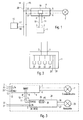
- Fig. 1 schematically an embodiment of the present invention is shown.
- the inventive system for data transmission comprises a device 1 with two output lines 2, 3, via which the device 1 can send a data signal.
- the number of output lines 2, 3 can be arbitrary. In particular, it is possible that more than two output lines 2, 3 are used, so that the device 1 can transmit, for example, parallel data streams.
- the output lines or interfaces 2, 3 may be analog and / or digital, which allows the transmission of an analog or digital data signal.
- the magnitude or amplitude of a transmitted analog data signal may vary continuously, taking any value between a certain maximum and a certain minimum.
- a modulation unit may be integrated in the device 1 to transmit modulated analogue source information.
- analog modulation are the amplitude modulation, the frequency modulation and the phase modulation, wherein in each case the amplitude, the frequency and the phase of a carrier signal, for example a sinusoidal voltage is modified by the source information.
- the device 1 can also send a digital signal via the output lines 2, 3.
- the source information is provided in this case as a discrete and quantized signal or sent. If the source information itself is discrete and quantized information, it can be readily used. In contrast, an analogue i. continuous source information to be digitized first. This digitization is e.g. from an analog-to-digital converter (not shown) made in the device 1 itself.
- the generated digital signal is advantageously also compressed and modulated by corresponding units.
- the source information transmitted as an analog or digital signal may be information of any nature. It may be, for example, a status information about the state of the device 1. In addition, this source information may originate from the device 1 itself or from an external unit. Fig. 2 shows how the device 1 can win this source information.
- the source information may be supplied, for example, from a measuring instrument 21, a sensor 22, a memory 23 or a processor 24, or may also be received via an additional interface 25, 26.
- the analog or digital data signal is connected to the output lines 2, 3 of the device 1 Lines 10, 11 an operating device 4 for lighting 7 supplied.
- the operating device 4 has a corresponding first interface 8, 9, which is also connected to the lines 10, 11. It is an analog or digital interface 8, 9, depending on whether an analog or a digital signal via the lines 10, 11 is transmitted.
- This first interface 8, 9 may be a sensor interface, in particular a so-called interface for an active or passive light sensor.
- a sensor interface may e.g. be connected to light sensors to control the brightness of the lamp 7.
- the brightness of the lamp environment measured by the light sensor is fed via the first interface 8, 9 to a control device 19 of the operating device 4, wherein the control device 19 can then regulate the lamp brightness.
- the operating device 4 is suitable for operating one or more lamps 7, in particular light-emitting diodes or fluorescent lamps such as, for example, gas discharge lamps.
- the second interface 12, 13 of the operating device 4 may preferably be constructed as a DSI (Digital Signal Interface), DALI (Digital Addressable Lighting Interface) or DMX (Digital Multiplex) interface. Such interfaces support appropriate control protocols for controlling the operating device 4 or for controlling and / or dimming the lamp 7. About this second interface 12, 13 according to the appropriate protocol certain dimming setpoints for the lamp 7 are supplied, so that the brightness of Lamp 7 can be determined according to these dimming setpoints by the control device 19.
- DSI Digital Signal Interface
- DALI Digital Addressable Lighting Interface
- DMX Digital Multiplex
- the operating device 4 is connected by means of the second interface 12, 13 to two lines 14, 15 of a bus 20.
- the bus 20 preferably connects a plurality of operating devices 4 and at least one central unit 16, which in turn is connected to the bus 20 via a corresponding interface 17, 18.
- Data may be transferred between the various nodes connected to the bus 20. Accordingly, two operating devices 4 or two central units 16 can communicate with each other. An operating device 4 can also exchange data with a central unit 16 via the bus 20.
- the operating device 4 forward the data received from the device 1 via the bus 20 so that the central unit 16 connected to the bus can recover the source information sent by the device 1 by reading the bus data.
- the addressing of data via the bus 20 can be implemented, for example, such that the data transmitted by the operating device 4 to the bus 20 data are sent as data packets, each data packet in addition to the source information sent from the device 1 additionally a related to the central unit 16 receiver Contains address. All connected nodes receive the data packets and read the receiver field of the data packets, but only the central unit 16 recognizes its address and will then also read and process the source information contained in the data packets.
- a data packet can also have additional fields, such as the transmitter address of the operating device 4.
- the address and / or name of the device 1 from which the source information originates can also be described .
- the central unit 16 via the bus 20, the source information also query or read directly at the operating unit 4: on a query of the central unit 16, the operating unit 4 responds with the transmission of the source information on the bus 20, so that the central unit 16 receive this source information can.
- Fig. 3 shows a particular embodiment of the present invention, in which the device 1 is an emergency lighting device 30.
- any device with a potential-free contact to the first interface 8, 9 of the operating device 4 may be connected.
- Particularly interesting are devices that can be installed in a luminaire itself. Examples of such devices are motion detectors, emergency lighting devices 30, smoke detectors or infrared receivers.
- FIG. 3 This in Fig. 3 shown system now uses an emergency light device 30, which is connected via an interface 36, 37 with an emergency light 35.
- the emergency light device 30 is connected to power lines 33, 34.
- the emergency lighting device 30 also has a status display 38 with at least one light emitting diode 39, 40 or LED (Light Emitting Diode) for displaying the status / state of the device 30.
- a status display 38 includes one or two status LEDs 39, 40, wherein the lighting, Flashing or flashing the respective status LEDs 39, 40 describes the status of the emergency light device 30. This status refers to e.g. on whether the battery charge of the emergency device 30 or the emergency light 35 is defective, or if there is a power failure.
- the status display 38 has two colored light-emitting diodes 39, 40.
- the green LED 39 signals a proper operation and the red LED 40 a lamp error.
- the performance of a test is indicated by flashing the green LED 39, while a fast flashing red LED 40 indicates a battery failure.
- an acoustic reproduction unit (not shown) can also reproduce the status information in an acoustically coded manner.
- the status LEDs 39, 40, or the electronics can be tested. This check is made independently by the emergency light device 30 and the result is signaled via the status display 38.
- the emergency light device 30 or generally the device 1 may be capable of autonomously performing a self-test at regular intervals with regard to its performance or even for the detection of errors. For example, self-tests can be done weekly or annually, checking in particular the condition of the battery, the condition of the emergency light or the state of charge. The self-tests can also be bump tests or endurance tests.
- test button 46 see Fig. 5 to be connected to the emergency light device 30 or device 1 via a push-button connection 47. With this test button 46 it is then possible for a user to trigger a test of the emergency light device 30.
- the invention now proposes to connect the status LEDs 39, 40 to the first interface 8, 9 of the operating device 4. As soon as an error with respect to the battery charge or the status LEDs 39, 40 is detected, this is communicated to the operating device 4 via the lines 10, 11. This message can then be forwarded via the bus 20 to the central unit 16, as already described above.
- the status LEDs 39, 40 are connected to a first analog or digital interface 8, 9 in the form of an input for a passive or active sensor, in particular a light sensor. If an error is detected during self-monitoring of the emergency lighting device 30, the input 8, 9 of the operating device 4 is short-circuited. This error can finally be queried via the DALI bus 20.
- no interface of the emergency device 30 is used for the communication between the device 1 or emergency device 30 and the operating device 4.
- the operating device 4 is rather designed to recognize the status information of the emergency light device 30. This can be done, for example, by optical scanning of the status LEDs 39, 40, by optically monitoring the main light source 35 of the emergency lighting device 30 or alternatively by directly wiring the connections for the status LED 39, 40 to the first interface 8, 9, for example in FIG Form of sensor connections, the control gear 4 done.
- the first possibility for detecting the status information thus provides for optical scanning of the status LEDs 39, 40, which can be performed directly via a light sensor 45 on the first interface 8, 9 of the operating device 4, see Fig. 5 , For example, then a slow flashing of the red LED 40 can be detected by the operating device 4 and recorded and evaluated according to the described embodiment as a battery error.
- the emergency light 35 of the emergency light device 30 can also be monitored with the light sensor.
- This solution is particularly advantageous in emergency lighting operating devices which operate a light-emitting diode as an emergency light source, since a light-emitting diode is very difficult to detect a possible defect by monitoring the electrical operating parameters.
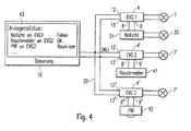
- Fig. 4 shows further embodiments and applications of the present invention.
- This in Fig. 4 System shown comprises three operating devices 4, 4 ', 4 "for controlling corresponding lamps 7, 7', 7".
- the operating devices 4, 4 ', 4 "and the central unit 16 are connected to the bus 20, so that these bus nodes can communicate with each other.
- the first operating device 4 is connected via its first interface 8, 9 with an emergency lighting device 31 according to Fig. 3 connected.
- the second and third operating devices 4 ', 4 "are each connected via their first interface 8', 9 'and 8", 9 '' connected to a smoke detector 41 and a motion detector 42.
- the smoke detector 41 may announce an internal fault of the electronics or the smoke sensor via the digital input 8 ', 9' of the second dimmable operating device 4 'and via the bus 20 of the central unit 16. Not only status information of the smoke detector 41 can be sent to the central unit 16, but also a smoke alarm.
- the central unit 16 is capable of collecting information about various devices 31, 41, 42 connected to operating devices 4, 4 ', 4 ", processing them and possibly displaying them to a user 43. Monitoring of the devices 31, 41, 42 is simplified. the user no longer has to individually check and interpret the status LEDs 39, 40 of the devices, however, with the system according to the invention he can directly read the information directly on the display 43.
- each operating device is assigned a unique address, so that a communication between these units via the bus 20 is possible.
- the additional devices 31, 41, 42 need no unique address, since these devices 31, 41, 42 of the respective operating device 4, 4 ', 4''quasi monitored as a sub-master.
- the error messages or status messages of the emergency light device 31, the smoke detector 41 or the motion detector 42 can be sent using a separate error log, so that the operating device 4 and the central unit 16 different errors or states of the connected to the operating device 4 device 31, 41, 42 easy and fast to recognize.
- the emergency light device 30 or device 1 can be dispensed with a communication interface in order to transmit data such as, for example, status information to the bus-compatible operating device 4.
- This unidirectional communication takes place by optical scanning or monitoring of the status LEDs 39, 40 or the emergency light 35 of the emergency light device 30, or by wiring the connections for status LEDs 39, 40 with the sensor port 8, 9 of the operating device 4th
- the operating device 4 can according to a pulse train, which transmits it via a wiring to the emergency light device 30, a self-test of the emergency device 30 via, for example, the state of Battery, the lamp or the charge initiate. Thereupon, the operating device 4 can check on the basis of the signaling of the emergency light device 30 whether an error or problem exists.
- an embodiment of this bidirectional communication can provide that pulses or data for initiating a test are first sent via the connections 8, 9 of the operating device 4, and that then the same connections 8, 9 are switched over to the monitoring of the emergency light device 30.
- signaling may be provided by the operating device 4 to a terminal of the emergency lighting device 30, e.g. to the probe connector 47 for the test button 46, a test of the emergency device 30 are triggered.
- the information for starting a self-test can not be sent to the status connection 8, 9, since such a status connection 8, 9 is generally connected by diode only to transmission incl. LED operation.
- the operating device 4 monitors the behavior of the emergency light device 30 with the aid of the light sensor 45.
- the behavior of the status light-emitting diodes 39, 40 or the emergency light 35 can be monitored, as already described above.
- the operating device 4 an additional control output 48 for driving the emergency light device 30 has. But it can also be switched by switching the operating mode of the sensor port 8, 9 of the operating device 4 from a transmission mode to a monitoring mode, see Fig. 7 ,
- the sensor connection 8, 9 of the operating device 4 can be reprogrammed, for example via its bus-capable interface 12, 13, so that this sensor connection 8, 9 is not used as brightness monitoring but to monitor the status of another operating device.
Landscapes
- Alarm Systems (AREA)
- Circuit Arrangement For Electric Light Sources In General (AREA)
- Fire Alarms (AREA)
- Selective Calling Equipment (AREA)
Applications Claiming Priority (1)
| Application Number | Priority Date | Filing Date | Title |
|---|---|---|---|
| DE102007004397.1A DE102007004397B4 (de) | 2007-01-29 | 2007-01-29 | Verfahren und System zur Datenübertragung |
Publications (1)
| Publication Number | Publication Date |
|---|---|
| EP1954105A1 true EP1954105A1 (fr) | 2008-08-06 |
Family
ID=38486947
Family Applications (1)
| Application Number | Title | Priority Date | Filing Date |
|---|---|---|---|
| EP08100407A Ceased EP1954105A1 (fr) | 2007-01-29 | 2008-01-14 | Procédé et système de transmission de données dans des appareils de fonctionnement pour moyens d'éclairage |
Country Status (2)
| Country | Link |
|---|---|
| EP (1) | EP1954105A1 (fr) |
| DE (1) | DE102007004397B4 (fr) |
Cited By (8)
| Publication number | Priority date | Publication date | Assignee | Title |
|---|---|---|---|---|
| DE102008034524A1 (de) * | 2008-07-24 | 2010-01-28 | Tridonicatco Gmbh & Co. Kg | Notlichteinheit |
| WO2010012417A1 (fr) * | 2008-07-29 | 2010-02-04 | Tridonicatco Gmbh & Co. Kg | Attribution d'une adresse de service à un appareil de service pour moyens d'éclairement à commande par bus |
| DE102009032026A1 (de) * | 2009-07-07 | 2011-01-13 | Tridonicatco Gmbh & Co. Kg | Betriebsgerät für Leuchtmittel |
| EP2421120A3 (fr) * | 2010-08-17 | 2014-03-19 | Zumtobel Lighting GmbH | Dispositif de surveillance de la tension d'une alimentation électrique avec connexion à un bus |
| WO2017085182A1 (fr) * | 2015-11-17 | 2017-05-26 | Tridonic Gmbh & Co Kg | Appareil ballast pour moyen d'éclairage avec microprocesseur et interface de programmation |
| DE202016006286U1 (de) | 2016-10-10 | 2018-01-12 | Tridonic Gmbh & Co. Kg | Betriebsgerät für Leuchtmittel mit Ausgabe von Statusinformation insbesondere zur Fehleranalyse |
| DE202016007323U1 (de) * | 2016-11-30 | 2018-03-02 | Tridonic Gmbh & Co. Kg | Betriebsgerät mit Testschalter und Statusanzeige |
| EP3391713B1 (fr) | 2016-06-13 | 2020-08-12 | Zumtobel Lighting GmbH | Protocolisation décentralisé des états de fonctionnement de composants de la technique du bâtiment |
Families Citing this family (5)
| Publication number | Priority date | Publication date | Assignee | Title |
|---|---|---|---|---|
| DE102009034111B4 (de) | 2008-07-28 | 2022-01-05 | Tridonic Gmbh & Co Kg | Beleuchtungssystem und Verfahren zur Steuerung eines Beleuchtungssystems |
| DE102010052663B4 (de) * | 2010-11-26 | 2016-03-10 | Abb Ag | Übertragungssystem zur Übertragung von Datentelegrammen über eine Lastleitung |
| DE102012218429A1 (de) | 2012-10-10 | 2014-04-10 | Zumtobel Lighting Gmbh | System zur Funktionsüberwachung einer Stromschleife |
| DE202014105984U1 (de) * | 2014-12-11 | 2016-03-14 | Tridonic Gmbh & Co Kg | Betriebsgerät zum Betreiben von Leuchtmitteln |
| DE102016212108A1 (de) * | 2016-07-04 | 2018-01-04 | Zumtobel Lighting Gmbh | Beleuchtungssystem mit ortsbezogener Messwerterfassung |
Citations (10)
| Publication number | Priority date | Publication date | Assignee | Title |
|---|---|---|---|---|
| EP0415662A2 (fr) * | 1989-08-29 | 1991-03-06 | Teknoware Oy | Dispositif pour surveiller l'état d'un système d'éclairage de sécurité |
| EP1071054A2 (fr) * | 1996-10-25 | 2001-01-24 | Hubbell Incorporated | Lentille pour un détecteur de mouvement |
| GB2365231A (en) * | 2000-06-27 | 2002-02-13 | Paul Mans | Method and apparatus for the control of lighting circuits |
| WO2003094579A2 (fr) * | 2002-04-30 | 2003-11-13 | Environmental Management Limited | Systeme de commande electrique |
| US20030222603A1 (en) * | 2002-06-03 | 2003-12-04 | Systel Development & Industries Ltd | Multiple channel ballast and networkable topology and system including power line carrier applications |
| US20040217718A1 (en) * | 2003-05-02 | 2004-11-04 | Russikesh Kumar | Digital addressable electronic ballast and control unit |
| GB2404474A (en) * | 2003-07-29 | 2005-02-02 | Cooper Lighting And Security L | Emergency lighting monitoring system with lighting control |
| US20050179404A1 (en) * | 2004-02-13 | 2005-08-18 | Dragan Veskovic | Multiple-input electronic ballast with processor |
| EP1619935A2 (fr) * | 2004-07-22 | 2006-01-25 | Patent -Treuhand-Gesellschaft für elektrische Glühlampen mbH | Element lumineux de secours avec interface de commande numérique |
| WO2007009896A1 (fr) * | 2005-07-21 | 2007-01-25 | Siemens Aktiengesellschaft | Procede de detection de l'appartenance d'un dispositif d'alimentation d'eclairage de secours a un ballast electronique dans un reseau dali |
Family Cites Families (1)
| Publication number | Priority date | Publication date | Assignee | Title |
|---|---|---|---|---|
| IES990284A2 (en) | 1998-04-09 | 1999-09-22 | Power Standby Systems Ltd | An emergency lighting network |
-
2007
- 2007-01-29 DE DE102007004397.1A patent/DE102007004397B4/de not_active Expired - Fee Related
-
2008
- 2008-01-14 EP EP08100407A patent/EP1954105A1/fr not_active Ceased
Patent Citations (10)
| Publication number | Priority date | Publication date | Assignee | Title |
|---|---|---|---|---|
| EP0415662A2 (fr) * | 1989-08-29 | 1991-03-06 | Teknoware Oy | Dispositif pour surveiller l'état d'un système d'éclairage de sécurité |
| EP1071054A2 (fr) * | 1996-10-25 | 2001-01-24 | Hubbell Incorporated | Lentille pour un détecteur de mouvement |
| GB2365231A (en) * | 2000-06-27 | 2002-02-13 | Paul Mans | Method and apparatus for the control of lighting circuits |
| WO2003094579A2 (fr) * | 2002-04-30 | 2003-11-13 | Environmental Management Limited | Systeme de commande electrique |
| US20030222603A1 (en) * | 2002-06-03 | 2003-12-04 | Systel Development & Industries Ltd | Multiple channel ballast and networkable topology and system including power line carrier applications |
| US20040217718A1 (en) * | 2003-05-02 | 2004-11-04 | Russikesh Kumar | Digital addressable electronic ballast and control unit |
| GB2404474A (en) * | 2003-07-29 | 2005-02-02 | Cooper Lighting And Security L | Emergency lighting monitoring system with lighting control |
| US20050179404A1 (en) * | 2004-02-13 | 2005-08-18 | Dragan Veskovic | Multiple-input electronic ballast with processor |
| EP1619935A2 (fr) * | 2004-07-22 | 2006-01-25 | Patent -Treuhand-Gesellschaft für elektrische Glühlampen mbH | Element lumineux de secours avec interface de commande numérique |
| WO2007009896A1 (fr) * | 2005-07-21 | 2007-01-25 | Siemens Aktiengesellschaft | Procede de detection de l'appartenance d'un dispositif d'alimentation d'eclairage de secours a un ballast electronique dans un reseau dali |
Non-Patent Citations (2)
| Title |
|---|
| "ONLITE EMERGENCY LIGHTING", 31 March 2004, XP002351214 * |
| ALONSO J M ET AL: "A smart-lighting emergency ballast for fluorescent lamps based on microcontroller", PROCEEDINGS OF THE ANNUAL APPLIED POWER ELECTRONICS CONFERENCE AND EXPOSITION (APEC). SAN DIEGO, MAR. 7 - 11, 1993, NEW YORK, IEEE, US, vol. CONF. 8, 7 March 1993 (1993-03-07), pages 549 - 555, XP010111283, ISBN: 0-7803-0983-9 * |
Cited By (15)
| Publication number | Priority date | Publication date | Assignee | Title |
|---|---|---|---|---|
| DE102008034524B4 (de) | 2008-07-24 | 2019-12-05 | Tridonic Gmbh & Co Kg | Notlichteinheit |
| DE102008034524A1 (de) * | 2008-07-24 | 2010-01-28 | Tridonicatco Gmbh & Co. Kg | Notlichteinheit |
| WO2010012417A1 (fr) * | 2008-07-29 | 2010-02-04 | Tridonicatco Gmbh & Co. Kg | Attribution d'une adresse de service à un appareil de service pour moyens d'éclairement à commande par bus |
| DE102009032026A1 (de) * | 2009-07-07 | 2011-01-13 | Tridonicatco Gmbh & Co. Kg | Betriebsgerät für Leuchtmittel |
| EP2421120A3 (fr) * | 2010-08-17 | 2014-03-19 | Zumtobel Lighting GmbH | Dispositif de surveillance de la tension d'une alimentation électrique avec connexion à un bus |
| AT16920U1 (de) * | 2015-11-17 | 2020-12-15 | Tridonic Gmbh & Co Kg | Vorschaltgerät für Leuchtmittel mit Mikroprozessor und Programmierungsschnittstelle |
| WO2017085182A1 (fr) * | 2015-11-17 | 2017-05-26 | Tridonic Gmbh & Co Kg | Appareil ballast pour moyen d'éclairage avec microprocesseur et interface de programmation |
| EP4355033A3 (fr) * | 2015-11-17 | 2024-05-29 | Tridonic GmbH & Co. KG | Composant pour un système d'éclairage à microprocesseur et interface de programmation |
| EP3955705A1 (fr) * | 2015-11-17 | 2022-02-16 | Tridonic GmbH & Co. KG | Composant pour un système d'éclairage pourvu de microprocesseur et interface de programmation |
| US10257912B2 (en) | 2015-11-17 | 2019-04-09 | Tridonic Gmbh & Co Kg | Ballast for luminous means having a microprocessor and a programming interface |
| EP3391713B1 (fr) | 2016-06-13 | 2020-08-12 | Zumtobel Lighting GmbH | Protocolisation décentralisé des états de fonctionnement de composants de la technique du bâtiment |
| EP3307023B1 (fr) * | 2016-10-10 | 2023-08-16 | Tridonic GmbH & Co. KG | Appareil de fonctionnement pour lampe pourvu de sortie des informations d'état, en particulier d'analyse des erreurs |
| DE202016006286U1 (de) | 2016-10-10 | 2018-01-12 | Tridonic Gmbh & Co. Kg | Betriebsgerät für Leuchtmittel mit Ausgabe von Statusinformation insbesondere zur Fehleranalyse |
| US10757780B2 (en) | 2016-11-30 | 2020-08-25 | Tridonic Gmbh & Co Kg | Operating device having a test switch and status indicator |
| DE202016007323U1 (de) * | 2016-11-30 | 2018-03-02 | Tridonic Gmbh & Co. Kg | Betriebsgerät mit Testschalter und Statusanzeige |
Also Published As
| Publication number | Publication date |
|---|---|
| DE102007004397B4 (de) | 2019-06-13 |
| DE102007004397A1 (de) | 2008-07-31 |
Similar Documents
| Publication | Publication Date | Title |
|---|---|---|
| DE102007004397B4 (de) | Verfahren und System zur Datenübertragung | |
| EP2182776A1 (fr) | Lampe de signalisation dotée d'une unité de socle et d'au moins une unité d'éclairage | |
| DE102006046489A1 (de) | Betriebsgerät und Verfahren zum Betreiben von Leuchtmitteln | |
| WO2019166500A1 (fr) | Procédé et dispositif de commande de composants électriques et/ou électroniques d'un module de véhicule à moteur | |
| EP2553674B1 (fr) | Procédé d'éclairage d'un caisson lumineux | |
| WO2009065522A1 (fr) | Dispositif de fonctionnement pour moyens d'éclairage pour sortie de données | |
| EP1891838B1 (fr) | Determination de l'adresse de bus d'un element connecte dans un systeme de bus d'eclairage | |
| EP3944565A1 (fr) | Système et procédé d'établissement d'une connexion de données selon la norme io-link entre une unité maîtrisasse et au moins un appareil dispositif | |
| DE102010042724A1 (de) | Gerät für eine Lampenanwendung und Verfahren zur Ansteuerung des Geräts | |
| WO2010043263A1 (fr) | Dispositif d’interface pour un circuit de commande de lumière dali et procédé pour sa surveillance | |
| DE102018104872A1 (de) | Verfahren zur Ansteuerung elektrischer und/oder elektronischer Komponenten eines Kfz-Moduls und ein derartiges Kfz-Modul mit automatischer Moduladressierung über Powerline | |
| DE102018104864B3 (de) | Vorrichtung zur Ansteuerung elektrischer und/oder elektronischer Komponenten eines Kfz-Moduls und ein derartiges Kfz-Modul mit automatischer Moduladressierung mit Taktsynchronisation und Adressierungsmodussignalisierung | |
| EP2545683B1 (fr) | Système d'éclairage comprenant des équipements maîtres/esclaves pour des moyens d'éclairage | |
| DE102018104866B3 (de) | Vorrichtung zur Ansteuerung elektrischer und/oder elektronischer Komponenten eines Kfz-Moduls und ein derartiges Kfz-Modul mit automatischer Moduladressierung | |
| EP4216184B1 (fr) | Système d'alerte | |
| EP3253181B1 (fr) | Procédé pour la communication de données entre un module d'émission/réception et un module led comprenant au moins une led ou entre un module d'émission/réception et des modules led dans un branchement en série de plusieurs modules led, comprenant chacun au moins une led | |
| AT507128B1 (de) | Verfahren zur ansteuerung für ein betriebsgerät für leuchtmittel | |
| WO2015143469A1 (fr) | Procédé de commande d'un appareil destiné à faire fonctionner des moyens d'éclairage | |
| EP3934387B1 (fr) | Dispositif à connexion multifonctionnelle pour appareils de commande non dali | |
| EP3376485A1 (fr) | Unité d'émission de signal à canal de retour intégré | |
| DE102018104847A1 (de) | Verfahren zur Ansteuerung elektrischer und/oder elektronischer Komponenten eines Kfz-Moduls und ein derartiges Kfz-Modul mit automatischer Moduladressierung mittels Daisy-Chain | |
| DE102018104862A1 (de) | Vorrichtung zur Ansteuerung elektrischer und/oder elektronischer Komponenten eines Kfz-Moduls und ein derartiges Kfz-Modul mit automatischer Moduladressierung und Bus-Shunt-Überbrückungsschaltern | |
| DE102007053793A1 (de) | Leuchtmittel-Betriebsgerät mit Schnittstelle | |
| WO2011103611A2 (fr) | Procédé d'éclairage d'un caisson lumineux | |
| EP3741191B1 (fr) | Appareil pour un réseau d'éclairage avec une alimentation décentralisée |
Legal Events
| Date | Code | Title | Description |
|---|---|---|---|
| PUAI | Public reference made under article 153(3) epc to a published international application that has entered the european phase |
Free format text: ORIGINAL CODE: 0009012 |
|
| AK | Designated contracting states |
Kind code of ref document: A1 Designated state(s): AT BE BG CH CY CZ DE DK EE ES FI FR GB GR HR HU IE IS IT LI LT LU LV MC MT NL NO PL PT RO SE SI SK TR |
|
| AX | Request for extension of the european patent |
Extension state: AL BA MK RS |
|
| 17P | Request for examination filed |
Effective date: 20090112 |
|
| AKX | Designation fees paid |
Designated state(s): AT BE BG CH CY CZ DE DK EE ES FI FR GB GR HR HU IE IS IT LI LT LU LV MC MT NL NO PL PT RO SE SI SK TR |
|
| RAP1 | Party data changed (applicant data changed or rights of an application transferred) |
Owner name: TRIDONIC GMBH & CO KG |
|
| 17Q | First examination report despatched |
Effective date: 20100924 |
|
| STAA | Information on the status of an ep patent application or granted ep patent |
Free format text: STATUS: THE APPLICATION HAS BEEN REFUSED |
|
| 18R | Application refused |
Effective date: 20141120 |