EP1955896A2 - Fahrzeugspiegelvorrichtung - Google Patents
Fahrzeugspiegelvorrichtung Download PDFInfo
- Publication number
- EP1955896A2 EP1955896A2 EP08001201A EP08001201A EP1955896A2 EP 1955896 A2 EP1955896 A2 EP 1955896A2 EP 08001201 A EP08001201 A EP 08001201A EP 08001201 A EP08001201 A EP 08001201A EP 1955896 A2 EP1955896 A2 EP 1955896A2
- Authority
- EP
- European Patent Office
- Prior art keywords
- motor
- circuit
- transistor
- battery voltage
- unit
- Prior art date
- Legal status (The legal status is an assumption and is not a legal conclusion. Google has not performed a legal analysis and makes no representation as to the accuracy of the status listed.)
- Granted
Links
Images


Classifications
-
- B—PERFORMING OPERATIONS; TRANSPORTING
- B60—VEHICLES IN GENERAL
- B60R—VEHICLES, VEHICLE FITTINGS, OR VEHICLE PARTS, NOT OTHERWISE PROVIDED FOR
- B60R1/00—Optical viewing arrangements; Real-time viewing arrangements for drivers or passengers using optical image capturing systems, e.g. cameras or video systems specially adapted for use in or on vehicles
- B60R1/02—Rear-view mirror arrangements
- B60R1/06—Rear-view mirror arrangements mounted on vehicle exterior
- B60R1/062—Rear-view mirror arrangements mounted on vehicle exterior with remote control for adjusting position
- B60R1/07—Rear-view mirror arrangements mounted on vehicle exterior with remote control for adjusting position by electrically powered actuators
- B60R1/074—Rear-view mirror arrangements mounted on vehicle exterior with remote control for adjusting position by electrically powered actuators for retracting the mirror arrangements to a non-use position alongside the vehicle
-
- H—ELECTRICITY
- H02—GENERATION; CONVERSION OR DISTRIBUTION OF ELECTRIC POWER
- H02P—CONTROL OR REGULATION OF ELECTRIC MOTORS, ELECTRIC GENERATORS OR DYNAMO-ELECTRIC CONVERTERS; CONTROLLING TRANSFORMERS, REACTORS OR CHOKE COILS
- H02P3/00—Arrangements for stopping or slowing electric motors, generators, or dynamo-electric converters
- H02P3/06—Arrangements for stopping or slowing electric motors, generators, or dynamo-electric converters for stopping or slowing an individual dynamo-electric motor or dynamo-electric converter
-
- H—ELECTRICITY
- H02—GENERATION; CONVERSION OR DISTRIBUTION OF ELECTRIC POWER
- H02P—CONTROL OR REGULATION OF ELECTRIC MOTORS, ELECTRIC GENERATORS OR DYNAMO-ELECTRIC CONVERTERS; CONTROLLING TRANSFORMERS, REACTORS OR CHOKE COILS
- H02P2205/00—Indexing scheme relating to controlling arrangements characterised by the control loops
- H02P2205/01—Current loop, i.e. comparison of the motor current with a current reference
Definitions
- the present invention relates to a technology for controlling a current supply to a motor of a vehicle mirror device.
- a vehicle mirror device is a device that turns a mirror unit, which includes a mirror, to a predetermined position by using a drive motor.
- a mirror unit which includes a mirror
- a drive motor When the mirror unit has turned to a predetermined position and has stopped rotating, sometimes an overcurrent flows in the drive motor because of overloads.
- an overcurrent flows in the motor, a current supply to the motor is immediately cut OFF to prevent the motor from being damaged.
- Japanese Patent Application Laid-open No. 2002-127824 discloses a conventional technology for controlling a vehicle mirror device (an electrically-retractable door mirror).
- the conventional vehicle mirror device is configured to turn a door mirror of a vehicle any position between two predetermined positions, i.e., a stretched position and a retracted position.
- the vehicle mirror device includes a drive motor, a switch, a time constant circuit, a first circuit, and a second circuit.
- the drive motor is driven to turn the door mirror to any position between the stretched position and the retracted position.
- the switch includes a first output terminal and a second output terminal. The switch switches over a polarity of a direct-current power supply, and is operated to supply a direct-current voltage to the drive motor.
- the time constant circuit is arranged between the switch and the drive motor.
- the first circuit is arranged between the first output terminal of the switch and one terminal of the drive motor.
- the second circuit is arranged between the second output terminal of the switch and the other terminal of the drive motor.
- Each of the first circuit and the second circuit includes an electronic switch, an overcurrent detecting unit, and a breaking switch.
- the electronic switch is switched ON/OFF in response to an electric signal output from the time constant circuit.
- the overcurrent detecting unit has a characteristic such that its resistance value increases depending on a current value flowing therein, and is series-connected to the electronic switch.
- the breaking switch turns OFF the electronic switch when a voltage value generated by the overcurrent detecting unit exceeds a predetermined threshold.
- an electric current flowing in the drive motor is cut OFF when the current exceeds a fixed threshold. Because of this configuration, when a high battery voltage is applied to the drive motor, the current supply to the drive motor is cut OFF at the fixed threshold, although the drive motor can be further rotated.
- a vehicle mirror device including a base unit that is configured to be attached to a vehicle; a mirror unit that includes a mirror and that is mounted on the base unit in a turnable manner with respect to the base unit; and a driving unit that turns the mirror unit with respect to the base unit, the driving unit including a motor that drives the mirror unit with a battery voltage; and a control circuit that cuts OFF a current supply to the motor when an electric current flowing in the motor exceeds a threshold, and the control circuit changes the threshold depending on the battery voltage.
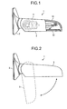
- Fig. 1 is a schematic diagram of a vehicle mirror device 1 according to an embodiment of the present invention.
- Fig. 2 is a schematic diagram for explaining operation of stretching and retracting the vehicle mirror device 1.
- Fig. 3 is a block diagram of a driving unit 4 shown in Fig. 1 .
- the vehicle mirror device 1 can be attached to a vehicle (not shown) as an electrically-retractable door mirror (outside mirror).
- the vehicle mirror device 1 includes a base unit 2, a mirror unit 3, and the driving unit 4.
- the base unit 2 is configured to be attached to a door (not shown) of the vehicle.
- the mirror unit 3 includes a mirror housing 31 and a mirror 32 that is housed inside the mirror housing 31.
- the mirror unit 3 is mounted on the base unit 2 in a turnable manner with respect to the base unit 2, as shown in Fig. 2 .
- the driving unit 4 is configured to turn the mirror unit 3 with respect to the base unit 2, and it is also housed inside the mirror housing 31.
- the driving unit 4 includes a control circuit 41 and a driving mechanism 42.
- the control circuit 41 is configured to control the driving mechanism 42, and it is connected to a vehicle battery (not shown) that is a direct-current power supply.
- the control circuit 41 will be described in detail later.
- the driving mechanism 42 includes a motor 421 and a plurality of gears (not shown) that is connected to the motor 421.
- the motor 421 is driven with a battery voltage applied from a vehicle battery. A torque of the motor 421 is transmitted to the mirror unit 3 through the gears, so that the mirror unit 3 is turned with respect to the base unit 2.
- the mirror unit 3 can be turned to any position between a predetermined stretched position and a predetermined retracted position including both of those positions.
- the driver of the vehicle can see the mirror 32 from inside the vehicle.
- the driving unit 4 is driven by operating a switch (not shown) arranged in a vehicle.
- the driving unit 4 is driven by operating the switch.
- the control circuit 41 includes a voltage detecting circuit 411, a shunt circuit 412, a current detecting circuit 413, a comparison control circuit 414, and a switch circuit 415.
- the voltage detecting circuit 411 detects a battery voltage applied from a battery (a voltage to be applied to the motor 421).
- the shunt circuit 412 converts a motor current (an electric current flowing in the motor 421) into a voltage.
- the current detecting circuit 413 detects the motor current via the shunt circuit 412.
- the comparison control circuit 414 compares the battery voltage detected by the voltage detecting circuit 411 with the motor current detected by the current detecting circuit 413, and generates an output signal indicative of the result of the comparison.
- the switch circuit 415 turns ON/OFF a current supply to the motor 421 based on the output signal.
- Fig. 4 is a flowchart of operation performed by the control circuit 41.
- the switch circuit 415 is driven to turn ON the current supply to the motor 421, so that the battery voltage is applied to the motor 421.
- the voltage detecting circuit 411 detects the battery voltage (step ST1), and the comparison control circuit 414 receives the battery voltage detected by the voltage detecting circuit 411. Meanwhile, when the motor 421 is locked due to overloads, an overcurrent flows in the motor 421.
- the current detecting circuit 413 detects the overcurrent, and determines that as a motor current (step ST2).
- the comparison control circuit 414 receives the motor current detected by the current detecting circuit 413.
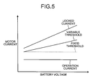
- Fig. 5 is a graph for explaining relation between a battery voltage and a threshold.
- An increase of a battery voltage causes an increase of a motor current (locked current) flowing in the motor 421 that is locked due to overloads.
- the motor 421 When a high battery voltage is applied to the motor 421, the motor 421 generates a higher torque, i.e., the motor 421 can be rotated with a higher motor current than that of when a low battery voltage is applied to the motor 421.
- the current supply to the motor 421 is cut OFF when the motor current exceeds a threshold, and the comparison control circuit 414 changes the threshold depending on the battery voltage.
- the threshold is increased in proportion to the battery voltage. In other words, a difference between an electric current flowing in the motor 421 during normal operation and the threshold increases in proportion to the battery voltage.
- the comparison control circuit 414 selects a threshold corresponding to a battery voltage (step ST3).
- the comparison control circuit 414 compares a motor current with the selected threshold (step ST4). When the motor current exceeds the threshold, the comparison control circuit 414 outputs an output signal that causes the switch circuit 415 to be driven to cut OFF the current supply to the motor 421 (step ST5). Thus, the motor 421 can be prevented from being damaged by the overcurrent.
- the current supply to the motor 421 is cut OFF based on a threshold that is determined depending on a battery voltage.
- a threshold that is determined depending on a battery voltage.
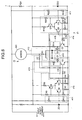
- Fig. 6 is an example of a circuitry of the control circuit 41.
- the control circuit 41 is configured as described below.
- the control circuit 41 includes two circuits, i.e., a retracting circuit adapted to set the mirror unit 3 to the retracted position and a stretching circuit adapted to set the mirror unit 3 to the stretched position.
- the retracting circuit and the stretching circuit are arranged symmetrically to each other. Operations of retracting and stretching the mirror unit 3 are selectively performed by switching over a connection of a vehicle battery to the retracting circuit or the stretching circuit.
- the retracting circuit (the stretching circuit) is configured as described below. It should be noted that a configuration of the stretching circuit is explained in parentheses as appropriate in the following description.
- the voltage detecting circuit 411 includes a resistor R11 and a resistor R12 (a resistor R22 and a resistor R23).
- the shunt circuit 412 includes a resistor R1.
- the current detecting circuit 413 includes a resistor R2, a resistor R5, and a capacitor C1 (the resistor R2, a resistor R16, and the capacitor C1) that are configured as a charge circuit.
- the comparison control circuit 414 includes resistors R4 to R10 and transistors Q2 to Q5 (resistors R15 to R21 and transistors Q7 to Q10).
- the switch circuit 415 includes a resistor R3 and a switching element Q1 (a resistor R14 and a switching element Q6).
- the reference marks D1, D2 denote a diode, R24 a resistor, and ZD1, ZD2 a Zener diode.
- a battery voltage is divided by the resistors R11 and R12 (the resistors R22 and R23), and is applied to a base of the transistor Q4 (the transistor Q9).
- a current flowing in the motor 421 is detected by the resistor R1, and is applied to a base of the transistor Q3 (the transistor Q8) through the resistor R2, the resistor R5, and the capacitor C1 (the resistor R2, the resistor R16, and the capacitor C1).
- the transistors Q3 to Q5 are configured as a differential amplifier circuit.
- the transistor Q3 When an electric potential applied to the base of the transistor Q3 (the transistor Q8) is lower (higher) than that to a base of the transistor Q4 (the transistor Q9), the transistor Q3 (the transistor Q8) is turned ON. Accordingly, the transistor Q4 (the transistor Q9) is turned OFF, and an electric potential applied to a collector of the transistor Q4 (the transistor Q9) becomes zero. Meanwhile, the transistor Q2 (the transistor Q7) is turned OFF, and the switching element Q1 (the switching element Q6) is turned ON.
- the comparison control circuit 414 includes a comparison circuit and a drive circuit.
- the comparison circuit includes the resistors R6 to R10 and the transistors Q3 to Q5 (the resistors R17 to R21 and the transistors Q8 to Q10).
- the comparison circuit is configured to compare the battery voltage with the motor current.
- the drive circuit includes the resistors R3, R4 and the transistor Q2 (the resistors R14, R15 and the transistor Q7).
- the drive circuit is configured to drive the switch circuit 415 based on a result of a comparison performed by the comparison circuit.
- the base of the transistor Q4 (the transistor Q9) (a first transistor) is connected to the voltage detecting circuit 411.
- the battery voltage is divided by the resistors R11, R12 (the resistors R22, R23), so that an electric potential is applied to the base of the transistor Q4 (the transistor Q9).
- an electric potential applied to the base of the transistor Q4 becomes higher (lower).
- the base of the transistor Q3 (the transistor Q8) (a second transistor) is connected to the current detecting circuit 413.
- an electric potential applied to the base of the transistor Q3 becomes higher (lower).
- Fig. 7 is another example of a circuitry of the control circuit 41.
- the control circuit 41 is configured as described below.
- the voltage detecting circuit 411 includes a resistor R20, a resistor R30, and a capacitor C3.
- the shunt circuit 412 includes a resistor R10.
- the current detecting circuit 413 includes a resistor R40 and a capacitor C2.
- the comparison control circuit 414 and the switch circuit 415 are configured as one circuit, and the circuit includes a control unit (microcomputer) M and a transistor Q10.
- a polarity inverting circuit 416 includes a transistor Q20. The polarity inverting circuit 416 switches a current supply to the motor 421 when switching over operations of retracting and stretching the mirror unit 3.
- the battery voltage is divided by the resistor R20 and the resistor R30, and is applied to an analog-to-digital input channel of the control unit M.
- the battery voltage is applied to the control unit M at a voltage division ratio depending on fluctuations of the battery voltage.
- the control unit M prepares thresholds corresponding to various battery voltages in advance.
- a motor current is converted into a voltage by a resistor R10, and applied to the control unit M.
- the control unit M selects a threshold corresponding to that battery voltage.
- the motor current is then compared with the selected threshold. When the motor current exceeds the threshold, the current supply to the motor 421 is cut OFF.
- the polarity inverting circuit 416 switches a connection between the control circuit 41 and the motor 421, so that operations of retracting and stretching the mirror unit 3 are switched over.
- a current supply to a motor is cut OFF based on a threshold that is determined depending on a battery voltage.
- a threshold that is determined depending on a battery voltage.
Landscapes
- Engineering & Computer Science (AREA)
- Multimedia (AREA)
- Mechanical Engineering (AREA)
- Power Engineering (AREA)
- Rear-View Mirror Devices That Are Mounted On The Exterior Of The Vehicle (AREA)
- Control Of Electric Motors In General (AREA)
- Control Of Direct Current Motors (AREA)
Applications Claiming Priority (1)
| Application Number | Priority Date | Filing Date | Title |
|---|---|---|---|
| JP2007026849A JP2008189183A (ja) | 2007-02-06 | 2007-02-06 | 車両用ミラー装置 |
Publications (4)
| Publication Number | Publication Date |
|---|---|
| EP1955896A2 true EP1955896A2 (de) | 2008-08-13 |
| EP1955896A3 EP1955896A3 (de) | 2010-12-01 |
| EP1955896B1 EP1955896B1 (de) | 2011-12-14 |
| EP1955896B8 EP1955896B8 (de) | 2012-03-14 |
Family
ID=39363972
Family Applications (1)
| Application Number | Title | Priority Date | Filing Date |
|---|---|---|---|
| EP08001201A Not-in-force EP1955896B8 (de) | 2007-02-06 | 2008-01-23 | Fahrzeugspiegelvorrichtung |
Country Status (5)
| Country | Link |
|---|---|
| US (1) | US7852024B2 (de) |
| EP (1) | EP1955896B8 (de) |
| JP (1) | JP2008189183A (de) |
| KR (1) | KR100923270B1 (de) |
| CN (1) | CN101242153A (de) |
Families Citing this family (10)
| Publication number | Priority date | Publication date | Assignee | Title |
|---|---|---|---|---|
| DE102007027898A1 (de) * | 2007-06-18 | 2008-12-24 | Robert Bosch Gmbh | Elektrowerkzeug mit Kaltstartfunktion |
| KR101106961B1 (ko) | 2009-10-22 | 2012-01-25 | 대한민국 | 공생균을 이용한 천마종자의 기내발아방법 |
| US8783883B2 (en) * | 2010-08-30 | 2014-07-22 | Honda Motor Co., Ltd. | Method for controlling power to a motor in a vehicle door mirror |
| KR101241169B1 (ko) * | 2011-10-11 | 2013-03-13 | 기아자동차주식회사 | 차량의 아웃사이드미러 제어방법 |
| KR101309841B1 (ko) * | 2011-12-29 | 2013-10-14 | 고재용 | 접이식 아웃사이드 미러의 모터 구동 장치 |
| DE102012215186A1 (de) * | 2012-08-27 | 2014-02-27 | Robert Bosch Gmbh | Batterie sowie Verfahren zum sicheren Betreiben der Batterie |
| US9216689B2 (en) | 2013-12-16 | 2015-12-22 | Honda Motor Co., Ltd. | Fail-safe mirror for side camera failure |
| CN107809197A (zh) * | 2017-11-23 | 2018-03-16 | 南宁市生润科技有限公司 | 一种船用电机控制的方法 |
| KR102463262B1 (ko) * | 2017-12-14 | 2022-11-10 | 주식회사 에스엘미러텍 | 차량용 미러 구동 제어 장치 및 방법 |
| CN109532577B (zh) * | 2018-12-24 | 2021-12-03 | 上海科世达-华阳汽车电器有限公司 | 一种电动座椅的防夹方法、装置以及电动座椅控制器 |
Citations (2)
| Publication number | Priority date | Publication date | Assignee | Title |
|---|---|---|---|---|
| JP2002127824A (ja) | 2000-10-20 | 2002-05-09 | Murakami Corp | 電動格納式ドアミラーの制御装置 |
| JP2007026849A (ja) | 2005-07-15 | 2007-02-01 | Seiko Epson Corp | エレクトロルミネッセンス装置、エレクトロルミネッセンス装置の製造方法および電子機器 |
Family Cites Families (12)
| Publication number | Priority date | Publication date | Assignee | Title |
|---|---|---|---|---|
| JPH0840146A (ja) * | 1994-08-03 | 1996-02-13 | Murakami Kaimeidou:Kk | 電動格納式ドアミラーの制御装置 |
| US5703732A (en) * | 1995-01-17 | 1997-12-30 | Lowell Engineering Corporation | Exterior mirror with indexing and control pivoting |
| JPH0995140A (ja) * | 1995-10-02 | 1997-04-08 | Oi Seisakusho Co Ltd | 車両用電動対象物の駆動制御装置 |
| US5952802A (en) * | 1997-12-08 | 1999-09-14 | Delco Electronics Corp. | Method of controlling an automotive mirror |
| WO2001022569A1 (en) * | 1999-09-20 | 2001-03-29 | Schefenacker Vision Systems Australia Pty Ltd | Direct current motor control circuit |
| JP2001328487A (ja) * | 2000-05-19 | 2001-11-27 | Murakami Corp | 電動格納式ドアミラーの制御装置 |
| JP3581838B2 (ja) | 2001-05-25 | 2004-10-27 | 株式会社村上開明堂 | 電動格納式ドアミラーの制御方式 |
| ES2188382B1 (es) * | 2001-06-11 | 2004-07-16 | Fico Mirrors S.A. | Mecanismo de abatimiento de un espejo retrovisor exterior. |
| JP2004274817A (ja) * | 2003-03-05 | 2004-09-30 | Yazaki Corp | モータ正転・逆転駆動回路 |
| DE502004001777D1 (de) * | 2003-08-08 | 2006-11-30 | Brose Fahrzeugteile | Steuereinrichtung und Verfahren zum Ansteuern eines abblendbaren Spiegels |
| JP2005193889A (ja) | 2003-12-12 | 2005-07-21 | Tokai Rika Co Ltd | ミラー装置用モータ制御回路 |
| JP2006290223A (ja) | 2005-04-13 | 2006-10-26 | Tokai Rika Co Ltd | 車両用電動ミラー装置 |
-
2007
- 2007-02-06 JP JP2007026849A patent/JP2008189183A/ja active Pending
- 2007-10-26 KR KR1020070108212A patent/KR100923270B1/ko not_active Expired - Fee Related
- 2007-12-10 CN CNA2007101933561A patent/CN101242153A/zh active Pending
-
2008
- 2008-01-10 US US11/972,112 patent/US7852024B2/en not_active Expired - Fee Related
- 2008-01-23 EP EP08001201A patent/EP1955896B8/de not_active Not-in-force
Patent Citations (2)
| Publication number | Priority date | Publication date | Assignee | Title |
|---|---|---|---|---|
| JP2002127824A (ja) | 2000-10-20 | 2002-05-09 | Murakami Corp | 電動格納式ドアミラーの制御装置 |
| JP2007026849A (ja) | 2005-07-15 | 2007-02-01 | Seiko Epson Corp | エレクトロルミネッセンス装置、エレクトロルミネッセンス装置の製造方法および電子機器 |
Also Published As
| Publication number | Publication date |
|---|---|
| EP1955896B1 (de) | 2011-12-14 |
| KR100923270B1 (ko) | 2009-10-23 |
| US7852024B2 (en) | 2010-12-14 |
| US20080186603A1 (en) | 2008-08-07 |
| EP1955896A3 (de) | 2010-12-01 |
| KR20080073627A (ko) | 2008-08-11 |
| EP1955896B8 (de) | 2012-03-14 |
| JP2008189183A (ja) | 2008-08-21 |
| CN101242153A (zh) | 2008-08-13 |
Similar Documents
| Publication | Publication Date | Title |
|---|---|---|
| EP1955896B1 (de) | Fahrzeugspiegelvorrichtung | |
| JP4278572B2 (ja) | 半導体スイッチの制御装置 | |
| JP2007049888A (ja) | モータ駆動装置及びこれを用いた電気機器 | |
| US20080247108A1 (en) | Load drive device | |
| JP2010158109A (ja) | 負荷回路の保護装置 | |
| US20200403397A1 (en) | Switching controller with adaptive overheating protection | |
| JP2011259096A (ja) | 負荷駆動回路装置及びこれを用いた電気機器 | |
| US7759892B2 (en) | Vehicle mirror device | |
| WO2010150488A1 (ja) | 電源保護回路およびそれを備えたモータ駆動装置 | |
| JP2009055754A (ja) | 保護回路 | |
| EP1696553B1 (de) | System zur generatorsteuerung für ein kraftfahrzeug | |
| EP2610109B1 (de) | Verfahren und Schaltkreis zur Erfassung der Blockierung eines Motors für elektrischen Klappspiegel | |
| JP2017073872A (ja) | チャージポンプ回路 | |
| JP3581838B2 (ja) | 電動格納式ドアミラーの制御方式 | |
| US9559622B2 (en) | Motor driving device, electronic appliance, and vehicle | |
| JP2020137137A (ja) | クランプ回路 | |
| JP3200278B2 (ja) | モータコントローラ | |
| JP3676168B2 (ja) | 電源供給制御装置 | |
| JP2007027465A (ja) | リニアソレノイドの駆動回路 | |
| JP5210710B2 (ja) | ゲート駆動装置 | |
| JP3632305B2 (ja) | モータ駆動装置 | |
| US20250309884A1 (en) | Switch device, load drive system, and switch system | |
| JP2010252469A (ja) | インバータ保護回路 | |
| JPH0947080A (ja) | モータコントローラ | |
| JP2024102598A (ja) | 半導体装置、電子機器、車両 |
Legal Events
| Date | Code | Title | Description |
|---|---|---|---|
| PUAI | Public reference made under article 153(3) epc to a published international application that has entered the european phase |
Free format text: ORIGINAL CODE: 0009012 |
|
| AK | Designated contracting states |
Kind code of ref document: A2 Designated state(s): AT BE BG CH CY CZ DE DK EE ES FI FR GB GR HR HU IE IS IT LI LT LU LV MC MT NL NO PL PT RO SE SI SK TR |
|
| AX | Request for extension of the european patent |
Extension state: AL BA MK RS |
|
| PUAL | Search report despatched |
Free format text: ORIGINAL CODE: 0009013 |
|
| AK | Designated contracting states |
Kind code of ref document: A3 Designated state(s): AT BE BG CH CY CZ DE DK EE ES FI FR GB GR HR HU IE IS IT LI LT LU LV MC MT NL NO PL PT RO SE SI SK TR |
|
| AX | Request for extension of the european patent |
Extension state: AL BA MK RS |
|
| RIC1 | Information provided on ipc code assigned before grant |
Ipc: B60R 1/00 20060101AFI20080519BHEP Ipc: H02P 3/06 20060101ALI20101026BHEP |
|
| 17P | Request for examination filed |
Effective date: 20110503 |
|
| GRAP | Despatch of communication of intention to grant a patent |
Free format text: ORIGINAL CODE: EPIDOSNIGR1 |
|
| RIC1 | Information provided on ipc code assigned before grant |
Ipc: H02P 3/06 20060101ALI20110601BHEP Ipc: B60R 1/00 20060101AFI20110601BHEP |
|
| AKX | Designation fees paid |
Designated state(s): AT BE BG CH CY CZ DE DK EE ES FI FR GB GR HR HU IE IS IT LI LT LU LV MC MT NL NO PL PT RO SE SI SK TR |
|
| AXX | Extension fees paid |
Extension state: MK Extension state: BA Extension state: AL Extension state: RS |
|
| GRAS | Grant fee paid |
Free format text: ORIGINAL CODE: EPIDOSNIGR3 |
|
| GRAA | (expected) grant |
Free format text: ORIGINAL CODE: 0009210 |
|
| RBV | Designated contracting states (corrected) |
Designated state(s): FR GB |
|
| AK | Designated contracting states |
Kind code of ref document: B1 Designated state(s): FR GB |
|
| REG | Reference to a national code |
Ref country code: GB Ref legal event code: FG4D |
|
| RBV | Designated contracting states (corrected) |
Designated state(s): DE FR GB |
|
| REG | Reference to a national code |
Ref country code: NL Ref legal event code: XEP Effective date: 20111209 |
|
| REG | Reference to a national code |
Ref document number: 602008012555 Country of ref document: DE Ref country code: DE Ref legal event code: R108 Effective date: 20111130 |
|
| REG | Reference to a national code |
Ref country code: IE Ref legal event code: FG4D |
|
| REG | Reference to a national code |
Ref country code: DE Ref legal event code: R096 Ref document number: 602008012555 Country of ref document: DE Effective date: 20120308 |
|
| PLBE | No opposition filed within time limit |
Free format text: ORIGINAL CODE: 0009261 |
|
| STAA | Information on the status of an ep patent application or granted ep patent |
Free format text: STATUS: NO OPPOSITION FILED WITHIN TIME LIMIT |
|
| 26N | No opposition filed |
Effective date: 20120917 |
|
| REG | Reference to a national code |
Ref country code: DE Ref legal event code: R097 Ref document number: 602008012555 Country of ref document: DE Effective date: 20120917 |
|
| PGFP | Annual fee paid to national office [announced via postgrant information from national office to epo] |
Ref country code: FR Payment date: 20130213 Year of fee payment: 6 Ref country code: DE Payment date: 20130122 Year of fee payment: 6 Ref country code: GB Payment date: 20130122 Year of fee payment: 6 |
|
| REG | Reference to a national code |
Ref country code: DE Ref legal event code: R119 Ref document number: 602008012555 Country of ref document: DE |
|
| GBPC | Gb: european patent ceased through non-payment of renewal fee |
Effective date: 20140123 |
|
| REG | Reference to a national code |
Ref country code: DE Ref legal event code: R119 Ref document number: 602008012555 Country of ref document: DE Effective date: 20140801 |
|
| PG25 | Lapsed in a contracting state [announced via postgrant information from national office to epo] |
Ref country code: DE Free format text: LAPSE BECAUSE OF NON-PAYMENT OF DUE FEES Effective date: 20140801 |
|
| REG | Reference to a national code |
Ref country code: FR Ref legal event code: ST Effective date: 20140930 |
|
| PG25 | Lapsed in a contracting state [announced via postgrant information from national office to epo] |
Ref country code: FR Free format text: LAPSE BECAUSE OF NON-PAYMENT OF DUE FEES Effective date: 20140131 Ref country code: GB Free format text: LAPSE BECAUSE OF NON-PAYMENT OF DUE FEES Effective date: 20140123 |