EP1955937B2 - Dispositif de contrôle du dérailleur d'une bicyclette - Google Patents
Dispositif de contrôle du dérailleur d'une bicyclette Download PDFInfo
- Publication number
- EP1955937B2 EP1955937B2 EP08002171.0A EP08002171A EP1955937B2 EP 1955937 B2 EP1955937 B2 EP 1955937B2 EP 08002171 A EP08002171 A EP 08002171A EP 1955937 B2 EP1955937 B2 EP 1955937B2
- Authority
- EP
- European Patent Office
- Prior art keywords
- lever
- connecting rod
- movement
- rotation
- derailleur
- Prior art date
- Legal status (The legal status is an assumption and is not a legal conclusion. Google has not performed a legal analysis and makes no representation as to the accuracy of the status listed.)
- Active
Links
Images










Classifications
-
- B—PERFORMING OPERATIONS; TRANSPORTING
- B62—LAND VEHICLES FOR TRAVELLING OTHERWISE THAN ON RAILS
- B62M—RIDER PROPULSION OF WHEELED VEHICLES OR SLEDGES; POWERED PROPULSION OF SLEDGES OR SINGLE-TRACK CYCLES; TRANSMISSIONS SPECIALLY ADAPTED FOR SUCH VEHICLES
- B62M25/00—Actuators for gearing speed-change mechanisms specially adapted for cycles
- B62M25/02—Actuators for gearing speed-change mechanisms specially adapted for cycles with mechanical transmitting systems, e.g. cables, levers
- B62M25/04—Actuators for gearing speed-change mechanisms specially adapted for cycles with mechanical transmitting systems, e.g. cables, levers hand actuated
-
- B—PERFORMING OPERATIONS; TRANSPORTING
- B62—LAND VEHICLES FOR TRAVELLING OTHERWISE THAN ON RAILS
- B62K—CYCLES; CYCLE FRAMES; CYCLE STEERING DEVICES; RIDER-OPERATED TERMINAL CONTROLS SPECIALLY ADAPTED FOR CYCLES; CYCLE AXLE SUSPENSIONS; CYCLE SIDECARS, FORECARS, OR THE LIKE
- B62K23/00—Rider-operated controls specially adapted for cycles, i.e. means for initiating control operations, e.g. levers, grips
- B62K23/02—Rider-operated controls specially adapted for cycles, i.e. means for initiating control operations, e.g. levers, grips hand actuated
- B62K23/06—Levers
-
- Y—GENERAL TAGGING OF NEW TECHNOLOGICAL DEVELOPMENTS; GENERAL TAGGING OF CROSS-SECTIONAL TECHNOLOGIES SPANNING OVER SEVERAL SECTIONS OF THE IPC; TECHNICAL SUBJECTS COVERED BY FORMER USPC CROSS-REFERENCE ART COLLECTIONS [XRACs] AND DIGESTS
- Y10—TECHNICAL SUBJECTS COVERED BY FORMER USPC
- Y10T—TECHNICAL SUBJECTS COVERED BY FORMER US CLASSIFICATION
- Y10T74/00—Machine element or mechanism
- Y10T74/20—Control lever and linkage systems
- Y10T74/20396—Hand operated
- Y10T74/20402—Flexible transmitter [e.g., Bowden cable]
- Y10T74/2042—Flexible transmitter [e.g., Bowden cable] and hand operator
- Y10T74/20438—Single rotatable lever [e.g., for bicycle brake or derailleur]
Definitions
- the present invention refers to a control device suitable for actuating a derailleur and a brake of a bicycle.
- a bicycle is normally provided with two derailleurs, a front one associated with the crankset and a rear one associated with the sprocket assembly.
- the derailleur engages the transmission chain moving it over gear wheels of different diameter and number of teeth, so as to obtain different transmission ratios;
- the derailleur be it the rear one or the front one, is moved in one direction by a traction action exerted by an inextensible cable that is normally sheathed (commonly known as Bowden cable), and in the opposite direction by the elastic return action of an elastic return member (typically a spring) provided in the derailleur itself.
- an inextensible cable that is normally sheathed
- an elastic return member typically a spring
- the direction in which the movement is determined by the return member is the one in which the chain passes from a gear wheel of larger diameter to a gear wheel of smaller diameter, i.e. so-called downward gearshifting; vice-versa, the traction action of the control cable takes place in the direction of so-called upward gearshifting, in which the chain moves from a gear wheel of smaller diameter to a gear wheel of larger diameter.
- downward gearshifting corresponds to the passage to a lower transmission ratio
- a rear derailleur it corresponds to a higher transmission ratio.
- the movement in the two directions of the control cable of a derailleur is obtained through a control device mounted so as to be easy to manoeuvre for the cyclist, i.e. normally on the handlebars, close to the hand grips where the brake lever for commanding the brake actuation cable of the front or rear wheel is also located.
- Control devices that allow the control of both a derailleur in the two directions and of a brake are commonly known as integrated controls.
- the control device of the front derailleur and the brake lever of the front wheel are located in the vicinity of the left hand grip, and vice-versa the control device of the rear derailleur and the brake lever of the rear wheel are located in the vicinity of the right hand grip.
- control cable is actuated in traction or in release through winding and unwinding on a rotor element, commonly known as cable-winding bush, the rotation of which is controlled by the cyclist with suitable control levers.
- Such a type of device has a support body fixed to the handlebars of the bicycle, on which are articulated a first lever (or brake lever) for the traction of the brake cable, a second lever (or upward gearshift lever) arranged adjacent along the brake lever to carry out upward gearshifting and a third lever (or downward gearshift lever), projecting from the inner side of the support body, to carry out downward gearshifting.
- the brake lever is able to rotate about a first axis, substantially perpendicular to the direction of movement of the bicycle, which allows the traction of the brake cable when the lever is pulled by the cyclist towards the handlebars.
- the second lever is articulated on a second axis, substantially parallel to the first, which allows the second lever to follow the movement of the brake lever during braking, and it is also articulated on a third axis, substantially parallel to the rotation axis of the bush and to the axis of movement of the bicycle, which allows the rotation of the cable-winding bush through suitable ratchets in a first direction of rotation to wind the cable and obtain upward gearshifting.
- the third lever rotates with respect to the rotation axis of the cable-winding bush in a second direction of rotation, opposite the first direction of rotation of the second upward gearshifting lever, to unwind the cable from the cable-winding bush, through suitable ratchets, and obtain downward gearshifting.
- EP-A-371 254 Another integrated control device is described in EP-A-371 254 .
- Such a type of device has a support body fixed to the handlebars of the bicycle; a first lever (or brake lever) for the traction of the brake cable and a second lever (or downward gearshift lever) arranged adjacent along the first lever to carry out downward gearshifting are articulated on the support body.
- the first lever is able to rotate about a first axis, substantially perpendicular to the direction of movement of the bicycle, which allows the traction of the brake cable when the lever is pulled by the cyclist towards the handlebars.
- the first lever acts as a brake lever.
- the first lever is also able to rotate about a second axis, substantially parallel to the direction of movement of the bicycle and substantially parallel to the rotation axis of the bush, which allows the rotation of the cable-winding bush through suitable ratchets in a first direction of rotation to wind the cable and obtain upward gearshifting.
- the second lever is able to rotate about an axis substantially parallel to the first axis, which allows the second lever to follow the movement of the brake lever during braking, and it is also articulated on a third axis, substantially parallel to the rotation axis of the bush and to the axis of movement of the bicycle, which allows the rotation of the cable-winding bush through suitable ratchets in a second direction of rotation, opposite the first direction of rotation of the second upward gearshifting lever, to unwind the cable from the cable-winding bush, through suitable ratchets, and obtain downward gearshifting.
- the aforementioned control devices have the drawback consisting of the fact that to carry out upward and downward gearshifting operations in succession or else to carry out braking followed by downward gearshifting, it is necessary to move the hand, and in particular the fingers, from the upward gearshifting or braking lever to reach and actuate the downward gearshifting lever. This can lead to a loss of grip on the control and therefore less stability when riding the bicycle.
- EP-A-1 698 550 Another integrated control device is described in EP-A-1 698 550 .
- This device provides for a single lever for the actuation of the derailleur control cable, actuated in a single direction: a small push of the lever produces gearshifting in a first direction, whereas a larger push on the lever in the same direction produces gearshifting in a second direction.
- This function is obtained thanks to a system of ratchets that comprises two levers, for actuation and holding respectively, which act in a coordinated manner on the teeth of a gear wheel.
- Still another integrated control device corresponding to the preamble of claim 1 is described in EP-A-1 245 483 .
- This device provides for a single lever for the actuation of the derailleur control cable and the brake.
- the lever is actuated in a first lever direction B to actuate the brake, is rotated in a second lever direction R to obtain gearshifting in a first gearshifting direction, and rotated in a third lever direction opposite to the second lever direction to obtain gearshifting in a second geashifting direction opposite the first gearshifting direction.
- the problem at the basis of the present invention is to make a control device that allows the riding conditions of the bicycle to be further improved.
- the present invention concerns a device as defined by claim 1 and in a second aspect in a method for controlling a bicycle as defined in claim 30. Preferred characteristics are indicated in the dependent claims.
- an integrated control device for a bicycle comprises a support body suitable for being fixed to the handlebars of a bicycle and a single lever that is mobile with respect to the support body to command both a brake and a derailleur in two first and second directions of movement, opposite one another, in which the single lever has a rest position in which it commands neither the brake nor the derailleur and it is mobile in a first direction to command the brake, and in which the single lever is mobile in a second direction different from the first direction by a first amount for the movement of the derailleur in its first direction and by a second amount different from the first amount for the movement of the derailleur in its second direction.
- the second direction is substantially perpendicular to the first direction; the operative movements are thus clearly distinct from each other, without a braking manoeuvre being able to unexpectedly cause a gearshifting manoeuvre and/or vice-versa.
- the movement of the derailleur in the first direction corresponds to downward gearshifting and the movement of the derailleur in the opposite direction corresponds to upward gearshifting, and therefore a first movement of the single lever causes downward gearshifting, whereas a second further movement causes upward gearshifting; this way of operating is more instinctive for the cyclist.
- the opposite is also possible.
- the support body is hand-gripped with a hand by the cyclist.
- the device comprises an intermediate body, which is supported so that it can move in rotation with respect to the support body about a first rotation axis, said single lever being able to move in rotation with respect to the intermediate body about a second rotation axis, different from the first.
- this intermediate body allows the possibility of movement in the two directions in a simple and safe manner, without compromising the strength of the device.
- said second rotation axis substantially points in the direction of movement of the bicycle and said first rotation axis substantially points in a transversal direction with respect to the direction of movement of the bicycle.
- the first rotation axis is substantially horizontal; on the other hand, in the case of a mountain bike, with straight handlebars, the first rotation axis is substantially vertical.
- the intermediate body comprises a seat for receiving a widened head of a brake control cable, in a distanced position with respect to said first rotation axis, so that a rotation of the intermediate body about the first rotation axis determines a traction on the brake control cable and therefore braking,
- the device comprises a connecting rod mounted so that it can move in rotation with respect to the intermediate body about the second rotation axis; the mobile single lever is hinged to the connecting rod according to a third rotation axis, different from the second rotation axis and parallel thereto; the single lever is angularly mobile with respect to the connecting rod about the third rotation axis between a rest position and a deviated position; the connecting rod is angularly mobile, with respect to the intermediate body about the second rotation axis between a rest position and at least one deviated position.
- a first elastic member is provided between the connecting rod and the intermediate body to push the connecting rod into its rest position and a second elastic member is provided between the single lever and the connecting rod to push the single lever into its rest position.
- These elastic members typically springs, determine the return into position of the connecting rod and of the lever, once the pushing action of the cyclist has ended.
- the first elastic member exerts a push on the connecting rod that prevails over the second elastic member ; so that a push on the single lever determines first the movement of the single lever into the deviated position without movement of the connecting rod and then a movement of the connecting rod.
- the connecting rod goes back into position with respect to the intermediate body, then the single lever goes back into position with respect to the connecting rod.
- a device can be used both in a mechanical gearshift, and in a servo-assisted gearshift, i.e. in which the derailleur is not moved by a control cable but by electric or hydraulic systems.
- the.device is suitable for commanding a derailleur actuated by a control cable, and comprises:
- the transmission mechanism allows the gear wheel of the indexing mechanism to be on the intermediate body while the cable-winding bush is on the support body, making both the operation of the indexing mechanism and that of the cable-winding bush simple and therefore reliable.
- the transmission mechanism comprises a sliding connection suitable for allowing the movement of said indexing mechanism with respect to said cable-winding bush; again preferably, the transmission mechanism allows a rotation of said intermediate body about said first axis.
- said sliding connection comprises at least one slot that slidably receives a projecting element associated with said cable-winding bush and/or with said gear wheel.
- said transmission mechanism comprises an intermediate shaft, a first Hooke's joint and a second Hooke's joint, said first Hooke's joint connecting said intermediate shaft to said gear wheel of said indexing mechanism and said second Hooke's joint connecting said intermediate shaft to said cable-winding bush.
- the configuration with double Hooke's joint ensures that there is a perfect correspondency between the rotation of the gear wheel and the rotation of the cable-winding bush.
- This configuration allows the desired functionality to be achieved in a relatively simple and therefore reliable manner.
- the spaces of the first and second sector are defined by an active side and by an inactive side, the active side facing, with respect to the space, in a first direction of rotation of the gear wheel corresponding to a rotation of the cable-winding bush in the direction of winding of the derailleur control cable.
- the first ratchet is not engaged with any space of the first sector whereas the second ratchet is engaged in one of the spaces of the second sector, the second ratchet abutting against the active side of the space, so as to prevent a rotation of the gear wheel in a second direction of rotation opposite the first direction of rotation.
- the first ratchet is taken into partial engagement in one of the spaces of the first sector, distanced from the active side, whereas the second ratchet is taken out of engagement with the space of the second sector, opposite said space, so that the gear wheel can rotate in the second direction of rotation due to the traction of the derailleur control cable by a small amount, sufficient so that the first ratchet moves against the active side of the space in which it is engaged while the second ratchet goes from the position opposite the space in which it was engaged to a position opposite the adjacent space.
- the first ratchet remains engaged in the seat and pushes the active side of the space, making the gear wheel rotate in the first direction, whereas the second ratchet is pressed by the third elastic member against the gear wheel and slides on the inactive side of the spaces without opposing the rotation of the gear wheel.
- the first ratchet is taken out of engagement with the gear wheel whereas the second ratchet remains engaged in one of the spaces, preventing the rotation of the gear wheel in the second direction.
- the device is suitable for commanding a derailleur actuated by.a servo-assisted system, and comprises a first movement detector between said single lever and said connecting rod and a second movement detector between said connecting rod and said intermediate body.
- the first movement detector is a first contact detector actuated by a contact between the connecting rod and a driven arm of the single lever when it reaches its deviated position
- the second movement detector is a second contact detector actuated by a contact between a projection of the connecting rod and said intermediate body when the connecting rod reaches its deviated position
- the first contact detector is provided in a seat on the connecting rod and, preferably, the second contact detector is provided in a seat on the intermediate body.
- the servo-assisted system comprises an electric motor.
- a method for controlling a bicycle comprising a braking system and at least one gearshift with a derailleur that is mobile in two opposite first and second directions of movement, comprises;
- control device for curved handlebars of a racing bicycle, i.e. associated with the curved right end of the handlebars, but it is clear that the same inventive concept can be applied to the left control device mounted on the curved left end of the handlebars, as well as a right or left end of straight handlebars of a mountain bike.
- Fig. 1 shows a control device 1.
- the control device 1 is a right control device for a racing bicycle, and it is therefore mounted on the curved right end of the handlebars 2 to command the braking operations of the rear brake and the gearshifting operations of the rear derailleur.
- the control device 1 comprises a support body 4 with a side 5 for connection to the handlebars 2 and a portion 7, projecting with respect to the side 5 and able to be held by the cyclist during riding.
- the support body 4 is connected to the handlebars 2 in a per se known way, for example by means of a strap (not shown).
- a control group 8 comprising an indexing mechanism 12 and a lever 9, cooperating mechanically with the indexing mechanism 12, is mounted on the support body 4.
- the support body also comprises an intermediate body 11 hinged to the support body 4 in a pivot 14 arranged along a first rotation axis X1, substantially horizontal and perpendicular to the direction of movement X of the bicycle.
- the lever 9, able to rotate about a second axis X2, and the indexing mechanism 12 are mounted on the intermediate body 11.
- the indexing mechanism 12, as shall be described better hereafter, has a main shaft 27 that takes up predetermined angular positions according to the position of the rear derailleur selected by the cyclist.
- the intermediate body 11 is formed from a plate 13 hinged to the support body 4 in the aforementioned pivot 14. On the plate 13 an open cylindrical seat 15 is formed for the attachment of a widened head 16a of a brake cable 16. In a known way, the outer sheath (not illustrated) of the brake cable 16 is positioned with its end abutting in a cylindrical recess (also not shown) made in the support body 4.
- a cable-winding bush 19 for a derailleur control cable 20 is housed in the support body 4, close to the side 5 facing towards the handlebars 2, a cable-winding bush 19 for a derailleur control cable 20 is housed.
- the cable-winding bush 19 is mounted so that it can move in rotation about a rotation axis X3 thereof, substantially coinciding with the direction X of movement of the bicycle.
- the cable-winding bush 19 comprises a shaft 21 and a shank 22 on the outer surface of which a throat 23 for winding/unwinding the derailleur control cable 20 is made. On the throat 23 a seat 23a is formed to receive a widened head 20a of the derailleur control cable 20.
- the outer sheath 24 of the control cable 20 is positioned with its end 24a abutting in a cylindrical recess 25 made in the support body 4 close to the side 5 facing towards the handlebars 2.
- the control cable 20 is subjected to the traction force exerted by an elastic return member of the derailleur, in practice a spring (not shown), such a force in turn being applied to the cable-winding bush 19 that is therefore kept pushing in a direction S' (clockwise direction with reference to figures 5 to 16 ).
- An anti-friction bushing 26 is arranged between the shaft 21 of the cable-winding bush 19 and the support body 4.
- the shaft 21 of the cable-winding bush 19 and the main shaft 27 of the indexing mechanism 12 are interconnected through a transmission mechanism, wholly indicated with 28.
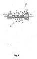
- the transmission mechanism 28, as can be seen in fig. 4 comprises an intermediate shaft 29 connected with the first end 30 to the free end 31 of the main shaft 27 through a first Hooke's joint 32 and connected with the second end 33 to the shaft 21 of the cable-winding bush 19 through a second Hooke's joint 90.
- the first Hooke's joint 32 consists, in a per se known way, of a four point cross 39 connected by means of four links to a driving fork and to a driven fork made, respectively, at the free end 31 of the main shaft 27 and at the first end 30 of the intermediate shaft 29.
- the second Hooke's joint 90 consists, in a per se known way, of a four point cross 91 connected by means of four links to the second end 33 of the intermediate shaft 29 and to the free end of the shaft 21 of the cable-winding bush 19.
- a sliding connection 80 is defined between the intermediate shaft 29 and the shaft 21 of the cable-winding bush 19 .
- Such a sliding connection 80 comprises two slots 34, 35, made on the portion of the intermediate shaft 29 facing towards its second end 33, which slidably receive two projecting ends 36, 37 of the four point cross 91.
- the sliding connection 80 allows the axial sliding of the intermediate shaft 29 with respect to the shaft 21 of the cable-winding bush 19, as can be seen in the two different operative conditions of figs. 2 and 3 .
- the transmission mechanism 28 therefore consists of a double Hooke's joint with intermediate shaft and a sliding connection that allow both the transmission of the rotation motion between the main shaft 27 and the shaft 21 of the cable-winding bush 19, a situation that occurs during gearshifting, and the positioning of the same shafts on directions inclined with respect to each other, a situation that occurs during braking ( fig. 3 ).
- the sliding connection could be made in a different way, for example by providing two slots made on the portion of intermediate shaft 29 facing towards its first end 30 that slidably receive the projecting ends of the four point cross of the first Hooke's joint 32 or else by providing, instead of the slots 34, 35, the division of one or more of the main shaft 27, the intermediate shaft 29 and the shaft 21 of the cable-winding bush 19 into two telescopic half-shafts that rotate as a unit.
- the control group 8, described with particular reference to figures 5 to 16 comprises, as stated above, the lever 9, the indexing mechanism 12 and the intermediate body 11, in turn formed from the plate 13.
- a cover 18 is associated at the front with the lever 9 to cover the indexing mechanism 12.
- the indexing mechanism 12 makes the main shaft 27 take up a series of predetermined angular positions about the axis X2, which is substantially parallel to the direction X of movement of the bicycle.
- the indexing mechanism 12 makes the main shaft 27 rotate in a first direction as a consequence of a rotation of the lever 9 by a comparatively small angle in a first direction, indicated with S, and makes the main shaft 27 rotate in the opposite direction as a consequence of a rotation of the lever of the gearshift 9 by a comparatively large angle in the same direction S.
- the indexing mechanism 12 comprises a gear wheel 45, which rotates as a unit with the aforementioned main shaft 27 and is rotatable with respect to the intermediate body 11 about the second rotation axis X2.
- the axis X2 is aligned with the rotation axis X3 of the shaft 21 of the cable-winding bush 19.
- the gear wheel 45 therefore, is biased into rotation in the direction of unwinding U of the traction cable 20 of the derailleur, by the traction that acts upon the cable-winding bush 19.
- a connecting rod 46 is mounted so that it can rotate around the main shaft 27 and is provided with a shank 42 carried by the support plate 13 in a hole 13 so that it can rotate.
- a locknut 43 is screwed on the outside of the shank 42 to avoid the connecting rod 46 slipping away from the support plate 13.
- the connecting rod 46 is forced in the direction of unwinding U against the support plate 13 by return means, for example by a compression coil spring 47, extending between the support plate 13 and an appendix 46a of the connecting rod 46.
- the compression coil spring 47 could be replaced by a spiral spring having one end connected in a point of the connecting rod 46 and the other end connected to the support plate 13, in which case the connecting rod 46 could be without the appendix 46a.
- the lever 9, only partially visible in figures 5 to 16 is hinged to the connecting rod 46 through a pivot 48 extending along a rotation axis X4.
- Return means, for example in the form of a spiral spring 49 schematically illustrated in figures 5 to 16 bias the lever 9 into a predetermined angular position with respect to the connecting rod 46 (substantially vertical in figure 5 ), counteracting the vibrations caused in riding the bicycle.
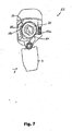
- a first ratchet 50 is made at the end of the driven arm 9b of the lever 9 to cooperate with a plurality of first teeth 51 of a first toothed sector 45a of the gear wheel 45. More specifically, the first teeth 51, seen in direction U, have a side with comparatively low inclination with respect to the tangent to the gear wheel 45, and a side with comparatively high inclination with respect to the tangent to the gear wheel 45.
- the first ratchet 50 has a shape matching the shape of a space 52 between two adjacent teeth 51 and therefore has a side suitable for abutting pushing on the side with comparatively high inclination of the first teeth 51, therefore called "active side" of the teeth.
- the first ratchet 50 also has a side suitable for sliding on the side with comparatively low inclination of the first teeth 51, therefore called “inactive side” of the teeth. In the rest condition of the indexing mechanism 12 shown in figure 5 , the first ratchet 50 is in a position out of engagement with the first teeth 51.
- a second ratchet 53 is made at the end of a driven arm 54a of a rocker arm 54 that is hinged to the support plate 13 through a pivot 55.
- the second ratchet 53 cooperates with a plurality of second teeth 56 of a second toothed sector 45b of the gear wheel 45.
- the second teeth 56 seen in direction U, also have a side with comparatively low inclination with respect to the tangent to the gear wheel 45 and a side with comparatively high inclination with respect to the tangent to the gear wheel 45.
- the second ratchet 53 has a shape matching the shape of a space 57 between two adjacent teeth 56 and therefore has a side suitable for acting as abutment against the side with comparatively high inclination of the second teeth 56, therefore called “active side” of the teeth.
- the second ratchet 53 also has a side suitable for sliding on the side with comparatively low inclination of the second teeth 56, therefore called “inactive side” of the teeth.
- the ratchets 50 and 53 have a shape matching the respective spaces 52 and 57; for the purposes of the invention, however, it is sufficient that the shape of the ratchets 52 and 57 be compatible with that of the respective spaces 52 and 57, i.e. that it can allow the pushing engagement on the active side and on the other hand can slide without becoming blocked on the inactive side.
- the teeth 51 and 56 for engagement with the two ratchets 50, 53 can be different to each other, but preferably they are the same in number and geometry, so that the gear wheel can be mounted indifferently in two positions angularly spaced by 180°.
- the gear wheel 45 (and therefore the cable-winding bush 19) is kept in a predetermined angular position by the engagement of the second ratchet 53 in the space indicated with 57a, an engagement that counteracts the traction force in the direction of unwinding U, due to the cable 20.
- the lever 9 is also in rest position, substantially vertical as illustrated.
- the first ratchet 50 made on the driven arm 9b of the lever 9 and therefore in rotation about the pivot 48, faces one of the spaces, indicated with 52a, between the first teeth 51, without its side going, however, straight into contact with the active side of the tooth indicated with 51a.
- the driving arm 54b of the rocker arm 54 is biased to slide on the driven arm 9b of the lever 9 and therefore the rocker arm 54 oscillates in the direction indicated with the arrow 59, against the force of the compression spring 58, i.e. compressing it.
- the second ratchet 53 therefore disengages from the space 57a in which it was engaged.
- the gear wheel 45 (and the cable-winding bush 19) are therefore free to carry out a small rotation as a unit in the direction of unwinding U of the traction cable.
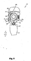
- the condition represented in figure 6 is therefore a non-static condition, and the indexing mechanism 12 goes substantially immediately into the condition represented in figure 7 , in which the active side of the tooth 51a abutted on the first ratchet 50.
- the lever 9 is released in this operative condition, it is pulled back by the spiral spring 49 in the direction S' indicated in figure 8 , opposite the direction S, and determines the sliding of the first ratchet 50 out from the space 52a, as shown in figure 8 .
- the pushing action by the driven arm 9b of the lever 9 on the driving arm 54b of the rocker arm 54 also ceases.
- the rocker arm 54 is therefore biased, by the action of the spring 58, in the direction 60 of rotation about its pivot 55, opposite the aforementioned direction 59.
- the second ratchet 53 therefore reaches an abutting relationship on the inactive side of the tooth 56a, at the side of the space 57b.
- the driving arm 54b of the rocker arm 54 may or may not lose the abutting relationship on the driven arm 9b of the lever, according to the release speed of the lever 9 by the cyclist.
- the gear wheel 45 (and therefore the cable-winding bush 19) carry out an angular rotation in the direction of unwinding U of the brake cable, of an angular extent corresponding to the pitch between the second teeth 56.
- Such a rotation corresponds to the release of a length of the traction cable 20 such as to move the derailleur and therefore the transmission chain at the adjacent gear wheel of the sprocket set - or of the crankset respectively.
- a release movement is in the direction of a gear wheel of smaller diameter, or downward gearshifting. In other types of gearshift, however, the release movement can determine gearshifting towards a gear wheel of greater diameter, or upward gearshifting.
- the lever 9 is pushed by the cyclist in the same direction S illustrated in figure 6 , but making it rotate further.
- the initial operation of the indexing mechanism 12 is the same as that described above with reference to figures 5 to 7 .
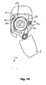
- the second ratchet 53 slides on the inactive side of the tooth indicated with 56c, the next one in the direction of winding W, as illustrated in figure 12 ; it passes over its crest, as illustrated in figure 13 ; and it engages in the space indicated with 57c, the next one in the direction of winding W, as illustrated in figure 14 .
- the gear wheel 45 and therefore the cable-winding bush 19 carry out an angular rotation in the direction of winding W of the traction cable 20, of angular extent corresponding to the pitch between the second teeth 56.
- Such a rotation corresponds to the winding of a length of the traction cable 20 such as to move the derailleur and therefore the transmission chain at the adjacent gear wheel of the sprocket set - or of the crankset respectively.
- a winding movement is in the direction of a gear wheel of greater diameter, or upward gearshifting. In other types of gearshift, however, the winding movement can determine gearshifting towards a gear wheel of smaller diameter, or downward gearshifting,
- a control device 100 which differs from the control device 1 of the mechanical type, described with reference to figures 1 to 16 , in that the control device 100 is suitable for being used in a bicycle equipped with a servo-assisted gearshifting system, of the electric/electronic or hydraulic type.
- the control device 100 does not therefore act in traction or in release on a derailleur control cable, but through the actuation of the command lever 109 the control device 100 supplies electrical signals in output that are suitably processed by an electronic unit of the system, which then commands the deraille through electric actuators.
- the two functions could be inverted, making a first movement with an angular excursion of comparatively low extent on the lever 109 in direction S correspond to upward gearshifting and a movement with an angular excursion of comparatively high extent on the lever 109, again in the same direction S, correspond to downward gearshifting.
- the control device 100 comprises a support body 104 with a side 105 for connection to the handlebars 2 and a portion 107, projecting from the side 105, that can be gripped by the cyclist during travel.
- a control group 108 comprising an actuator group 112 and a lever 109, cooperating with the actuator group 112, is mounted on the support body 104.
- the support body 104 also comprises an intermediate body 111 hinged to the support body 104 in a pivot 114 arranged along a first rotation axis X1, substantially horizontal and perpendicular to the direction of movement X of the bicycle.
- the lever 109 able to rotate about a second axis X2, and the actuator group 112 are mounted on the intermediate body 111.
- the intermediate body 111 is formed from a plate 113 hinged to the support body 104 in the aforementioned pivot 114.
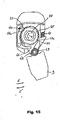
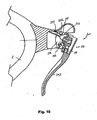
- the intermediate body 111 rotates about the pivot 114, as can be seen in fig. 18 , taking the control group 108 into rotation and pulling the widened head 116a of the brake cable 116 to carry out braking.
- the control group 108 comprises, as stated above, the lever 109, the actuator group 112 and the intermediate body 111, in turn formed from the plate 113.
- a cover 118 is associated at the front with the lever 109 to cover the actuator group 112.
- the actuator group 112 comprises a connecting rod 146 mounted so that it can rotate about the second rotation axis X2 and provided with a first shank 142 carried by the support plate 113 in a hole 113a so that it can rotate.
- a locknut 143 is screwed on the outside of the shank 142 to avoid the connecting rod 146 slipping away from the support plate 113.
- the connecting rod 146 has an inner cylindrical cavity 148.
- the connecting rod 146 is forced in direction U against the support plate 113 by return means, for example by a compression spring 147, extending between the support plate 113 and an appendix 146a of the connecting rod 146.
- the compression coil spring 147 could be replaced by a spiral spring having one end connected in a point of the connecting rod 146 and the other end connected to the support plate 113, in which case the connecting rod 146 could be without the appendix 146a.
- the connecting rod 146 is provided with a second shank 146c having on its outer surface a first switch 151 and an actuation tooth 146d, visible in figures 19 , 20 and 21 .
- the first switch 151 is electrically connected to a cable 152 arranged passing inside the cylindrical cavity 148 and extends towards the handlebars to reach an electronic unit of the bicycle (not shown).
- a second switch 153 is associated with the support plate 113.
- the second switch 153 is electrically connected to a cable 154 that extends towards the handlebars to also reach the electronic unit of the bicycle.
- the lever 109 is hinged to the connecting rod 146 through a pivot 148 arranged according to the axis X3.
- Return means for example in the form of a spiral spring 149, bias the lever 109 into a predetermined angular position with respect to the connecting rod 146 (substantially vertical in figure 19 ), counteracting the vibrations caused when riding the bicycle.
- An actuation tooth 150 is made at the end of the driven arm 109b of the lever 109 to cooperate with the first switch 151 of the connecting rod 146. In the rest condition of the actuator group 112 shown in figure 19 , the actuation tooth 150 is in a position not in contact with the switch 151.
- the actuation tooth 150 made on the driven arm 109b of the lever 109 is therefore taken into rotation about the pivot 148 until it makes contact with the switch 151 and it is actuated ( fig. 20 ).
- the electronic unit detects the actuation of such a switch 151 through the signal carried through the cable 152.
- another type of transmission could be provided for such a signal, for example a radio frequency wire-less transmission, therefore eliminating the cable 152.
- the electronic unit has detected the first signal at the moment in time T1.
- the lever 109 is pushed by the cyclist in the same direction S, but making it rotate further.
- the initial operation of the actuator group 112 is the same as that described above with reference to figures 19 and 20 with the actuation of the switch 151 at the moment in time T1.
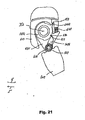
- the actuation tooth 150 acts by pushing on the switch 151 and on the connecting rod 146. More specifically, the lever 109 now rotates as a unit with the connecting rod 146 about the second axis X2, against the action of the compression spring 147.
- the actuation tooth 146d is taken into contact with the switch 153 ( fig. 21 ).
- the electronic unit detects the actuation of such a switch 153 through the signal carried through the cable 154.
- another type of transmission could be provided for such a signal, for example a wire-less radio frequency transmission, therefore eliminating the cable 154.
- the connecting rod 146 and the lever 109 finally go back into the respective rest positions under the action of the springs 147 and 149, respectively, and the actuation tooth 150 also disengages from the first switch 151.
- Downward and upward gearshifting is achieved by the electronic unit of the system through processing of said two signals detected at moments in time T1 and T2.
- a method for managing the two signals coming from 151 and 153 can be the following.
- the electronic unit waits for the lever 109 to be released, which can be detected at the moment when the two switches 151 and 153 are no longer actuated. In this way, every angular excursion of the lever 109, small or large, corresponds to single gearshifting (downwards or upwards).
- the logic control unit carries out multiple gearshifting until the lever 109 is released.
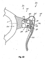
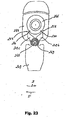
- a control device 200 is shown, which - like the control device 100 -is suitable for being used in a bicycle equipped with a servo-assisted gearshifting system.
- the control device 200 comprises a support body 204 with a side 205 for connection to the handlebars 2 and a portion 207, projecting from the side 205, that can be gripping by the cyclist when riding.
- a control group 208 comprising an actuator group 212 and a lever 209, cooperating with the actuator group 212, is mounted on the support body 204.
- the support body 204 also comprises an intermediate body 211 hinged to the support body 204 in a pivot 214 arranged along a first rotation axis X1, substantially horizontal and perpendicular to the direction of movement X of the bicycle.
- the lever 209 able to rotate about a second axis X3 is mounted on the intermediate body 211.
- the intermediate body 211 is formed from a plate 213 hinged to the support body 204 in the aforementioned pivot 214.
- the control group 208 comprises, as stated above, the lever 209, the actuator group 212 and the intermediate body 211, in turn formed from the plate 213.
- a cover 218 is associated at the front with the lever 209 to cover the actuator group 212.
- the support plate 213 is provided with a shank 246 having on its outer surface a first switch 251 and a second switch 253.
- the first switch 251 is electrically connected to a cable 252 arranged passing inside the cylindrical cavity 248 of the support plate 213 and extends towards the handlebars to reach an electronic unit of the bicycle (not shown).
- the second switch 253 is electrically connected to a cable 254 arranged passing inside the cylindrical cavity 248 and extends towards the handlebars to also reach the electronic unit of the bicycle.
- the lever 209 is hinged to the support plate 213 through a pivot 248 arranged according to the axis X3.
- Return means for example in the form of one or more spiral springs 249, bias the lever 209 into a predetermined angular position with respect to the support body 213 (substantially vertical in figure 23 ), counteracting the vibrations caused in riding the bicycle.
- a first actuation tooth 250 is made at the end of a first driven arm 209b of the lever 209 to cooperate with the first switch 251.
- a second actuation tooth 260 is made at the end of a second driven arm 209c of the lever 209 to cooperate with the second switch 253.
- the electronic unit detects the actuation of such a switch 251 through the signal carried through the cable 252.
- the electronic unit detects the actuation of such a second switch 253 through the signal carried through the cable 254.
- Downward and upward gearshifting is achieved by the electronic unit of the system through processing of said two signals detected by the actuation of the two switches 251 and 253.
Landscapes
- Engineering & Computer Science (AREA)
- Mechanical Engineering (AREA)
- Chemical & Material Sciences (AREA)
- Combustion & Propulsion (AREA)
- Transportation (AREA)
- Steering Devices For Bicycles And Motorcycles (AREA)
- Mechanical Control Devices (AREA)
- Control Of Vehicle Engines Or Engines For Specific Uses (AREA)
Claims (32)
- Dispositif de contrôle intégré pour une bicyclette, comprenant un corps de support (4, 104) approprié pour être fixé sur le guidon (2) d'une bicyclette et un levier simple (9, 109) qui est mobile par rapport au corps de support (4, 104) pour commander à la fois un frein et un dérailleur dans deux première et deuxième directions de mouvement, opposées l'une par rapport à l'autre, dans lequel le levier simple (9, 109) a une position de repos dans laquelle il ne commande ni le frein ni le dérailleur et il est mobile dans une première direction (X) pour commander le frein,caractérisé en ce quele levier simple (9, 109) est mobile dans une deuxième direction (S) qui est différente de la première directiond'une première amplitude pour le mouvement du dérailleur dans sa première direction, etd'une deuxième amplitude différente de la première amplitude pour le mouvement du dérailleur dans sa deuxième direction,le dispositif comprenant un corps intermédiaire (11, 111), qui est supporté de sorte qu'il puisse se déplacer en rotation par rapport au corps de support (4, 104) autour d'un premier axe de rotation (X1), ledit levier simple (9, 109) pouvant se déplacer en rotation par rapport au corps intermédiaire (11, 111) autour d'un deuxième axe de rotation (X2), différent du premier.
- Dispositif selon la revendication 1, dans lequel la deuxième direction (S) est sensiblement perpendiculaire à la première direction (X).
- Dispositif selon la revendication 1, dans lequel le mouvement du dérailleur dans la première direction correspond à un changement de vitesse vers le bas et le mouvement du dérailleur dans la direction opposée correspond à un changement de vitesse vers le haut.
- Dispositif selon la revendication 1, dans lequel le mouvement du dérailleur dans la première direction correspond à un changement de vitesse vers le haut et le mouvement du dérailleur dans la direction opposée correspond à un changement de vitesse vers le bas.
- Dispositif selon la revendication 1, dans lequel le corps de support (4, 104) peut être saisi dans une main.
- Dispositif selon la revendication 1, dans lequel, lorsque le levier simple (9) est dans la position de repos, ledit deuxième axe de rotation (X2) pointe sensiblement dans la direction (X) du mouvement de la bicyclette et ledit premier axe de rotation (X1) pointe sensiblement dans une direction transversale par rapport à la direction (X) de mouvement de la bicyclette.
- Dispositif selon la revendication 6, dans lequel ledit premier axe de rotation (X1) est sensiblement horizontal.
- Dispositif selon la revendication 6, dans lequel ledit premier axe de rotation est sensiblement vertical.
- Dispositif selon la revendication 1, dans lequel le corps intermédiaire (11, 111) comprend un logement (15, 115) destiné à recevoir une tête élargie (16a, 116a) d'un câble de contrôle de frein (16, 116), dans une position éloignée par rapport audit premier axe de rotation (X1).
- Dispositif selon la revendication 1, comprenant une tige de connexion (46, 146) montée de sorte qu'elle puisse se déplacer en rotation par rapport au corps intermédiaire (11, 111) autour du deuxième axe de rotation (X2), dans lequel le levier simple mobile (9, 109) est articulé sur la tige de connexion (46, 146) selon un troisième axe de rotation (X3), différent du deuxième axe de rotation (X2) et parallèle à celui-ci, dans lequel le levier simple (9, 109) est mobile de manière angulaire par rapport à la tige de connexion (46, 146) autour du troisième axe de rotation (X3) entre une position de repos et une position déviée, et dans lequel la tige de connexion (46, 146) est mobile de manière angulaire par rapport au corps intermédiaire (11, 111) autour du deuxième axe de rotation (X2) entre une position de repos et au moins une position déviée.
- Dispositif selon la revendication 10, comprenant un premier élément élastique (47, 147) entre la tige de connexion (46, 146) et le corps intermédiaire (11, 111) pour pousser la tige de connexion (46, 146) vers sa position de repos et un deuxième élément élastique (49, 149) entre le levier simple (9, 109) et la tige de connexion (46, 146) pour pousser le levier simple (9, 109) vers sa position de repos.
- Dispositif selon la revendication 11, dans lequel le premier élément élastique (47, 147) exerce une poussée sur la tige de connexion (9, 109) qui prévaut par rapport au deuxième élément élastique (49, 149), de sorte qu'une poussée sur le levier simple (9, 109) détermine tout d'abord le mouvement du levier simple (9, 109) dans la position déviée sans mouvement de la tige de connexion (46, 146) puis un mouvement de la tige de connexion (46, 146).
- Dispositif selon l'une quelconque des revendications 10 à 12, approprié pour commander un dérailleur actionné par un câble de contrôle (20), le dispositif comprenant :- une douille d'enroulement de câble (19), supportée de sorte qu'elle puisse se déplacer en rotation sur le corps de support (4), sur laquelle douille (19) le câble de contrôle de dérailleur (20) est enroulé,- un mécanisme d'indexation (12) qui comprend une roue dentée (45) supportée de sorte qu'elle puisse se déplacer en rotation sur le corps intermédiaire (11) autour du deuxième axe de rotation entre un nombre prédéterminé de positions angulaires prédéterminées correspondant aux positions souhaitées du dérailleur,- un mécanisme de transmission (28) entre la douille d'enroulement de câble (19) et la roue dentée (45) du mécanisme d'indexation (12), de sorte qu'une rotation de la roue dentée (45) corresponde à une rotation de la douille d'enroulement de câble (19).
- Dispositif selon la revendication 13, dans lequel le mécanisme de transmission (28) comprend une connexion coulissante (80) appropriée pour permettre le mouvement dudit mécanisme d'indexation (12) par rapport à ladite douille d'enroulement de câble (19).
- Dispositif selon la revendication 14, dans lequel le mécanisme de transmission (28) permet une rotation dudit corps intermédiaire (11) autour dudit premier axe de rotation (X1).
- Dispositif selon la revendication 15, dans lequel ladite connexion coulissante (80) comprend au moins une fente (34, 35) qui reçoit avec possibilité de coulissement un élément protubérant (36, 37) associé à ladite douille d'enroulement de câble (19) et/ou à ladite roue dentée (45).
- Dispositif selon la revendication 15, dans lequel ledit mécanisme de transmission (28) comprend un arbre intermédiaire (29), un premier joint de cardan (32) et un deuxième joint de cardan (90), ledit premier joint de cardan (32) connectant ledit arbre intermédiaire (29) à ladite roue dentée (45) dudit mécanisme d'indexation (12) et ledit deuxième joint de cardan (90) connectant ledit arbre intermédiaire (29) à ladite douille d'enroulement de câble (19).
- Dispositif selon la revendication 13, dans lequel :- la roue dentée (45) comprend des premier et deuxième secteurs (45a, 45b), dans chacun desquels des première et deuxième dents (51, 56) sont formées qui définissent entre elles un nombre d'espaces (52, 57) au moins un égal audit nombre prédéterminé de positions angulaires,- le levier simple (9) comprend un bras entraîné (9b) orienté vers le premier secteur (45a), doté d'un premier cliquet (50) d'une forme compatible avec la forme d'un espace (51) du premier secteur (45a),le dispositif comprenant également :- un bras oscillant (54), articulé sur le corps intermédiaire (11) selon un quatrième axe de rotation parallèle aux deuxième et troisième axes de rotation (X2, X3) et doté d'un premier bras (54b) orienté vers le bras entraîné (9b) du levier simple (9) et d'un deuxième bras (54a) orienté vers le deuxième secteur (45b) et équipé d'un deuxième cliquet (53) d'une forme compatible avec la forme d'un espace (57) du deuxième secteur (45b), et- un troisième élément élastique (58) entre le corps intermédiaire (11) et le bras oscillant (54) pour pousser le bras oscillant (54) avec son deuxième bras (54a) en direction du deuxième secteur (45b),et dans lequel :- le bras entraîné (9b) du levier simple (9) pousse sur le premier bras (54b) du bras oscillant (54) à la différence du troisième élément élastique (58) lorsque le levier simple (9) est déplacé de sa position de repos vers sa position déviée.
- Dispositif selon la revendication 18, dans lequel les espaces (52, 57) des premier et deuxième secteurs (45a, 45b) sont définis par un côté actif et par un côté inactif, le côté actif étant orienté, par rapport à l'espace (52, 57), suivant une première direction de rotation de la roue dentée (45) correspondant à une rotation de la douille d'enroulement de câble (19) dans la direction d'enroulement du câble de contrôle de dérailleur (20).
- Dispositif selon la revendication 19, dans lequel, lorsque le levier (9) et la tige de connexion (46) sont dans leurs positions de repos, le premier cliquet (50) n'est engagé avec aucun espace (52) du premier secteur (45a) alors que le deuxième cliquet (53) est engagé dans l'un des espaces (57) du deuxième secteur (45b), le deuxième cliquet (53) étant en butée contre le côté actif de l'espace (57), de manière à empêcher une rotation de la roue dentée (45) dans une deuxième direction de rotation opposée à la première direction de rotation.
- Dispositif selon la revendication 20, dans lequel, lorsque le levier (9) est amené de sa position de repos à sa position déviée sans que la tige de connexion (46) ne soit déplacée de sa position de repos, le premier cliquet (50) est pris en engagement partiel dans l'un des espaces (52) du premier secteur (45a), à une certaine distance du côté actif, alors que le deuxième cliquet (53) est sorti de l'engagement avec l'espace (57) du deuxième secteur (45b), opposé audit espace (57), de sorte que la roue dentée (45) puisse tourner dans la deuxième direction de rotation en raison de la traction du câble de contrôle de dérailleur (20) d'une petite amplitude, suffisante pour que le premier cliquet (50) se déplace contre le côté actif de l'espace (52) dans lequel il est engagé alors que le deuxième cliquet (53) passe de la position opposée à l'espace (57) dans lequel il était engagé à une position opposée à l'espace adjacent (57).
- Dispositif selon la revendication 21, dans lequel, lorsque le levier (9) est ramené à sa position de repos à partir de sa position déviée, sans que la tige de connexion (46) ne soit déplacée de sa position de repos, le deuxième cliquet (53) vient en engagement avec l'espace (57) auquel il était opposé, alors que le premier cliquet (50) est sorti de l'engagement avec l'espace (52) dans lequel il était engagé.
- Dispositif selon la revendication 21, dans lequel, lorsque la tige de connexion (46) est sortie de sa position de repos vers sa position déviée, avec le levier (9) qui reste dans sa position déviée par rapport à la tige de connexion (46), le premier cliquet (50) reste engagé dans l'espace (52) et pousse le côté actif de l'espace (52), ce qui amène la roue dentée (45) à tourner dans la première direction, alors que le deuxième cliquet (53) est pressé par le troisième élément élastique (58) contre la roue dentée (45) et coulisse sur le côté inactif des espaces (57) sans s'opposer à la rotation de la roue dentée (45).
- Dispositif selon la revendication 23, dans lequel, lorsque la tige de connexion (46) et le levier (9) sont ramenés dans leurs positions de repos, le premier cliquet (50) est sorti de l'engagement avec la roue dentée (45) alors que le deuxième cliquet (53) reste engagé dans l'un des espaces (57), en empêchant la rotation de la roue dentée (45) dans la deuxième direction.
- Dispositif selon l'une quelconque des revendications 10 à 12, approprié pour commander un dérailleur actionné par un système assisté, comprenant un premier détecteur de mouvement (151) entre ledit levier simple (109) et ladite tige de connexion (146) et un deuxième détecteur de mouvement (153) entre ladite tige de connexion (146) et ledit corps intermédiaire (111).
- Dispositif selon la revendication 25, dans lequel le premier détecteur de mouvement est un premier détecteur de contact (151) actionné par un contact entre la tige de connexion (146) et un bras entraîné (109b) du levier simple (109) lorsqu'il atteint sa position déviée, et dans lequel le deuxième détecteur de mouvement est un deuxième détecteur de contact (153) actionné par un contact entre une protubérance (146d) de la tige de connexion (146) et ledit corps intermédiaire (111) lorsque la tige de connexion (146) atteint sa position déviée.
- Dispositif selon la revendication 26, dans lequel le premier détecteur de contact (151) est prévu dans un logement sur la tige de connexion (146).
- Dispositif selon la revendication 25, dans lequel le deuxième détecteur de contact (153) est prévu dans un logement sur le corps intermédiaire (111).
- Dispositif selon la revendication 25, dans lequel ledit système assisté comprend un moteur électrique.
- Procédé pour contrôler un dispositif intégré de bicyclette selon la revendication 1 comprenant un système de freinage et au moins un dispositif de changement de vitesse avec un dérailleur qui est mobile dans deux première et deuxième directions opposées de mouvement, comprenant :- l'actionnement d'un levier (9, 109, 209) dans une première direction (X) pour commander le système de freinage pour obtenir un freinage,- l'actionnement du même levier (9, 109, 209) dans une deuxième direction (S) qui est différente de la première direction (X) pour commander le mouvement du dérailleur dans sa première direction,- l'actionnement du même levier (9, 109, 209) dans une troisième direction (S, S') différente de la première direction (X) pour commander le mouvement du dérailleur dans sa deuxième direction,caractérisé en ce que- la troisième direction (S) est identique à la deuxième direction (S), et- l'actionnement du levier (9, 109) dans la deuxième direction (S) pour commander le mouvement du dérailleur dans sa première direction a une amplitude différente par comparaison à l'actionnement du même levier (9, 109) dans la même direction (S) pour commander le mouvement du dérailleur dans sa deuxième direction.
- Procédé selon la revendication 30, dans lequel la première direction (X) de mouvement du levier (9, 109, 209) est sensiblement perpendiculaire aux deuxième (S) et troisième (S, S') directions de mouvement du levier (9, 109, 209).
- Procédé selon la revendication 30, dans lequel l'actionnement du levier (9, 109, 209) dans la première direction (X) se produit en même temps que l'actionnement du levier (9, 109, 209) dans les deuxième (S) et/ou troisième (S, S') directions.
Applications Claiming Priority (1)
| Application Number | Priority Date | Filing Date | Title |
|---|---|---|---|
| IT000239A ITMI20070239A1 (it) | 2007-02-09 | 2007-02-09 | Dispositivo di comando per un deragliatore di bicicletta |
Publications (4)
| Publication Number | Publication Date |
|---|---|
| EP1955937A2 EP1955937A2 (fr) | 2008-08-13 |
| EP1955937A3 EP1955937A3 (fr) | 2012-09-26 |
| EP1955937B1 EP1955937B1 (fr) | 2014-01-22 |
| EP1955937B2 true EP1955937B2 (fr) | 2018-04-04 |
Family
ID=38596570
Family Applications (1)
| Application Number | Title | Priority Date | Filing Date |
|---|---|---|---|
| EP08002171.0A Active EP1955937B2 (fr) | 2007-02-09 | 2008-02-06 | Dispositif de contrôle du dérailleur d'une bicyclette |
Country Status (7)
| Country | Link |
|---|---|
| US (1) | US9045193B2 (fr) |
| EP (1) | EP1955937B2 (fr) |
| JP (1) | JP2008195385A (fr) |
| CN (1) | CN101239647A (fr) |
| IT (1) | ITMI20070239A1 (fr) |
| RU (1) | RU2008104868A (fr) |
| TW (1) | TW200911612A (fr) |
Families Citing this family (44)
| Publication number | Priority date | Publication date | Assignee | Title |
|---|---|---|---|---|
| ITTO20011079A1 (it) | 2001-11-16 | 2003-05-16 | Campagnolo Srl | ,,dispositivo di comando del cambio per una bicicletta avente un manubrio con estremita' diritte,, |
| EP1564131B1 (fr) * | 2004-02-06 | 2007-08-15 | Campagnolo S.R.L. | Dispositif d'actionnement pour un câble de commande de changement de vitesse pour bicyclette |
| US7779718B2 (en) * | 2005-03-03 | 2010-08-24 | Sram, Llc | Bicycle shifter |
| EP2042420B1 (fr) | 2005-06-27 | 2011-08-17 | CAMPAGNOLO S.r.l. | Dispositif de commande pour dérailleur de bicyclette |
| JP5027999B2 (ja) * | 2005-07-08 | 2012-09-19 | キヤノン株式会社 | 記録装置およびその制御方法 |
| DE602006016343D1 (de) * | 2006-01-23 | 2010-09-30 | Campagnolo Srl | Steuervorrichtung für fahrradkettenschaltung |
| EP1826111B1 (fr) | 2006-02-23 | 2010-06-30 | CAMPAGNOLO S.r.l. | Appareil de contrôle de frein de bicyclette |
| ITMI20070239A1 (it) | 2007-02-09 | 2008-08-10 | Campagnolo Srl | Dispositivo di comando per un deragliatore di bicicletta |
| ITMI20070400A1 (it) | 2007-03-01 | 2008-09-02 | Campagnolo Srl | Dispositivo di comando per bicicletta e bicicletta comprendente tale dipsositivo |
| ITMI20072230A1 (it) * | 2007-11-23 | 2009-05-24 | Campagnolo Srl | Dispositivo di comando per bicicletta con manubrio ricurvo |
| EP2065298B1 (fr) | 2007-11-29 | 2011-09-28 | Shimano Inc. | Dispositif de commande d'une bicyclette |
| JP2009149210A (ja) | 2007-12-20 | 2009-07-09 | Shimano Inc | 自転車用操作装置 |
| US8863611B2 (en) | 2008-10-08 | 2014-10-21 | Sram, Llc | Bicycle control device |
| JP2011159111A (ja) * | 2010-02-01 | 2011-08-18 | Shimano Inc | 自転車用ブレーキ及び変速操作装置 |
| US8869648B2 (en) * | 2010-06-28 | 2014-10-28 | Shimano Inc. | Bicycle brake and shift operating device |
| US9365258B2 (en) | 2010-06-28 | 2016-06-14 | Shimano Inc. | Bicycle brake and shift operating device |
| EP2399814B1 (fr) * | 2010-06-28 | 2015-06-10 | Shimano, Inc. | Dispositif d'actionnements de levier de vitesse et de frein pour bicyclette |
| EP2468614B1 (fr) * | 2010-12-03 | 2013-10-02 | Campagnolo S.r.l. | Dispositif d'actionnement pour câble de contrôle d'un changement de vitesses de bicyclette |
| US9327792B2 (en) | 2011-01-28 | 2016-05-03 | Paha Designs, Llc | Gear transmission and derailleur system |
| US9033833B2 (en) | 2011-01-28 | 2015-05-19 | Paha Designs, Llc | Gear transmission and derailleur system |
| US10207772B2 (en) | 2011-01-28 | 2019-02-19 | Paha Designs, Llc | Gear transmission and derailleur system |
| US8752450B2 (en) | 2011-06-14 | 2014-06-17 | Shimano Inc. | Bicycle component operating device |
| US10239581B2 (en) | 2011-08-26 | 2019-03-26 | Gevenalle, Inc | Bicycle brake and shift lever assembly |
| WO2013117450A1 (fr) * | 2012-02-06 | 2013-08-15 | Rotor Componentes Tecnológicos S.L | Dispositif de changement de vitesse à simple effet de bicyclette et son mécanisme de fonctionnement du type unidirectionnel |
| US10730580B2 (en) | 2014-01-21 | 2020-08-04 | Shimano Inc. | Bicycle control device |
| US9919760B2 (en) * | 2014-03-12 | 2018-03-20 | Shimano Inc. | Bicycle operating device |
| US10550858B2 (en) | 2014-08-25 | 2020-02-04 | Shimano Inc. | Bicycle control device |
| JP5937649B2 (ja) * | 2014-09-05 | 2016-06-22 | 株式会社シマノ | 自転車用シフターおよびこれを備える自転車用電動システム |
| US9321501B1 (en) | 2014-10-31 | 2016-04-26 | Shimano Inc. | Bicycle control device |
| US10933949B2 (en) * | 2014-11-27 | 2021-03-02 | Shimano Inc. | Bicycle operating apparatus and bicycle operating system |
| USD774429S1 (en) * | 2015-12-03 | 2016-12-20 | Helio Ascari | Bicycle brake lever |
| US11027709B2 (en) | 2016-04-21 | 2021-06-08 | Shimano Inc. | Bicycle operating device |
| US10486658B2 (en) * | 2016-04-21 | 2019-11-26 | Shimano Inc. | Bicycle operating device |
| US10843763B2 (en) | 2016-04-21 | 2020-11-24 | Shimano Inc. | Bicycle operating device |
| US10407121B2 (en) | 2016-04-21 | 2019-09-10 | Shimano Inc. | Bicycle operating device |
| US10604206B2 (en) | 2016-04-21 | 2020-03-31 | Shimano Inc. | Bicycle operating device |
| US10759489B2 (en) | 2016-04-21 | 2020-09-01 | Shimano Inc. | Bicycle operating device |
| US10858063B2 (en) | 2016-04-21 | 2020-12-08 | Shimano Inc. | Bicycle operating device |
| US10414463B2 (en) | 2016-08-26 | 2019-09-17 | Shimano Inc. | Bicycle operating device |
| CN106892051B (zh) * | 2017-03-16 | 2022-05-17 | 珠海蓝图控制器科技有限公司 | 一种自行车换挡器 |
| JP6921724B2 (ja) * | 2017-11-30 | 2021-08-18 | 株式会社シマノ | 変速制御装置および電動変速システム |
| USD951752S1 (en) * | 2019-07-29 | 2022-05-17 | Craig Heisner | Simulated brake hood for a bicycle |
| TWI763544B (zh) * | 2021-06-18 | 2022-05-01 | 財團法人工業技術研究院 | 致動器 |
| TWM624724U (zh) | 2021-10-15 | 2022-03-21 | 巨大機械工業股份有限公司 | 自行車控制裝置 |
Citations (10)
| Publication number | Priority date | Publication date | Assignee | Title |
|---|---|---|---|---|
| US3972247A (en) † | 1974-09-23 | 1976-08-03 | Armstrong Allen E | Bicycle shift mechanism |
| EP0371254A2 (fr) † | 1988-11-29 | 1990-06-06 | Shimano Inc. | Dispositif de commande pour bicyclette |
| US20010029803A1 (en) † | 2000-01-22 | 2001-10-18 | Sram Deutschland Gmbh | Switching device for bicycle gear mechanisms |
| US20020124679A1 (en) † | 2001-01-11 | 2002-09-12 | Campagnolo Srl | Combined gear change and brake control unit for a bicycle |
| EP1245483A2 (fr) † | 2001-03-30 | 2002-10-02 | Shimano Inc. | Dispositif de commande pour bicyclette |
| EP1449756A1 (fr) † | 2003-02-20 | 2004-08-25 | Shimano Inc. | Dispositif de commande pour bicyclette |
| EP1650121A2 (fr) † | 2004-10-25 | 2006-04-26 | Shimano Inc. | Mécanisme de contrôle de position pour un dispositif de commande pour bicyclette |
| EP1698550A1 (fr) † | 2005-03-03 | 2006-09-06 | Sram Corporation | Dispositif de changement de vitesses pour bicyclette |
| EP1739001A1 (fr) † | 2005-06-27 | 2007-01-03 | Campagnolo Srl | Dispositif de commande pour dérailleur de bicyclette |
| EP1787903A1 (fr) † | 2005-11-18 | 2007-05-23 | Shimano Inc. | Élément fonctionnel de bicyclette avec commutateur électrique de commande de changement de vitesse |
Family Cites Families (133)
| Publication number | Priority date | Publication date | Assignee | Title |
|---|---|---|---|---|
| FR960276A (fr) | 1950-04-15 | |||
| US1706542A (en) * | 1925-09-03 | 1929-03-26 | Rudge Whitworth Ltd | Cycle or like brake |
| US2088384A (en) * | 1935-04-17 | 1937-07-27 | Eclipse Aviat Corp | Ignition apparatus |
| US2384728A (en) * | 1944-04-27 | 1945-09-11 | James H Crumble | Vehicle |
| GB615173A (en) | 1946-02-23 | 1949-01-03 | Charles Somville | Improvements in control-lever mechanism |
| CH248133A (fr) | 1946-08-06 | 1947-04-15 | Leclercq Lambert Antoinette | Dispositif de commande, par câble circulant dans une gaine souple, notamment applicable à la commande d'un frein de cycle ou de motocycle. |
| US2586604A (en) * | 1949-12-19 | 1952-02-19 | Westward Washing Machine Compa | Flexible coupling |
| US2770980A (en) * | 1952-11-07 | 1956-11-20 | J A Phillips And Company Ltd | Variable speed gear control lever mechanism for bicycles and like vehicles |
| US2854857A (en) * | 1954-05-03 | 1958-10-07 | Bendix Aviat Corp | Flexible remote actuating means for a two-speed coaster brake |
| US3292280A (en) * | 1963-12-20 | 1966-12-20 | Tooth H & L Co | Digging tooth for earth-moving equipment |
| US3279779A (en) * | 1964-07-20 | 1966-10-18 | Lord Corp | Combined disc and elastomeric spring |
| JPS5028530Y2 (fr) * | 1972-06-14 | 1975-08-22 | ||
| US3760648A (en) * | 1972-12-18 | 1973-09-25 | W Hoffman | Auxiliary bicycle brake handle |
| US3915029A (en) * | 1974-09-09 | 1975-10-28 | Shimano Industrial Co | Operating lever for gear-shifting means of a bicycle |
| JPS536603Y2 (fr) | 1974-11-01 | 1978-02-20 | ||
| US4002350A (en) * | 1975-03-17 | 1977-01-11 | Timbs Norman E | Single lever control for variable speed bicycles and the like |
| US4075871A (en) * | 1976-02-27 | 1978-02-28 | General Motors Corporation | Double Cardan joint with elastomeric centering means |
| US4100820A (en) * | 1976-09-13 | 1978-07-18 | Joel Evett | Shift lever and integral handbrake apparatus |
| GB2012893B (en) | 1978-01-12 | 1982-03-10 | Ti Raleigh Ind Ltd | Control means for elongate members |
| JPS5742158Y2 (fr) * | 1978-10-06 | 1982-09-16 | ||
| JPS583987Y2 (ja) | 1979-11-08 | 1983-01-24 | 株式会社 ブレスト工業研究所 | 吊杆部材へのケ−ブル等の支持具 |
| JPS6144950Y2 (fr) * | 1980-09-10 | 1986-12-17 | ||
| JPS6031985Y2 (ja) * | 1980-11-19 | 1985-09-25 | 株式会社シマノ | 変速操作装置 |
| US4331689A (en) * | 1980-12-29 | 1982-05-25 | Carnation Company | Alcohol-stable, low ph-stable fat emulsion product |
| JPS5830884A (ja) | 1981-08-14 | 1983-02-23 | ブリヂストンサイクル株式会社 | 自転車用ブレ−キレバ− |
| US4740001A (en) * | 1981-09-14 | 1988-04-26 | Torleumke Keith R | Sprag wheel |
| DE3136922A1 (de) | 1981-09-17 | 1983-03-31 | Hans Christian Ing.(grad.) 5042 Erftstadt Smolik | Schrittschalteinrichtung |
| US4605240A (en) * | 1983-08-18 | 1986-08-12 | Telewe', Inc. | Electronically controlled bicycle transmission |
| JPS60107475U (ja) | 1983-12-26 | 1985-07-22 | リンナイ株式会社 | フロ−ト式定流量ガバナ |
| US4751850A (en) * | 1984-04-03 | 1988-06-21 | Shimano Industrial Company, Limited | Speed change operating device for a bicycle |
| JPS6128914A (ja) | 1984-07-19 | 1986-02-08 | Canon Inc | カメラにおける自動追尾装置 |
| USD299333S (en) * | 1984-12-27 | 1989-01-10 | Huret et ses Fils, S.A. of Chepy | Derailleur actuating handle unit |
| US5020387A (en) * | 1985-03-07 | 1991-06-04 | Shimano Industrial Company, Ltd. | Lever shifting device for a bicycle |
| JPH0657548B2 (ja) | 1985-04-18 | 1994-08-03 | ヤマハ発動機株式会社 | 車両の制動レバ−位置調整装置 |
| FR2607462B1 (fr) * | 1986-11-27 | 1990-03-23 | Huret Sachs Sa | Dispositif de commande a indexation pour derailleur de cycle |
| USRE34007E (en) * | 1986-11-27 | 1992-07-28 | Sachs Industries S.A. (Huret et Millard reunis) | Indexation control device for a cycle derailleur |
| DE3706545A1 (de) | 1987-02-28 | 1988-09-08 | Bayerische Motoren Werke Ag | Handhebelvorrichtung fuer motorradlenkstangen od. dgl. |
| US5286476A (en) * | 1987-03-30 | 1994-02-15 | Shiseido Company Ltd. | Hair cosmetic composition |
| KR900008424B1 (ko) * | 1987-06-05 | 1990-11-20 | 닛신 고오교오 가부시끼가이샤 | 차량용 레버장치 |
| JPH0616170Y2 (ja) | 1987-09-30 | 1994-04-27 | トーソク株式会社 | 電磁弁構造 |
| IT1219256B (it) * | 1988-05-02 | 1990-05-03 | Campagnolo Spa | Sopporto regolabile per leve di comando atto ad essere montato su un manubrio di un ciclo motociclo o simile |
| US5222412A (en) * | 1988-07-29 | 1993-06-29 | Shimano Industrial Co., Ltd. | Change speed lever apparatus for use in bicycle |
| US5012692A (en) * | 1988-09-24 | 1991-05-07 | Shimano Industrial Company Limited | Change-speed lever apparatus for use in bicycle |
| US5400675A (en) * | 1988-11-29 | 1995-03-28 | Shimano, Inc. | Bicycle control device |
| US5241878A (en) * | 1988-11-29 | 1993-09-07 | Shimano, Inc. | Bicycle control device |
| US4966046A (en) * | 1989-06-05 | 1990-10-30 | Maeda Industries, Ltd. | Bicycle speed change lever assembly |
| JPH0313297U (fr) * | 1989-06-26 | 1991-02-12 | ||
| JP3007641B2 (ja) * | 1989-07-06 | 2000-02-07 | 株式会社シマノ | 自転車のディレーラー用操作装置 |
| JPH0338298U (fr) * | 1989-08-28 | 1991-04-12 | ||
| JPH03292280A (ja) | 1989-12-26 | 1991-12-24 | Shimano Inc | 自転車用制動操作装置 |
| US5287765A (en) * | 1990-01-04 | 1994-02-22 | Brian Scura | Hand actuated cable displacement system |
| EP0472739B1 (fr) * | 1990-03-09 | 1996-01-31 | Mory Suntour Inc. | Dispositif de levier de commande de changement de vitesse pour bicyclette |
| JP2523752Y2 (ja) * | 1990-03-26 | 1997-01-29 | マエダ工業株式会社 | 自転車用変速操作レバー装置 |
| JPH04143185A (ja) | 1990-10-03 | 1992-05-18 | Maeda Kogyo Kk | 自転車用ブレーキレバー装置 |
| JP3065656B2 (ja) * | 1990-11-14 | 2000-07-17 | 株式会社シマノ | 自転車用変速操作装置 |
| JPH04331689A (ja) | 1991-01-10 | 1992-11-19 | Maeda Kogyo Kk | 自転車用ブレーキレバー装置 |
| IT1245445B (it) | 1991-03-11 | 1994-09-20 | Campagnolo Srl | Gruppo di comando del cambio e del freno per una bicicletta |
| NL9100703A (nl) | 1991-04-23 | 1992-11-16 | Maas Van Beek | Fietsstuur en onderdelen daarmede te gebruiken. |
| US5159851A (en) * | 1991-09-18 | 1992-11-03 | Paul Rahmes | Bicycle grip |
| US5159651A (en) * | 1991-11-25 | 1992-10-27 | The Rochester Corporation | Electro-optical connector assembly |
| JP3283289B2 (ja) | 1992-04-16 | 2002-05-20 | 株式会社シマノ | 自転車用ブレーキ操作装置 |
| JPH0616170A (ja) | 1992-07-02 | 1994-01-25 | Maeda Kogyo Kk | 自転車用ブレーキレバー装置 |
| JP2561412B2 (ja) * | 1992-10-19 | 1996-12-11 | 吉貝機械金属株式会社 | 自転車用制動操作装置 |
| ES2078634T3 (es) | 1992-12-01 | 1995-12-16 | Frisco Findus Ag | Dispositivo sujetador. |
| JP2601207Y2 (ja) * | 1992-12-28 | 1999-11-15 | 株式会社シマノ | 自転車用の変速操作装置 |
| TW211548B (en) | 1993-03-09 | 1993-08-21 | Shimano Kk | Speed changing device of a bicycle |
| IT1261550B (it) * | 1993-04-20 | 1996-05-23 | Antonio Romano | Dispositivo di comando del cambio di una bicicletta. |
| JP2693358B2 (ja) * | 1993-07-23 | 1997-12-24 | 吉貝機械金属株式会社 | 操作レバー装置 |
| IT1266817B1 (it) | 1994-02-24 | 1997-01-21 | Campagnolo Srl | Dispositivo di cambio di velocita' per biciclette. |
| US5448927A (en) * | 1994-05-03 | 1995-09-12 | Avid Enterprises, Inc. | Adjustable leverage brake lever |
| WO1996004167A1 (fr) * | 1994-08-02 | 1996-02-15 | Nobuo Ozaki | Dispositif de changement de vitesses pour bicyclette |
| DE4442953C1 (de) | 1994-12-02 | 1996-02-08 | Fichtel & Sachs Ag | Rastenschalter für ein Fahrradgetriebe |
| ATE252482T1 (de) * | 1995-02-15 | 2003-11-15 | Shimano Kk | Verfahren zur festlegung der übersetzungsverhältnisse sowie entsprechende vorrichtung zum schalten einer fahrradkettenschaltung |
| JP3449577B2 (ja) | 1995-05-26 | 2003-09-22 | 株式会社シマノ | 自転車用ブレーキ及び変速操作装置 |
| JPH08328679A (ja) | 1995-06-05 | 1996-12-13 | Yoshigai Kikai Kinzoku Kk | 操作レバー装置 |
| US5676020A (en) * | 1995-06-30 | 1997-10-14 | Sram Corporation | Hand-rotatable bicycle gear shift actuator with overshift return |
| IT1276465B1 (it) * | 1995-07-04 | 1997-10-31 | Campagnolo Srl | Manubrio di bicicletta da competizione, con dispositivo visualizzatore portato dal gruppo di comando del freno |
| IT1276466B1 (it) | 1995-07-04 | 1997-10-31 | Campagnolo Srl | Dispositivo di sopporto della leva del freno per biciclette da competizione |
| IT1285834B1 (it) * | 1995-10-19 | 1998-06-24 | Campagnolo Srl | Dispositivo di comando di un deragliatore di bicicletta, comprendente una molla antagonista della molla del deragliatore. |
| IT1281313B1 (it) * | 1995-10-19 | 1998-02-17 | Campagnolo Srl | Dispositivo di comando del cambio per una bicicletta del tipo "mountain-bike" o simile. |
| US5730030A (en) | 1996-01-19 | 1998-03-24 | Shimano, Inc. | Shifting apparatus for bicycles having a brake operating unit disposed between first and second shifting levers |
| TW378183B (en) | 1996-02-14 | 2000-01-01 | Shimano Kk | Bicycle shift levers which surround a handlebar |
| US5921140A (en) * | 1996-04-04 | 1999-07-13 | Fichtel & Sachs Ag | Index shifter for a bicycle transmission and a method of making an index shifter for a bicycle transmission |
| JP3005204B2 (ja) * | 1997-03-31 | 2000-01-31 | 株式会社シマノ | 自転車用モータ制御装置 |
| US7251784B2 (en) * | 1997-04-25 | 2007-07-31 | Winslowhouse International, Inc. | Supplying supplementary information for printed books |
| JP3474080B2 (ja) * | 1997-05-16 | 2003-12-08 | 株式会社シマノ | 自転車用スイッチ |
| US5896779A (en) * | 1997-08-01 | 1999-04-27 | Sunrise Medical Hhg Inc. | Dual mode brake actuator for walker |
| DE19809113A1 (de) * | 1998-03-04 | 1999-09-09 | Sram De Gmbh | Schalter für Fahrradgetriebe |
| US5970810A (en) * | 1998-04-01 | 1999-10-26 | Eaton Corporation | Adaptive splitter actuator engagement force control |
| FR2777528B1 (fr) | 1998-04-17 | 2000-07-13 | Mavic Sa | Poignee support pour un levier de freinage prevue pour une bicyclette de course, et ensemble forme par la poignee support et le levier de freinage |
| US6295888B1 (en) * | 1999-02-16 | 2001-10-02 | Shimano Inc. | Gear indicator for a bicycle |
| DE19915336A1 (de) * | 1999-04-03 | 2000-10-05 | Sram De Gmbh | Schalter für ein Fahrradgetriebe |
| DE29910941U1 (de) * | 1999-06-22 | 1999-08-05 | Muchachos International Co., Ltd., Taichung | Fahrradbremshebel |
| JP4249868B2 (ja) | 1999-12-16 | 2009-04-08 | 日信工業株式会社 | バーハンドル車両用操作レバーの握り代調整機構 |
| US6453764B1 (en) * | 2000-03-03 | 2002-09-24 | Shimano, Inc. | Switch style bicycle shift control device |
| US6450060B1 (en) | 2000-03-17 | 2002-09-17 | Shimano, Inc. | Bicycle shift device having a linearly sliding shift lever operated by a pivoting cover |
| TW448901U (en) * | 2000-05-19 | 2001-08-01 | Nat Science Council | Velocity control device |
| US20020078789A1 (en) | 2000-12-21 | 2002-06-27 | Chen Zen Ming | Brake lever having detachable hand grip |
| US6457377B1 (en) * | 2001-01-09 | 2002-10-01 | Apex Medical Corp. | Renovated brake structure for an auxiliary moving device |
| ITTO20010010A1 (it) * | 2001-01-11 | 2002-07-11 | Campagnolo Srl | Gruppo integrato di comando del cambio e del freno per una bicicletta. |
| TW519089U (en) | 2001-03-15 | 2003-01-21 | Falcon Cycle Parts Co Ltd | Linear displacing type derailleur controller with two levers |
| US20020139218A1 (en) * | 2001-03-30 | 2002-10-03 | Akira Tsumiyama | Bicycle control device |
| ITTO20010555A1 (it) | 2001-06-08 | 2002-12-08 | Campagnolo Srl | Dispositivo di comando elettrico per un deragliatore motorizzato per biciclette. |
| US6811561B2 (en) * | 2001-11-15 | 2004-11-02 | Cordis Neurovascular, Inc. | Small diameter deployment system with improved headpiece |
| ITTO20011079A1 (it) * | 2001-11-16 | 2003-05-16 | Campagnolo Srl | ,,dispositivo di comando del cambio per una bicicletta avente un manubrio con estremita' diritte,, |
| JP3612304B2 (ja) | 2002-03-07 | 2005-01-19 | 株式会社シマノ | 自転車用ブレーキ操作装置 |
| WO2003093094A2 (fr) | 2002-05-03 | 2003-11-13 | Barnett Robert L | Élément de montage rotatif pour levier de commande |
| US7152497B2 (en) * | 2003-01-27 | 2006-12-26 | Shimano, Inc. | Method and apparatus for shifting a bicycle transmission by multiple steps |
| EP1473220A1 (fr) | 2003-04-30 | 2004-11-03 | Campagnolo Srl | Dispositif de commande pour dérailleur de cycle |
| US7104154B2 (en) | 2003-05-29 | 2006-09-12 | Shimano Inc. | Bicycle shift control device |
| US7194928B2 (en) | 2003-05-30 | 2007-03-27 | Shimano Inc. | Bicycle shift operating device |
| US7062989B2 (en) | 2003-07-30 | 2006-06-20 | Shimano Inc. | Bicycle control device |
| US20050044656A1 (en) * | 2003-08-27 | 2005-03-03 | Fieldturf, Inc. | Apparatus and method for treating synthetic grass turf |
| FR2861686B1 (fr) | 2003-11-04 | 2006-02-10 | Mavic Sa | Ensemble de commande de changement de vitesse combine a une commande de freinage pour un velo |
| US7228756B2 (en) | 2003-11-25 | 2007-06-12 | Shimano Inc. | Bicycle control device |
| EP1564131B1 (fr) | 2004-02-06 | 2007-08-15 | Campagnolo S.R.L. | Dispositif d'actionnement pour un câble de commande de changement de vitesse pour bicyclette |
| US7779724B2 (en) | 2004-04-19 | 2010-08-24 | Shimano Inc. | Electrical bicycle shift control device |
| US7174805B2 (en) * | 2004-04-30 | 2007-02-13 | Tektro Technology Corporation | Cross racing bike front brake lever |
| US20060070480A1 (en) | 2004-09-30 | 2006-04-06 | Shimano Inc. | Bicycle brake control device with electrical operating member |
| US7802489B2 (en) * | 2005-06-01 | 2010-09-28 | Shimano Inc. | Bicycle control device |
| ATE486772T1 (de) * | 2005-08-04 | 2010-11-15 | Campagnolo Srl | Betätigungsverfahren und vorrichtung für das betätigungsseil einer fahrradgangschaltung |
| JP4266986B2 (ja) | 2005-08-24 | 2009-05-27 | 株式会社シマノ | 自転車用表示装置及び自転車用制御装置 |
| DE602006016343D1 (de) * | 2006-01-23 | 2010-09-30 | Campagnolo Srl | Steuervorrichtung für fahrradkettenschaltung |
| US7703350B2 (en) * | 2006-02-01 | 2010-04-27 | Shimano Inc. | Bicycle control device |
| US7503420B2 (en) | 2006-02-01 | 2009-03-17 | Shimano Inc. | Bicycle control device |
| US20070193388A1 (en) | 2006-02-03 | 2007-08-23 | Shimano Inc. | Bicycle shift control device |
| EP1826111B1 (fr) | 2006-02-23 | 2010-06-30 | CAMPAGNOLO S.r.l. | Appareil de contrôle de frein de bicyclette |
| DE202006006796U1 (de) | 2006-04-27 | 2006-08-03 | Wunderlich, Erich | Griffhebel zur Betätigung einer Bremse oder einer Kupplung eines Motorrades |
| ITMI20062081A1 (it) * | 2006-10-30 | 2008-04-30 | Campagnolo Srl | Dispositivo di comando per bicicletta e relativo kit di parti |
| ITMI20070239A1 (it) | 2007-02-09 | 2008-08-10 | Campagnolo Srl | Dispositivo di comando per un deragliatore di bicicletta |
| ITMI20070400A1 (it) * | 2007-03-01 | 2008-09-02 | Campagnolo Srl | Dispositivo di comando per bicicletta e bicicletta comprendente tale dipsositivo |
| ITMI20070401A1 (it) * | 2007-03-01 | 2008-09-02 | Campagnolo Srl | Dispositivo di comando per bicicletta e bicicletta comprendente tale dispositivo |
| ITMI20072230A1 (it) * | 2007-11-23 | 2009-05-24 | Campagnolo Srl | Dispositivo di comando per bicicletta con manubrio ricurvo |
-
2007
- 2007-02-09 IT IT000239A patent/ITMI20070239A1/it unknown
-
2008
- 2008-02-04 TW TW097104276A patent/TW200911612A/zh unknown
- 2008-02-06 EP EP08002171.0A patent/EP1955937B2/fr active Active
- 2008-02-08 JP JP2008028682A patent/JP2008195385A/ja active Pending
- 2008-02-08 RU RU2008104868/11A patent/RU2008104868A/ru not_active Application Discontinuation
- 2008-02-11 US US12/029,047 patent/US9045193B2/en active Active
- 2008-02-13 CN CNA2008100097285A patent/CN101239647A/zh active Pending
Patent Citations (10)
| Publication number | Priority date | Publication date | Assignee | Title |
|---|---|---|---|---|
| US3972247A (en) † | 1974-09-23 | 1976-08-03 | Armstrong Allen E | Bicycle shift mechanism |
| EP0371254A2 (fr) † | 1988-11-29 | 1990-06-06 | Shimano Inc. | Dispositif de commande pour bicyclette |
| US20010029803A1 (en) † | 2000-01-22 | 2001-10-18 | Sram Deutschland Gmbh | Switching device for bicycle gear mechanisms |
| US20020124679A1 (en) † | 2001-01-11 | 2002-09-12 | Campagnolo Srl | Combined gear change and brake control unit for a bicycle |
| EP1245483A2 (fr) † | 2001-03-30 | 2002-10-02 | Shimano Inc. | Dispositif de commande pour bicyclette |
| EP1449756A1 (fr) † | 2003-02-20 | 2004-08-25 | Shimano Inc. | Dispositif de commande pour bicyclette |
| EP1650121A2 (fr) † | 2004-10-25 | 2006-04-26 | Shimano Inc. | Mécanisme de contrôle de position pour un dispositif de commande pour bicyclette |
| EP1698550A1 (fr) † | 2005-03-03 | 2006-09-06 | Sram Corporation | Dispositif de changement de vitesses pour bicyclette |
| EP1739001A1 (fr) † | 2005-06-27 | 2007-01-03 | Campagnolo Srl | Dispositif de commande pour dérailleur de bicyclette |
| EP1787903A1 (fr) † | 2005-11-18 | 2007-05-23 | Shimano Inc. | Élément fonctionnel de bicyclette avec commutateur électrique de commande de changement de vitesse |
Non-Patent Citations (4)
| Title |
|---|
| Brochure "SRAM - Highlights 07" † |
| Brochure "SRAM Force -Road Gruppo Collection" † |
| cyclingnews.com, "Interbike Show" † |
| cyclingnews.com, "On -test: SRAM force" † |
Also Published As
| Publication number | Publication date |
|---|---|
| EP1955937A3 (fr) | 2012-09-26 |
| CN101239647A (zh) | 2008-08-13 |
| RU2008104868A (ru) | 2009-08-20 |
| US20080196537A1 (en) | 2008-08-21 |
| ITMI20070239A1 (it) | 2008-08-10 |
| EP1955937B1 (fr) | 2014-01-22 |
| EP1955937A2 (fr) | 2008-08-13 |
| TW200911612A (en) | 2009-03-16 |
| US9045193B2 (en) | 2015-06-02 |
| JP2008195385A (ja) | 2008-08-28 |
Similar Documents
| Publication | Publication Date | Title |
|---|---|---|
| EP1955937B1 (fr) | Dispositif de contrôle du dérailleur d'une bicyclette | |
| EP2042420B1 (fr) | Dispositif de commande pour dérailleur de bicyclette | |
| EP1481883B1 (fr) | Dispositif de changement de vitesses de bicyclette | |
| EP2174862B1 (fr) | Dispositif de commande d'une bicyclette | |
| EP1976747B1 (fr) | Dispositif de commande pour dérailleur de bicyclette | |
| US20110138961A1 (en) | Control device for a bicycle derailleur | |
| CN103303420B (zh) | 自行车操作装置 | |
| EP2527241B1 (fr) | Dispositif de fonctionnement des vitesses de bicyclette | |
| US9266581B2 (en) | Actuation device for a control cable for a bicycle gearshift | |
| EP1342655A2 (fr) | Appareil d'ajustement pour dispositif de commande de frein de bicyclette | |
| EP3360765B1 (fr) | Dispositif pour actionner le dérailleur avant d'une bicyclette | |
| EP3360766B1 (fr) | Dispositif d'actionnement mécanique du câble de commande d'un dérailleur de bicyclette | |
| EP3100942B1 (fr) | Dispositif d'actionnement pour câble de contrôle d'un changement de vitesses de bicyclette | |
| EP3360770B1 (fr) | Dérailleur avant pour bicyclette | |
| US20070137390A1 (en) | Control device for a bicycle derailleur | |
| EP1698551B1 (fr) | Dispositif de commande de bicyclette |
Legal Events
| Date | Code | Title | Description |
|---|---|---|---|
| PUAI | Public reference made under article 153(3) epc to a published international application that has entered the european phase |
Free format text: ORIGINAL CODE: 0009012 |
|
| AK | Designated contracting states |
Kind code of ref document: A2 Designated state(s): AT BE BG CH CY CZ DE DK EE ES FI FR GB GR HR HU IE IS IT LI LT LU LV MC MT NL NO PL PT RO SE SI SK TR |
|
| AX | Request for extension of the european patent |
Extension state: AL BA MK RS |
|
| PUAL | Search report despatched |
Free format text: ORIGINAL CODE: 0009013 |
|
| AK | Designated contracting states |
Kind code of ref document: A3 Designated state(s): AT BE BG CH CY CZ DE DK EE ES FI FR GB GR HR HU IE IS IT LI LT LU LV MC MT NL NO PL PT RO SE SI SK TR |
|
| AX | Request for extension of the european patent |
Extension state: AL BA MK RS |
|
| RIC1 | Information provided on ipc code assigned before grant |
Ipc: B62K 23/06 20060101AFI20120822BHEP Ipc: B62M 25/04 20060101ALI20120822BHEP Ipc: B62K 23/04 20060101ALI20120822BHEP |
|
| 17P | Request for examination filed |
Effective date: 20130326 |
|
| AKX | Designation fees paid |
Designated state(s): AT BE BG CH CY CZ DE DK EE ES FI FR GB GR HR HU IE IS IT LI LT LU LV MC MT NL NO PL PT RO SE SI SK TR |
|
| GRAP | Despatch of communication of intention to grant a patent |
Free format text: ORIGINAL CODE: EPIDOSNIGR1 |
|
| INTG | Intention to grant announced |
Effective date: 20130829 |
|
| GRAS | Grant fee paid |
Free format text: ORIGINAL CODE: EPIDOSNIGR3 |
|
| GRAA | (expected) grant |
Free format text: ORIGINAL CODE: 0009210 |
|
| AK | Designated contracting states |
Kind code of ref document: B1 Designated state(s): AT BE BG CH CY CZ DE DK EE ES FI FR GB GR HR HU IE IS IT LI LT LU LV MC MT NL NO PL PT RO SE SI SK TR |
|
| REG | Reference to a national code |
Ref country code: GB Ref legal event code: FG4D |
|
| REG | Reference to a national code |
Ref country code: CH Ref legal event code: EP |
|
| REG | Reference to a national code |
Ref country code: AT Ref legal event code: REF Ref document number: 650661 Country of ref document: AT Kind code of ref document: T Effective date: 20140215 |
|
| REG | Reference to a national code |
Ref country code: IE Ref legal event code: FG4D |
|
| REG | Reference to a national code |
Ref country code: DE Ref legal event code: R096 Ref document number: 602008030028 Country of ref document: DE Effective date: 20140306 |
|
| REG | Reference to a national code |
Ref country code: NL Ref legal event code: VDEP Effective date: 20140122 |
|
| REG | Reference to a national code |
Ref country code: AT Ref legal event code: MK05 Ref document number: 650661 Country of ref document: AT Kind code of ref document: T Effective date: 20140122 |
|
| REG | Reference to a national code |
Ref country code: LT Ref legal event code: MG4D |
|
| PG25 | Lapsed in a contracting state [announced via postgrant information from national office to epo] |
Ref country code: LT Free format text: LAPSE BECAUSE OF FAILURE TO SUBMIT A TRANSLATION OF THE DESCRIPTION OR TO PAY THE FEE WITHIN THE PRESCRIBED TIME-LIMIT Effective date: 20140122 Ref country code: NO Free format text: LAPSE BECAUSE OF FAILURE TO SUBMIT A TRANSLATION OF THE DESCRIPTION OR TO PAY THE FEE WITHIN THE PRESCRIBED TIME-LIMIT Effective date: 20140422 Ref country code: IS Free format text: LAPSE BECAUSE OF FAILURE TO SUBMIT A TRANSLATION OF THE DESCRIPTION OR TO PAY THE FEE WITHIN THE PRESCRIBED TIME-LIMIT Effective date: 20140522 |
|
| PG25 | Lapsed in a contracting state [announced via postgrant information from national office to epo] |
Ref country code: NL Free format text: LAPSE BECAUSE OF FAILURE TO SUBMIT A TRANSLATION OF THE DESCRIPTION OR TO PAY THE FEE WITHIN THE PRESCRIBED TIME-LIMIT Effective date: 20140122 Ref country code: ES Free format text: LAPSE BECAUSE OF FAILURE TO SUBMIT A TRANSLATION OF THE DESCRIPTION OR TO PAY THE FEE WITHIN THE PRESCRIBED TIME-LIMIT Effective date: 20140122 Ref country code: FI Free format text: LAPSE BECAUSE OF FAILURE TO SUBMIT A TRANSLATION OF THE DESCRIPTION OR TO PAY THE FEE WITHIN THE PRESCRIBED TIME-LIMIT Effective date: 20140122 Ref country code: AT Free format text: LAPSE BECAUSE OF FAILURE TO SUBMIT A TRANSLATION OF THE DESCRIPTION OR TO PAY THE FEE WITHIN THE PRESCRIBED TIME-LIMIT Effective date: 20140122 Ref country code: PT Free format text: LAPSE BECAUSE OF FAILURE TO SUBMIT A TRANSLATION OF THE DESCRIPTION OR TO PAY THE FEE WITHIN THE PRESCRIBED TIME-LIMIT Effective date: 20140522 Ref country code: SE Free format text: LAPSE BECAUSE OF FAILURE TO SUBMIT A TRANSLATION OF THE DESCRIPTION OR TO PAY THE FEE WITHIN THE PRESCRIBED TIME-LIMIT Effective date: 20140122 Ref country code: CY Free format text: LAPSE BECAUSE OF FAILURE TO SUBMIT A TRANSLATION OF THE DESCRIPTION OR TO PAY THE FEE WITHIN THE PRESCRIBED TIME-LIMIT Effective date: 20140122 |
|
| PG25 | Lapsed in a contracting state [announced via postgrant information from national office to epo] |
Ref country code: LV Free format text: LAPSE BECAUSE OF FAILURE TO SUBMIT A TRANSLATION OF THE DESCRIPTION OR TO PAY THE FEE WITHIN THE PRESCRIBED TIME-LIMIT Effective date: 20140122 Ref country code: BE Free format text: LAPSE BECAUSE OF FAILURE TO SUBMIT A TRANSLATION OF THE DESCRIPTION OR TO PAY THE FEE WITHIN THE PRESCRIBED TIME-LIMIT Effective date: 20140122 Ref country code: HR Free format text: LAPSE BECAUSE OF FAILURE TO SUBMIT A TRANSLATION OF THE DESCRIPTION OR TO PAY THE FEE WITHIN THE PRESCRIBED TIME-LIMIT Effective date: 20140122 |
|
| REG | Reference to a national code |
Ref country code: CH Ref legal event code: PL |
|
| REG | Reference to a national code |
Ref country code: DE Ref legal event code: R026 Ref document number: 602008030028 Country of ref document: DE |
|
| PG25 | Lapsed in a contracting state [announced via postgrant information from national office to epo] |
Ref country code: CZ Free format text: LAPSE BECAUSE OF FAILURE TO SUBMIT A TRANSLATION OF THE DESCRIPTION OR TO PAY THE FEE WITHIN THE PRESCRIBED TIME-LIMIT Effective date: 20140122 Ref country code: LI Free format text: LAPSE BECAUSE OF NON-PAYMENT OF DUE FEES Effective date: 20140228 Ref country code: EE Free format text: LAPSE BECAUSE OF FAILURE TO SUBMIT A TRANSLATION OF THE DESCRIPTION OR TO PAY THE FEE WITHIN THE PRESCRIBED TIME-LIMIT Effective date: 20140122 Ref country code: DK Free format text: LAPSE BECAUSE OF FAILURE TO SUBMIT A TRANSLATION OF THE DESCRIPTION OR TO PAY THE FEE WITHIN THE PRESCRIBED TIME-LIMIT Effective date: 20140122 Ref country code: RO Free format text: LAPSE BECAUSE OF FAILURE TO SUBMIT A TRANSLATION OF THE DESCRIPTION OR TO PAY THE FEE WITHIN THE PRESCRIBED TIME-LIMIT Effective date: 20140122 Ref country code: MC Free format text: LAPSE BECAUSE OF FAILURE TO SUBMIT A TRANSLATION OF THE DESCRIPTION OR TO PAY THE FEE WITHIN THE PRESCRIBED TIME-LIMIT Effective date: 20140122 Ref country code: CH Free format text: LAPSE BECAUSE OF NON-PAYMENT OF DUE FEES Effective date: 20140228 |
|
| PLBI | Opposition filed |
Free format text: ORIGINAL CODE: 0009260 |
|
| PG25 | Lapsed in a contracting state [announced via postgrant information from national office to epo] |
Ref country code: SK Free format text: LAPSE BECAUSE OF FAILURE TO SUBMIT A TRANSLATION OF THE DESCRIPTION OR TO PAY THE FEE WITHIN THE PRESCRIBED TIME-LIMIT Effective date: 20140122 Ref country code: PL Free format text: LAPSE BECAUSE OF FAILURE TO SUBMIT A TRANSLATION OF THE DESCRIPTION OR TO PAY THE FEE WITHIN THE PRESCRIBED TIME-LIMIT Effective date: 20140122 |
|
| 26 | Opposition filed |
Opponent name: SRAM DEUTSCHLAND GMBH Effective date: 20141021 |
|
| REG | Reference to a national code |
Ref country code: IE Ref legal event code: MM4A |
|
| GBPC | Gb: european patent ceased through non-payment of renewal fee |
Effective date: 20140422 |
|
| REG | Reference to a national code |
Ref country code: DE Ref legal event code: R026 Ref document number: 602008030028 Country of ref document: DE Effective date: 20141021 |
|
| PLAX | Notice of opposition and request to file observation + time limit sent |
Free format text: ORIGINAL CODE: EPIDOSNOBS2 |
|
| PG25 | Lapsed in a contracting state [announced via postgrant information from national office to epo] |
Ref country code: IE Free format text: LAPSE BECAUSE OF NON-PAYMENT OF DUE FEES Effective date: 20140206 Ref country code: GB Free format text: LAPSE BECAUSE OF NON-PAYMENT OF DUE FEES Effective date: 20140422 |
|
| PG25 | Lapsed in a contracting state [announced via postgrant information from national office to epo] |
Ref country code: SI Free format text: LAPSE BECAUSE OF FAILURE TO SUBMIT A TRANSLATION OF THE DESCRIPTION OR TO PAY THE FEE WITHIN THE PRESCRIBED TIME-LIMIT Effective date: 20140122 |
|
| PLBB | Reply of patent proprietor to notice(s) of opposition received |
Free format text: ORIGINAL CODE: EPIDOSNOBS3 |
|
| REG | Reference to a national code |
Ref country code: FR Ref legal event code: PLFP Year of fee payment: 9 |
|
| PG25 | Lapsed in a contracting state [announced via postgrant information from national office to epo] |
Ref country code: MT Free format text: LAPSE BECAUSE OF FAILURE TO SUBMIT A TRANSLATION OF THE DESCRIPTION OR TO PAY THE FEE WITHIN THE PRESCRIBED TIME-LIMIT Effective date: 20140122 |
|
| PG25 | Lapsed in a contracting state [announced via postgrant information from national office to epo] |
Ref country code: BG Free format text: LAPSE BECAUSE OF FAILURE TO SUBMIT A TRANSLATION OF THE DESCRIPTION OR TO PAY THE FEE WITHIN THE PRESCRIBED TIME-LIMIT Effective date: 20140122 |
|
| PG25 | Lapsed in a contracting state [announced via postgrant information from national office to epo] |
Ref country code: GR Free format text: LAPSE BECAUSE OF FAILURE TO SUBMIT A TRANSLATION OF THE DESCRIPTION OR TO PAY THE FEE WITHIN THE PRESCRIBED TIME-LIMIT Effective date: 20140423 |
|
| PG25 | Lapsed in a contracting state [announced via postgrant information from national office to epo] |
Ref country code: LU Free format text: LAPSE BECAUSE OF NON-PAYMENT OF DUE FEES Effective date: 20140206 Ref country code: HU Free format text: LAPSE BECAUSE OF FAILURE TO SUBMIT A TRANSLATION OF THE DESCRIPTION OR TO PAY THE FEE WITHIN THE PRESCRIBED TIME-LIMIT; INVALID AB INITIO Effective date: 20080206 Ref country code: TR Free format text: LAPSE BECAUSE OF FAILURE TO SUBMIT A TRANSLATION OF THE DESCRIPTION OR TO PAY THE FEE WITHIN THE PRESCRIBED TIME-LIMIT Effective date: 20140122 |
|
| REG | Reference to a national code |
Ref country code: FR Ref legal event code: PLFP Year of fee payment: 10 |
|
| REG | Reference to a national code |
Ref country code: FR Ref legal event code: PLFP Year of fee payment: 11 |
|
| PUAH | Patent maintained in amended form |
Free format text: ORIGINAL CODE: 0009272 |
|
| STAA | Information on the status of an ep patent application or granted ep patent |
Free format text: STATUS: PATENT MAINTAINED AS AMENDED |
|
| 27A | Patent maintained in amended form |
Effective date: 20180404 |
|
| AK | Designated contracting states |
Kind code of ref document: B2 Designated state(s): AT BE BG CH CY CZ DE DK EE ES FI FR GB GR HR HU IE IS IT LI LT LU LV MC MT NL NO PL PT RO SE SI SK TR |
|
| REG | Reference to a national code |
Ref country code: DE Ref legal event code: R102 Ref document number: 602008030028 Country of ref document: DE |
|
| P01 | Opt-out of the competence of the unified patent court (upc) registered |
Effective date: 20230515 |
|
| PGFP | Annual fee paid to national office [announced via postgrant information from national office to epo] |
Ref country code: DE Payment date: 20260227 Year of fee payment: 19 |
|
| PGFP | Annual fee paid to national office [announced via postgrant information from national office to epo] |
Ref country code: IT Payment date: 20260219 Year of fee payment: 19 |
|
| PGFP | Annual fee paid to national office [announced via postgrant information from national office to epo] |
Ref country code: FR Payment date: 20260225 Year of fee payment: 19 |