EP1956174A1 - Rail de profilé destiné au positionnement d'un élément de fixation et procédé de fabrication d'une unité de vitrification multiple - Google Patents
Rail de profilé destiné au positionnement d'un élément de fixation et procédé de fabrication d'une unité de vitrification multiple Download PDFInfo
- Publication number
- EP1956174A1 EP1956174A1 EP07101933A EP07101933A EP1956174A1 EP 1956174 A1 EP1956174 A1 EP 1956174A1 EP 07101933 A EP07101933 A EP 07101933A EP 07101933 A EP07101933 A EP 07101933A EP 1956174 A1 EP1956174 A1 EP 1956174A1
- Authority
- EP
- European Patent Office
- Prior art keywords
- leg
- surface elements
- rail
- groove
- leg portion
- Prior art date
- Legal status (The legal status is an assumption and is not a legal conclusion. Google has not performed a legal analysis and makes no representation as to the accuracy of the status listed.)
- Granted
Links
- 238000004519 manufacturing process Methods 0.000 title claims abstract description 37
- 238000000034 method Methods 0.000 title claims abstract description 24
- 239000000463 material Substances 0.000 claims description 78
- 125000006850 spacer group Chemical group 0.000 claims description 25
- 229920005989 resin Polymers 0.000 claims description 11
- 239000011347 resin Substances 0.000 claims description 11
- 229920001296 polysiloxane Polymers 0.000 claims description 8
- 238000009434 installation Methods 0.000 abstract description 2
- 239000000945 filler Substances 0.000 description 10
- 230000015572 biosynthetic process Effects 0.000 description 3
- -1 polyethylene Polymers 0.000 description 3
- 239000000853 adhesive Substances 0.000 description 2
- 230000001070 adhesive effect Effects 0.000 description 2
- 230000000295 complement effect Effects 0.000 description 2
- 238000011161 development Methods 0.000 description 2
- 230000018109 developmental process Effects 0.000 description 2
- 239000004033 plastic Substances 0.000 description 2
- 229920003023 plastic Polymers 0.000 description 2
- 229910001335 Galvanized steel Inorganic materials 0.000 description 1
- 239000004698 Polyethylene Substances 0.000 description 1
- 229920002367 Polyisobutene Polymers 0.000 description 1
- 239000004743 Polypropylene Substances 0.000 description 1
- 238000004026 adhesive bonding Methods 0.000 description 1
- 239000002390 adhesive tape Substances 0.000 description 1
- 238000007796 conventional method Methods 0.000 description 1
- 230000009969 flowable effect Effects 0.000 description 1
- 239000008397 galvanized steel Substances 0.000 description 1
- 239000002184 metal Substances 0.000 description 1
- 229920000573 polyethylene Polymers 0.000 description 1
- 229920000139 polyethylene terephthalate Polymers 0.000 description 1
- 239000005020 polyethylene terephthalate Substances 0.000 description 1
- 230000000379 polymerizing effect Effects 0.000 description 1
- 229920001155 polypropylene Polymers 0.000 description 1
- 239000003566 sealing material Substances 0.000 description 1
- 230000007704 transition Effects 0.000 description 1
Images


Classifications
-
- E—FIXED CONSTRUCTIONS
- E06—DOORS, WINDOWS, SHUTTERS, OR ROLLER BLINDS IN GENERAL; LADDERS
- E06B—FIXED OR MOVABLE CLOSURES FOR OPENINGS IN BUILDINGS, VEHICLES, FENCES OR LIKE ENCLOSURES IN GENERAL, e.g. DOORS, WINDOWS, BLINDS, GATES
- E06B3/00—Window sashes, door leaves, or like elements for closing wall or like openings; Layout of fixed or moving closures, e.g. windows in wall or like openings; Features of rigidly-mounted outer frames relating to the mounting of wing frames
- E06B3/66—Units comprising two or more parallel glass or like panes permanently secured together
- E06B3/673—Assembling the units
- E06B3/67339—Working the edges of already assembled units
-
- E—FIXED CONSTRUCTIONS
- E06—DOORS, WINDOWS, SHUTTERS, OR ROLLER BLINDS IN GENERAL; LADDERS
- E06B—FIXED OR MOVABLE CLOSURES FOR OPENINGS IN BUILDINGS, VEHICLES, FENCES OR LIKE ENCLOSURES IN GENERAL, e.g. DOORS, WINDOWS, BLINDS, GATES
- E06B3/00—Window sashes, door leaves, or like elements for closing wall or like openings; Layout of fixed or moving closures, e.g. windows in wall or like openings; Features of rigidly-mounted outer frames relating to the mounting of wing frames
- E06B3/66—Units comprising two or more parallel glass or like panes permanently secured together
- E06B3/673—Assembling the units
- E06B3/67339—Working the edges of already assembled units
- E06B3/67343—Filling or covering the edges with synthetic hardenable substances
-
- E—FIXED CONSTRUCTIONS
- E06—DOORS, WINDOWS, SHUTTERS, OR ROLLER BLINDS IN GENERAL; LADDERS
- E06B—FIXED OR MOVABLE CLOSURES FOR OPENINGS IN BUILDINGS, VEHICLES, FENCES OR LIKE ENCLOSURES IN GENERAL, e.g. DOORS, WINDOWS, BLINDS, GATES
- E06B3/00—Window sashes, door leaves, or like elements for closing wall or like openings; Layout of fixed or moving closures, e.g. windows in wall or like openings; Features of rigidly-mounted outer frames relating to the mounting of wing frames
- E06B3/54—Fixing of glass panes or like plates
- E06B3/5427—Fixing of glass panes or like plates the panes mounted flush with the surrounding frame or with the surrounding panes
-
- Y—GENERAL TAGGING OF NEW TECHNOLOGICAL DEVELOPMENTS; GENERAL TAGGING OF CROSS-SECTIONAL TECHNOLOGIES SPANNING OVER SEVERAL SECTIONS OF THE IPC; TECHNICAL SUBJECTS COVERED BY FORMER USPC CROSS-REFERENCE ART COLLECTIONS [XRACs] AND DIGESTS
- Y10—TECHNICAL SUBJECTS COVERED BY FORMER USPC
- Y10T—TECHNICAL SUBJECTS COVERED BY FORMER US CLASSIFICATION
- Y10T29/00—Metal working
- Y10T29/49—Method of mechanical manufacture
- Y10T29/49998—Work holding
Definitions
- the present invention relates to a rail for positioning a fastener in a groove formed between two spaced-apart sheet members in the manufacture of a multiple glazing unit and a method of manufacturing a multiple glazing unit.
- a method for manufacturing a multiple glazing unit wherein the multiple glazing unit completed by the conventional method has two surface elements which are positioned at a distance from each other and which define therebetween a gas space bounded by a circumferentially extending spacer.
- a resinous ring of material extending between the spacer and each of the surface members serves to hold the spaced-apart sheet members in position.
- a fastener is embedded in the resin rim to form a means for securing the multiple glazing unit to a support structure.
- the fastening element has the shape of a U-shaped profile with two leg sections connected to one another via a connecting section and is designed so that it opens outwards Determined channel, which serves to receive a complementary to the cross-sectional shape of the channel formed carrier element of the support structure.
- the fastening element Since, prior to the arrangement of the two surface elements, the fastening element has already been adhesively bonded to the edge section of one of the two surface elements, after the two surface elements have been arranged, this fastening element lies directly adjacent to the edge section of the one surface element and within the one with the respective edge sections of the surface elements and the spacer groove.
- the method known from the prior art for producing such a multiple glazing unit has the disadvantage that in the provisional fixation of the fastener to the edge portion of a surface element a precise positioning of the fastener in the groove formed with the respective edge portions of the surface elements and the spacer relatively time and is labor intensive.
- the method known from the prior art is not suitable for producing multiple glazing units in which the fastening element is to be arranged, for example, centrally between the two spaced-apart area elements.
- the present invention is therefore based on the primary object of specifying a method for producing a multiple glazing unit, in which before or after the introduction of a filling material, in particular a resin or silicone material, takes place in order to form a material ring formed the two surface elements groove, the fastener in the groove formed between the two surface elements much easier positioned and can be provisionally fixed without the required positioning accuracy of the fastener is deteriorated in the groove.
- a filling material in particular a resin or silicone material
- a profile rail with at least a first leg portion, a second leg portion and a connecting the first and second leg portion bridge portion is used, wherein the second leg portion of the rail is releasably connected to the bridge portion and a profile element which is essentially U-shaped in cross-section and in which the fastening element to be positioned in the groove formed between the two edge sections of the surface elements is formed by the profile element of the profile rail which is substantially U-shaped in cross-section.
- the first and second leg sections are formed on the bridge section in such a way that the profile rail can be frictionally connected to at least one edge section of the two surface elements, so that the at least one edge section received in a space formed between the first and second leg portion and the second leg portion is held in the groove formed between the two spaced-apart surface elements.
- the advantages that can be achieved with the use of the profile rail in the production of a multiple glazing unit are, in particular, that with the profile rail, the fastening element in the groove formed between the respective edge sections of the two spaced-apart surface elements is particularly light and error-free Way can be optimally positioned. Due to the fact that the profile rail can be frictionally connected to at least one of the two edge sections of the surface elements, adhesive bonding of the fastening element to the edge section of one of the two surface elements can be completely dispensed with. Rather, in the proposed solution, a profile rail is used, which is attached, for example, like a clamp on the edge portion of one of the two surface elements.
- this terminal is designed such that the rail is frictionally engaged with at least one edge portion of the two surface elements in a frictional engagement and holds the cross-sectionally substantially U-shaped profile element of the second leg portion in a predetermined position within the groove between the two spaced surface elements.
- the profile rail is first provided with the at least one first leg section, the second leg section and the bridge section connecting the first and second leg sections and two preferably glass-like planar elements.
- the two surface elements are arranged in an opposing and spaced-apart relationship, wherein the distance between the surface elements is defined by a spacer arranged between the surface elements, and wherein the two surface elements are arranged such that on the one hand between the spaced surface elements and the spacer, a gas space is included, and on the other hand with the respective edge portions of the surface elements and the spacer an at least partially circumferentially extending groove is formed.
- a material ring is formed in the groove, by a filler material, in particular a resin or silicone material, is introduced into the groove.
- the rail is placed on the formed with the respective edge portions of the surface elements and the spacer groove such that at least one edge portion of the two surface elements in an intermediate the first and second leg portion of the rail formed intermediate space and the second leg portion of the rail is held in the groove formed between the two spaced surface elements.
- the connection between the second leg portion and the bridge portion of the rail is separated to obtain the multiple glazing unit with the fastener held in the material collar.
- the method step of plugging the profile rail onto the groove takes place before the method step of forming the material ring in the groove, it is preferred that in the method step of forming the material ring in the groove, the filling material is introduced into the groove such that the second leg portion of the rail is at least partially enclosed by the filler material.
- the step of attaching the profiled rail to the groove takes place after the step of forming the material ring in the groove, it is preferred that the profiled rail is fitted onto the groove in such a way that the second leg section of the profiled rail differs from that in FIG the groove introduced filling material is at least partially enclosed.
- a preferably room temperature curable resin material or a preferably room temperature polymerizable silicone material is used to form a ring of material in the groove as filler material.
- the silicone material should advantageously be a material which is at least partially permanently elastic in the polymerized state. Of course, other materials come into question here.
- first and second leg portions of the rail are formed on the bridge portion of the rail so that the rail is plugged over at least one of the two edge portions of the surface elements.
- first and second leg portions are formed on the bridge portion such that the profile rail can be plugged over at least one edge portion of the two surface elements, so that the at least one edge portion in the intermediate space formed between the first and the second leg portion form fit taken and the rail in the groove between the two spaced surface elements of the multiple glazing unit is positively and positively held.
- This non-positive and positive holding the second leg portion of the rail in the groove between the two spaced surface elements of the multiple glazing unit is preferably achieved in that at least one of the first leg portion has at least one substantially perpendicular to the bridge portion extending side web, wherein the distance between the side web of the first leg portion and the first leg portion side facing the cross-sectionally substantially U-shaped profile element of the second leg portion is substantially identical to the thickness of that edge portion of the surface element which is received in the intermediate space formed between the first and second leg portion, when the rail is inserted over the edge portion of the surface element.
- At least one first leg section has at least one side web extending substantially perpendicular to the bridge section with at least one holding web projecting from the side web towards the second leg section, wherein the distance between the at least one side web of the first leg section and the side facing the first leg portion of the profile element of the second leg portion formed in a substantially U-shaped section is greater than the thickness of that edge portion of the surface element which is received in the space formed between the first and second leg portion, when the rail over the edge portion of Surface portion is inserted, wherein the at least one of the side web projecting retaining web is formed such that it, when the rail is inserted over the edge portion of the surface element, a n the side facing the first leg portion that surface element abuts, the edge portion is received in the intermediate space formed between the first and the second leg portion.
- this holding web is designed as a resilient, preferably sheet-shaped element, in the direction of the associated side web.
- the at least one holding web projecting from the at least one side web of the first leg section is formed of a flexible material and has a soft consistency compared to the material of the side web.
- the profile rail comprises a total of two first leg sections which are in such a way the bridge portion are connected, that the second leg portion between the two first leg portions is arranged, and that in each case between one of the first leg portions and the second leg portion, a gap is formed, wherein the two first leg portions are formed such that the rail over both edge portions of Plane elements can be plugged, so that the respective edge portions of the two surface elements are accommodated in each one of the spaces formed with the leg portions and the second leg portion in the groove is held between the two spaced surface elements.
- the second leg section is connected to the bridge section via a predetermined breaking point, whereby it can be achieved that, after the formation of the material ring, in the groove formed between the two spaced-apart surface elements, and preferably after (at least partially) curing or polymerizing the filling material used to form the material ring, the second leg portion can be separated from the rail or from the bridge portion.
- the bridge section of the profile rail is at least as long in cross section as the distance between the surface elements. This measure facilitates the introduction of the filling material into the groove in order to form the material ring.
- this profile element has two substantially perpendicular to the bridge portion extending side webs, which are connected to a connecting portion with each other, wherein the connecting portion is preferably inclined in such a manner in that the side land, which is adjacent to the surface element received in the space between the first and second leg portions of the rail, is longer than the other side land.
- the angle of inclination may be more than 10 °, for example between 10 ° and 45 °, preferably between 25 ° and 40 °, and most preferably 35 °.
- the cross-sectionally substantially U-shaped profile element of the second leg portion is further designed such that it has a width which is less than half the distance between the first and the second surface element, whereby sufficient space between the fastening element and the respective surface element is created for introducing the filler.
- the fastening element should preferably have a depth which is approximately between 25% and 75% of the depth of the space to be occupied by the filling material.
- the depth of the space to be occupied or occupied by the filling material corresponds to the distance of the spacer from the respective edges of the surface elements. This ensures that the filler material communicates with a sufficient area of the respective surface elements to provide a reliable frictional connection therewith, while at the same time the substantially U-shaped profile element has sufficient depth to provide secure attachment of the finished during use To ensure multiple glazing unit.
- a plurality of U-shaped profile elements which extend together around the multiple glazing unit.
- a number of fasteners are provided which together extend substantially completely around the perimeter of the multiple glazing unit. This has the advantage of providing the best attachment of the multiple glazing unit to the support structure.
- the multi-glazing unit has a generally rectangular shape
- four fasteners are preferably provided, each extending along a respective edge of the multi-glazing unit with the fasteners at right angles to one another.
- fasteners may be provided only on two, for example, facing away from each other edges of the multiple glazing unit.
- the profile rail is preferably formed of a plastic material, in particular a PVC material in one piece.
- the material ring preferably extends at least between the spacer and each of the surface elements.
- the filler is preferably a room temperature curable resin material or a preferably room temperature polymerizable silicone material.
- the silicone material should advantageously be a material which is at least partially permanently elastic in the polymerized state. Of course, other materials come into question here.
- a first preferred embodiment of a profile rail 1 for positioning a fastening element 21 in a groove formed between two spaced apart surface elements will be described in the production of a multiple glazing unit.
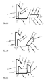
- the profiled rail 1 has a first leg section 10, a second leg section 20 and a bridge section 30, 31 for connecting the first leg section 10 to the second leg section 20. It is provided that the first leg portion 10 has two substantially mutually parallel side webs 11 each having a protruding from the associated side web 11 retaining web 12.
- the holding webs 12 are each designed as a resilient in the direction of the side web 11, sheet-shaped element.
- an abutment element 13 is provided in the form of a substantially perpendicular to the bridge section 30, 31 extending side surface. At this stop element 13 abuts the edge portion of a surface element, when the rail 1 is inserted over the edge portion of a surface element.
- the second leg section 20 is detachably connected to the bridge section 30, 31 and has a profile element 21 which is essentially U-shaped in cross-section and which forms the fastening element when the profile rail is used to produce a multiple glazing unit.
- the fastening element 21 determines a channel, which is open towards the outside with regard to the multiple glazing unit 100, and which is designed to accommodate a support element, not explicitly shown, of a support structure.
- the fastening element 21 has a shape of a U-shaped profile with two side bars 22a and 22b, which are interconnected with a connecting portion 23, which is preferably inclined at an angle of approximately 35 °. It can thus be achieved that in the finished multiple glazing unit 100, for example according to FIGS. 7A and 7B in that the filling material 106 can completely fill the space N between the spacer 105 and the surface elements 101, 102.
- This connection between the bridge portion 30, 31 and the second leg portion 20 serves to easily separate the second leg portion 20 from the bridge portion 30, 31 without damage to the second leg portion 20 when the second leg portion 20 is substantially separated U-shaped profile element 21 in the manufacture of a multiple glazing unit 100 in the groove N formed between two spaced-apart surface elements 101, 102 is held with a filler 106.
- the predetermined breaking point K between the second leg portion 20 and the bridge portion 30, 31 at the end of a step 31 of the bridge portion 30, 31 provided such that the second leg portion 20 with the cross-sectionally substantially U-shaped profile element 21 of a in Fig. 1A shown first position in an in Fig. 1C shown second position (and vice versa) is pivotable, wherein the pivot point in this pivotal movement at the junction K between the bridge portion 30, 31 and the second leg portion 20 is located.
- the second leg portion 20 is substantially perpendicular to the bridge portion 30, 31, whereas in the in Fig. 1A shown at least one side webs 22b of the cross-sectionally U-shaped profile of the fastener 21 is substantially in the plane of the bridge portion 30, 31.
- a latching mechanism 24, 32 is provided, which has a first locking member 24 at the free end of the side bar 22a and a complementary thereto formed second locking member 32 on the bridge section 30, 31.
- the two locking members 24, 32 are - as in Fig. 1B shown - in a preferably releasable (positive engagement) engageable, when the second leg portion 20 is substantially perpendicular to the bridge portion 30, 31.
- the bridge section 30, 31 has a first section 30 and a second section 31 which is step-shaped with respect to the plane in which the first section 30 lies.
- the step-shaped second portion 31 of the bridge portion 30, 31 forms a cover for the cross-sectionally substantially U-shaped profile element 21, so that between the side bars 22 a, 22 b and the Connecting portion 23 lying open channel of the substantially U-shaped profile element 21 is then covered accordingly.
- This cover formed with the second portion 31 of the bridge portion 30, 31 prevents filling material 106 from entering the space trapped between the side bars 22a, 22b and the connecting portion 23 when the rail 1 is used in manufacturing a multiple glazing unit 100.
- the second section 31 of the bridge section 30, 31 By forming the second section 31 of the bridge section 30, 31 in a step-shaped manner, it is possible to set the depth with which, in the production of a multiple glazing unit 100, the profile element 21 of the second leg section 20, which is essentially U-shaped in cross-section, in FIG is held between the two spaced-apart surface elements 101, 102 of the multiple glazing unit 100 groove formed when the rail 1 with at least one edge portion 101 ', 102' of the two surface elements 101, 102 is non-positively connected, so that the at least one edge portion 101 ', 102 'in a gap formed between the first and the second leg portion 10, 20 P is received and the second leg portion 20 is held in the groove N formed between the two spaced-apart surface elements 101, 102.
- the synopsis shows the FIGS. 1 and 5 to 7 in that in the profile rail 1 according to Fig. 1C the first and second leg sections 10, 20 are formed on the bridge section 30, 31 in such a way that the profile rail 1 can be frictionally connected to at least one edge section 101 ', 102' of the two surface elements 101, 102 forming the multiple glazing unit 100, so that the at least one an edge portion 101 ', 102' is received in the space P formed between the first and second leg portions 10, 20, and the second leg portion 20 is held in the groove N formed between the two spaced-apart surface members 101, 102.
- the holding of the second leg portion 20 in the groove N formed between the two spaced-apart surface elements 101, 102 is used in the manufacture of the multi-glazing unit 100 to position the cross-sectionally substantially U-shaped profile element 21 of the second leg portion 20 in the groove N and provisionally fix before the groove N is filled with the filler 106.
- the first and second leg sections 10, 20 of the profiled rail 1 are formed on the bridge section 30 of the profiled rail 1 in such a way that - as in particular in FIG FIGS. 5A and 5B shown in the manufacture of the multiple glazing unit 100, the rail 1 over at least one edge portion 101 ', 102' of the two surface elements 101, 102 can be plugged, wherein at least one edge portion 101 ', 102' of the two surface elements 101, 102 of the manufactured multiple glazing unit 100 in the between the first and second leg portions 10, 20 can be achieved that with the rail 1, the fastening element 21 in the formed between the respective edge portions 101 ', 102' of the two spaced-apart surface elements 101, 102 groove N are optimally positioned in a particularly easy and error-free manner can.
- At least one first leg portion 10 at least one substantially perpendicular to the bridge portion 30 extending side web 11 with at least one of the side web 11 in the direction of the second leg portion 20 projecting support web 12.
- This embodiment is particularly suitable when the distance L between the at least one side web 11 and the first leg portion 10 facing side of the cross-sectionally substantially U-shaped profile element 21 of the second leg portion 20 is greater than the thickness of the in between the first and second leg portion 10, 20 formed intermediate space P edge portion 101 ', 102' of the surface element 101, 102 is.
- FIGS. 5A and 5B With regard to the profiled rail 1, provision is made in this connection in particular for the at least one retaining web 12 projecting from the side web 11 to be designed such that, when the profiled rail 1 is inserted over the edge section 101 'of the surface element 101, to the first leg section 10 facing side of the surface element 101 abuts, the edge portion 101 'is received in the intermediate space P formed between the first and the second leg portion 10, 20.
- the profiled rail 1 such that at least one first leg section 10 has at least one substantially perpendicular to the bridge section 30 extending side web 11, wherein the distance L between the at least one side web 11 and the first leg portion 10 facing Side of the substantially U-shaped in cross-section profile element 21 of the second leg portion 20 is substantially identical to the thickness of the in between the first and second leg portion 10, 20 formed intermediate space P edge portion 101 ', 102' of the surface element 101, 102 is.
- the profile rail 1 is formed such that the distance L between the at least one side web 11 of the first leg portion 10 and the first leg portion 10 facing side of the cross-section substantially U-shaped formed profile element 21 of the second leg portion 20 is greater than the thickness of the in the formed between the first and second leg portion 10, 20 edge portion 101 ', 102' of the surface element 101, 102, it is preferred that at least one of the at least To perform a side web 11 of the first leg portion 10 projecting retaining web 12 as a resilient in the direction of the associated side web 11, preferably sheet-shaped element. It would be conceivable here, for example, that the at least one holding web 12 projecting from the at least one side web 11 of the first leg section 10 is formed from a flexible material and / or has a soft consistency compared to the material of the side web 11.
- each with different strong surface elements 101, 102 are used, since the distance L between the first and the second leg portion 10, 20 of the rail 1, and thus the size of the between the first and the second leg portion 10, 20 formed gap P, is flexible in a certain range and to the thickness of the male edge portion 101 ', 102' of the surface element 101, 102 adapts.
- FIGS. 5A to 7A as well as in FIGS. 5B to 7B are each different stages in the manufacture of a multiple glazing unit 100 using the in Fig. 1C shown profiled rail 1 shown.
- the profiled rail 1 with the at least one of the at least one side web 11 of the first leg portion 10 projecting holding web 12, which is designed as a resilient towards the associated side web 11, preferably sheet-shaped element, over different thickness edge portions 101 '. of the respective surface element 101 is pluggable, wherein in principle the respective edge portion 101 'in the intermediate space P formed between the first and the second leg portion 10, 20 is positively received.
- Fig. 2 to Fig. 4 described further preferred embodiments of the rail 1, which are suitable in the manufacture of a multiple glazing unit 100, in particular for positioning and provisionally fixing a fastener 21 in a groove N formed between two spaced-apart surface elements 101, 102.
- Fig. 2 is a cross-sectional view of a rail 1 according to a second preferred embodiment shown, which is identical in principle to the rail according to the first preferred embodiment, which, however, in comparison to the rail according to Fig. 1C an extended bridge portion 30, 31 has.
- the step-shaped second section 31 of the bridge section 30, 31 clearly over the opening of the formed with the side bars 22a, 22b and the connecting portion 23 channel of the substantially U-shaped profile element 21, so that the releasable connection (predetermined breaking point K) between the second leg portion 20 and the bridge portion 30, 31 from the free end of the second portion 31 of the bridge portion 30, 31 is present.
- profiled rail 1 thus comes to the bridge portion 30, 31 in addition to the covering function of the cross-sectionally substantially U-shaped profile element 21 in addition to the function of covering the entire overall groove N, if the rail 1 - as in Fig. 5A or Fig. 5B shown - plugged over the edge portion 101 'of the surface element 101, for example, and thus the edge portion 101' is positively received in the space P formed between the first and the second leg portion 10, 20.
- the bridge section 30, 31 is preferably at least as long in cross section as the distance between the surface elements 101, 102 of the multiple glazing unit 100 to be produced, which substantially simplifies the formation of the material ring 106 during the production of the multiple glazing unit 100. Namely, if the rail 1 is frictionally connected to at least one edge portion 101 ', 102' of the two surface elements 101, 102 and the at least one edge portion 101 ', 102' is received in the intermediate space P formed between the first and the second leg portion 10, 20, The bridging section 30, 31 covers the groove N formed between the two spaced-apart surface elements 101, 102, in which the profiled rail 1, which is essentially U-shaped in cross-section, is also held with the profiled rail 1. In the subsequent formation of the material ring 106 by filling a filling material into the groove N, the initially flowable filling material is held in the groove N by means of the groove N overlapping bridge portion 30, 31 until the filler has solidified sufficiently.
- Fig. 3 shows a profiled rail 1 in cross-sectional view according to a third preferred embodiment, which in the manufacture of a multi-glazing unit 100th is particularly adapted to provisionally fix a fastener 21 in a groove N formed between two spaced-apart surface elements 101, 102 at a position at which the fastener 21 is not immediately adjacent to one of the surface elements 101, 102.
- the third embodiment is a profile rail, which has a total of two first leg portions 10, 10 ', which are connected to the bridge portion 30, 31, that the second leg portion 20 between the two first leg portions 10, 10 'is arranged, and that in each case a gap P, P' between one of the first leg portions 10, 10 'and the second leg portion 20 is formed.
- the two first leg sections 10, 10 ' are formed on the bridge section 30, 31 in such a way that the profile rail 1 can be plugged over both edge sections 101', 102 'of the surface elements 101, 102 to be produced in the multiple glazing unit 100, so that in each case one the edge portions 101 ', 102' of the two surface elements 101, 102 are accommodated with the leg portions 10, 10 ', 20, and the second leg portion 20 is held in the groove N between the two spaced surface elements 101, 102 ,
- a fourth preferred embodiment of a rail 1 is shown in cross-sectional view, which substantially the in Fig. 3 shown in the third embodiment, and which in the manufacture of a multiple glazing unit 100 is particularly adapted to simultaneously fix a plurality of fasteners 21 in a formed between two spaced surface elements 101, 102 groove N at a respective position temporarily, in which the fastener 21 is not immediately adjacent to one of the surface elements 101, 102.
- profiled rails 1 are particularly suitable for use in the production of a multiple glazing unit 100 in which a fastening element 21 is arranged in a groove N formed between two spaced-apart surface elements 101, 102, this fastening element 21 being provided by the fixing element 21 Cross section is formed substantially U-shaped profile element 21 of the rail 1.
- Fig. 5 to Fig. 7 the method according to the invention for producing a multiple glazing unit 100 is described. In detail is in Fig. 5 to Fig. 7 shown as using the rail 1 according to Fig. 1C Multiple glazing units 100 each having different strong surface elements 101 can be produced.
- Fig. 5A or. Fig. 5B each shown in a cross-sectional view of an unfinished double glazing unit when clamping a rail 1 according to the first preferred embodiment for positioning and provisionally fixing the fastener 21 in the groove N formed between the two spaced-apart surface elements 101, 102.
- Fig. 6A or. Fig. 6B is in each case in a cross-sectional view in Fig. 5A or.
- Fig. 5B shown double glazing unit 100 after clamping the profile rail 1 and after forming a material ring 106 in the groove N formed between the two spaced-apart surface elements 101, 102, while in Fig. 7A or.
- Fig. 7B each in a cross-sectional view of the finished double glazing unit 100 according to Fig. 5A or. Fig. 5B is shown.
- a profile rail 1 and two preferably glass-like surface elements 101, 102 are provided. Subsequently, the two surface elements 101, 102 are arranged in an opposing and spaced-apart relationship, the distance between the surface elements 101, 102 being defined by a spacer 105 arranged between the surface elements 101, 102, and the two surface elements 101, 102 being arranged in this way be that on the one hand between the spaced surface elements 101, 102 and the spacer 105, a gas space G is included, and that on the other hand with the respective edge portions 101 ', 102' of the surface elements 101, 102 and the spacer 105 is an at least partially circumferentially extending groove N is formed.
- the profile rail 1 is then placed on the formed with the respective edge portions 101 ', 102' of the surface elements 101, 102 and the spacer 105 groove N such that at least one edge portion 101 ', 102' of the two surface elements 101, 102 in the between the first and the second leg portion 10, 20 of the rail 1 formed gap formed P and the second leg portion 20 of the rail 1 is held in the formed between the two spaced surface elements 101, 102 groove N.
- a material ring 106 is formed in the groove N. This is preferably done by a filling material is introduced into the groove N such that the second leg portion 20 of the rail 1 is at least partially enclosed by the filler material.
- a filling material is introduced into the groove N such that the second leg portion 20 of the rail 1 is at least partially enclosed by the filler material.
- Fig. 6A or. Fig. 6B the multiple glazing unit 100 is shown with an already formed material collar 106.
- FIGS. 7A and 7B In each case, in a cross-sectional view, the finished multiple glazing unit 100 is shown, which has the two spaced-apart surface elements 101, 102, wherein the first surface element 101 forms, for example, the inner pane of the glazing unit 100.
- the gas space G is delimited between the surface elements 101, 102 by the circumferentially extending spacer 105, which is formed of galvanized steel, for example, and between the spacer 105 and each of the disks 101, 102 is preferably a layer of a sealing material, such as polyisobutylene, can be laid.
- FIG Fig. 7A or. Fig. 7B the material ring 106 is provided, which fills the space N between the spacer 105 and the surface elements 101, 102, and which holds the two surface elements 101, 102 together.
- the fixing element 21 is immersed in the filling material 106.
- Fig. 7A or. Fig. 7B shown finished multiple glazing unit 100 are the free ends of the fastening element forming side bars 22a, 22b substantially flush with the edge of the two surface elements 101, 102 at;
- the invention is not limited to such a flush concern. Rather, it is possible by the use of the rail 1, the fastener 21, if necessary, to position deeper in the groove N or at other positions within the groove N.
- the fastening element 21 should have a width which is preferably less than half the distance between the spaced-apart surface elements 101, 102. This can ensure that when forming the material ring 106, the filling material with a sufficiently large surface of the respective surface elements 101, 102 come into contact so as to provide a reliable bond.
- the invention is not limited to the preferred embodiment of the rail 1 shown in the drawings. Rather, any combination of the individual features specified in the claims with respect to the rail 1 are conceivable.
- the inventive method for producing a multiple glazing unit 100 is not limited to the use of the in Fig. 1C limited shown rail.
- the profile rail is preferably made of a plastic, in particular polyethylene, polypropylene or polyethylene terephthalate.
- a plastic in particular polyethylene, polypropylene or polyethylene terephthalate.
- polyethylene polyethylene
- polypropylene polypropylene
- polyethylene terephthalate polyethylene terephthalate
Landscapes
- Engineering & Computer Science (AREA)
- Civil Engineering (AREA)
- Structural Engineering (AREA)
- Securing Of Glass Panes Or The Like (AREA)
- Joining Of Glass To Other Materials (AREA)
- Automatic Assembly (AREA)
- Automobile Manufacture Line, Endless Track Vehicle, Trailer (AREA)
Priority Applications (8)
| Application Number | Priority Date | Filing Date | Title |
|---|---|---|---|
| EP07101933A EP1956174B1 (fr) | 2007-02-07 | 2007-02-07 | Rail de profilé destiné au positionnement d'un élément de fixation et procédé de fabrication d'une unité de vitrification multiple |
| ES07101933T ES2325186T3 (es) | 2007-02-07 | 2007-02-07 | Riel perfilado para posicionar un elemento de fijacion y procedimiento para fabricar una unidad de acristalamiento multiple. |
| AT07101933T ATE428840T1 (de) | 2007-02-07 | 2007-02-07 | Profilschiene zum positionieren eines befestigungselements und verfahren zum herstellen einer mehrfachverglasungseinheit |
| PT07101933T PT1956174E (pt) | 2007-02-07 | 2007-02-07 | Guia perfilada para posicionar um elemento de fixação e processo de fabrico de uma unidade de vidraça múltipla |
| DE502007000616T DE502007000616D1 (de) | 2007-02-07 | 2007-02-07 | Profilschiene zum Positionieren eines Befestigungselements und Verfahren zum Herstellen einer Mehrfachverglasungseinheit |
| US12/526,257 US8702082B2 (en) | 2007-02-07 | 2008-02-06 | Profile rail for positioning a fixing element and method for producing a multiple glazing unit |
| PCT/EP2008/051432 WO2008095946A2 (fr) | 2007-02-07 | 2008-02-06 | Rail profilé pour positionner un élément de fixation et procédé de fabrication d'une unité de vitrage multiple |
| CA 2677628 CA2677628C (fr) | 2007-02-07 | 2008-02-06 | Rail profile pour positionner un element de fixation et procede de fabrication d'une unite de vitrage multiple |
Applications Claiming Priority (1)
| Application Number | Priority Date | Filing Date | Title |
|---|---|---|---|
| EP07101933A EP1956174B1 (fr) | 2007-02-07 | 2007-02-07 | Rail de profilé destiné au positionnement d'un élément de fixation et procédé de fabrication d'une unité de vitrification multiple |
Publications (2)
| Publication Number | Publication Date |
|---|---|
| EP1956174A1 true EP1956174A1 (fr) | 2008-08-13 |
| EP1956174B1 EP1956174B1 (fr) | 2009-04-15 |
Family
ID=38291234
Family Applications (1)
| Application Number | Title | Priority Date | Filing Date |
|---|---|---|---|
| EP07101933A Not-in-force EP1956174B1 (fr) | 2007-02-07 | 2007-02-07 | Rail de profilé destiné au positionnement d'un élément de fixation et procédé de fabrication d'une unité de vitrification multiple |
Country Status (8)
| Country | Link |
|---|---|
| US (1) | US8702082B2 (fr) |
| EP (1) | EP1956174B1 (fr) |
| AT (1) | ATE428840T1 (fr) |
| CA (1) | CA2677628C (fr) |
| DE (1) | DE502007000616D1 (fr) |
| ES (1) | ES2325186T3 (fr) |
| PT (1) | PT1956174E (fr) |
| WO (1) | WO2008095946A2 (fr) |
Cited By (2)
| Publication number | Priority date | Publication date | Assignee | Title |
|---|---|---|---|---|
| ITVR20120054A1 (it) * | 2012-03-22 | 2013-09-23 | Aluk Group S P A | Struttura di facciata per edifici |
| EP3299563A1 (fr) * | 2016-09-23 | 2018-03-28 | AGC Glass Europe | Élément en verre isolant armé |
Families Citing this family (1)
| Publication number | Priority date | Publication date | Assignee | Title |
|---|---|---|---|---|
| PT1956174E (pt) * | 2007-02-07 | 2009-07-16 | Alcoa Aluminium Deutschland In | Guia perfilada para posicionar um elemento de fixação e processo de fabrico de uma unidade de vidraça múltipla |
Citations (5)
| Publication number | Priority date | Publication date | Assignee | Title |
|---|---|---|---|---|
| GB948032A (en) | 1960-12-22 | 1964-01-29 | Detag | Multiple glass panes |
| FR2222523A1 (en) | 1973-03-23 | 1974-10-18 | Caillon Robert | U-section frame for double glazing - is low density material with silicone filler packing and sealing the frame |
| DE3626194A1 (de) * | 1986-08-01 | 1988-02-04 | Schuermann & Co Heinz | Fassadenverkleidung |
| DE19547444A1 (de) | 1994-12-22 | 1996-06-27 | Glaverbel | Mehrfachverglasungseinheit und Verfahren zu deren Herstellung |
| EP1335079A1 (fr) * | 2002-02-11 | 2003-08-13 | Reynolds Architectuursystemen | Panneau de façade, son procédé de fabrication et son usage dans un mur rideau |
Family Cites Families (28)
| Publication number | Priority date | Publication date | Assignee | Title |
|---|---|---|---|---|
| US3751868A (en) * | 1970-07-27 | 1973-08-14 | A Mascioletti | Structure for the assembly of fixtures for doors, windows and the like |
| GB1523457A (en) * | 1974-11-02 | 1978-08-31 | Dynamit Nobel Ag | Hollow extruded member for use in door or window frame construction |
| USD260075S (en) * | 1979-02-28 | 1981-08-04 | Baker Sr George H | Drapery channel |
| US4258519A (en) * | 1979-03-19 | 1981-03-31 | Andrew Hugens | Means for joining panels |
| NL8006689A (nl) * | 1980-12-09 | 1982-07-01 | Wavin Bv | Kunststofbeglazingsprofiel. |
| JPS5924878U (ja) * | 1982-08-09 | 1984-02-16 | ワイケイケイ株式会社 | 建物の壁体 |
| AT391514B (de) * | 1986-01-30 | 1990-10-25 | Interprofil Gfk Gmbh | Fensterrahmenprofil und verfahren zur herstellung eines solchen fensterrahmenprofils |
| DE3644704A1 (de) * | 1986-12-30 | 1988-07-14 | Fukubi Kagaku Kogyo Kk | Aus extrudierten formteilen zusammengefuegter fensterrahmen |
| GB8811613D0 (en) * | 1988-05-17 | 1988-06-22 | Yang T H | Clamping set having doublecoordinate clamping function & being extensible for adjusting clamp depth |
| GB2246385A (en) * | 1990-07-28 | 1992-01-29 | David Edward Rawlings | Improvements in or relating to the manufacture of thermal break frame sections |
| CA2041364C (fr) * | 1991-04-26 | 1993-09-21 | Glenn Robert Allen | Vitrage isolant pour montage en affleurement |
| WO1993021400A1 (fr) * | 1992-04-16 | 1993-10-28 | Farag F Aziz | Systeme de murs-rideaus joints bout a bout sans butee |
| US5355645A (en) * | 1992-08-26 | 1994-10-18 | Farag F Aziz | Stopless butt-joint multiple curtainwall system |
| FR2704596B1 (fr) * | 1993-04-29 | 1995-07-21 | Orme Sarl | Element pour encadrement de panneau, constitue de deux profiles et profiles correspondants. |
| US5857298A (en) * | 1993-10-29 | 1999-01-12 | Fullwood; James | Window frame system |
| US5884361A (en) * | 1994-10-06 | 1999-03-23 | Anthony's Manufacturing Company | Slider door mechanism, running gear mechanism and closure return |
| US5758870A (en) * | 1996-05-07 | 1998-06-02 | Mega Technology E.D.M., Inc. | Ergonomic clamp pin handle cover |
| DE19641127A1 (de) * | 1996-10-05 | 1998-04-09 | Meissner & Wurst | Reinraumdecke, vorzugsweise Rasterdecke |
| US6393778B1 (en) * | 1997-07-03 | 2002-05-28 | Raymond M. L. Ting | Airloop window system |
| US6170214B1 (en) * | 1998-06-09 | 2001-01-09 | Kenneth Treister | Cladding system |
| JP3183281B2 (ja) * | 1999-03-26 | 2001-07-09 | ニチハ株式会社 | 縦張り用外壁板の施工金具,施工構造,及び施工方法 |
| US7380384B2 (en) * | 2001-04-19 | 2008-06-03 | Jean Bourly | Layout for shop window construction, as well as a window frame, glazed door and/or similar, composed of such a layout |
| SE519443C2 (sv) * | 2002-01-21 | 2003-02-25 | Jerker Lundgren | Glasningssystem för byggnader |
| FR2838127A1 (fr) * | 2002-04-08 | 2003-10-10 | Atofina | Surfaces metalliques revetues de polyamide |
| US6893012B2 (en) * | 2003-05-23 | 2005-05-17 | Valtra, Inc. | Quick release cantilever clamp |
| ITTO20030812A1 (it) * | 2003-10-16 | 2005-04-17 | Creare Org S R L | Elemento allungato di un'intelaiatura per un sistema a pannello comprendente un materiale in foglio flessibile. |
| PT1956174E (pt) * | 2007-02-07 | 2009-07-16 | Alcoa Aluminium Deutschland In | Guia perfilada para posicionar um elemento de fixação e processo de fabrico de uma unidade de vidraça múltipla |
| CN101614653B (zh) * | 2008-06-25 | 2012-06-20 | 鸿富锦精密工业(深圳)有限公司 | 拿取光学镜片的治具 |
-
2007
- 2007-02-07 PT PT07101933T patent/PT1956174E/pt unknown
- 2007-02-07 DE DE502007000616T patent/DE502007000616D1/de active Active
- 2007-02-07 EP EP07101933A patent/EP1956174B1/fr not_active Not-in-force
- 2007-02-07 AT AT07101933T patent/ATE428840T1/de active
- 2007-02-07 ES ES07101933T patent/ES2325186T3/es active Active
-
2008
- 2008-02-06 CA CA 2677628 patent/CA2677628C/fr not_active Expired - Fee Related
- 2008-02-06 WO PCT/EP2008/051432 patent/WO2008095946A2/fr not_active Ceased
- 2008-02-06 US US12/526,257 patent/US8702082B2/en not_active Expired - Fee Related
Patent Citations (5)
| Publication number | Priority date | Publication date | Assignee | Title |
|---|---|---|---|---|
| GB948032A (en) | 1960-12-22 | 1964-01-29 | Detag | Multiple glass panes |
| FR2222523A1 (en) | 1973-03-23 | 1974-10-18 | Caillon Robert | U-section frame for double glazing - is low density material with silicone filler packing and sealing the frame |
| DE3626194A1 (de) * | 1986-08-01 | 1988-02-04 | Schuermann & Co Heinz | Fassadenverkleidung |
| DE19547444A1 (de) | 1994-12-22 | 1996-06-27 | Glaverbel | Mehrfachverglasungseinheit und Verfahren zu deren Herstellung |
| EP1335079A1 (fr) * | 2002-02-11 | 2003-08-13 | Reynolds Architectuursystemen | Panneau de façade, son procédé de fabrication et son usage dans un mur rideau |
Cited By (3)
| Publication number | Priority date | Publication date | Assignee | Title |
|---|---|---|---|---|
| ITVR20120054A1 (it) * | 2012-03-22 | 2013-09-23 | Aluk Group S P A | Struttura di facciata per edifici |
| EP3299563A1 (fr) * | 2016-09-23 | 2018-03-28 | AGC Glass Europe | Élément en verre isolant armé |
| WO2018054655A1 (fr) * | 2016-09-23 | 2018-03-29 | Agc Glass Europe | Vitrage isolant renforcé |
Also Published As
| Publication number | Publication date |
|---|---|
| CA2677628C (fr) | 2015-04-14 |
| US8702082B2 (en) | 2014-04-22 |
| DE502007000616D1 (de) | 2009-05-28 |
| WO2008095946A2 (fr) | 2008-08-14 |
| WO2008095946A3 (fr) | 2008-10-16 |
| CA2677628A1 (fr) | 2008-08-14 |
| US20100181713A1 (en) | 2010-07-22 |
| PT1956174E (pt) | 2009-07-16 |
| ES2325186T3 (es) | 2009-08-27 |
| EP1956174B1 (fr) | 2009-04-15 |
| WO2008095946A8 (fr) | 2008-12-18 |
| ATE428840T1 (de) | 2009-05-15 |
Similar Documents
| Publication | Publication Date | Title |
|---|---|---|
| EP1555376A1 (fr) | Profilé composite | |
| DE2750802A1 (de) | Verfahren zur thermischen isolierung und zur verbindung zweier rahmen eines fensterrahmen-aufbaus | |
| EP2476853B1 (fr) | Profil composite pour fenêtres, portes et façades et son procédé de fabrication | |
| DE2910090A1 (de) | Dichtungsstreifen zum abdichten von stossfugen und kreuzungsstellen zwischen bauelementen | |
| DE2727286A1 (de) | Verfahren und vorrichtung zum verbinden flaechenfoermiger bauelemente | |
| EP2467545B1 (fr) | Élément profilé et procédé de fabrication d'un élément profilé | |
| EP2452032A1 (fr) | Aboutement entre les extrémités de dispositifs d'espacement préfabriqués pour du verre isolant et procédé de fabrication correspondant | |
| EP2610412A1 (fr) | Procédé et dispositif d'étanchéification d'un joint de séparation et joint d'étanchéité à ancrage pour un joint de séparation | |
| EP1956174B1 (fr) | Rail de profilé destiné au positionnement d'un élément de fixation et procédé de fabrication d'une unité de vitrification multiple | |
| DE102011002677A1 (de) | Motagehilfseinrichtung für einen Flügel einer Tür, eines Fensters oder dergleichen | |
| EP1918486B1 (fr) | Baguette profilée pour la terminaison de carreaux | |
| DE102012102800B4 (de) | Fugenprofil und Anordnung aus mehreren Fugenprofilen für Fugen in einem Betonbelag | |
| DE19504828C2 (de) | Verfahren zum Herstellen und Verbinden eines Rahmens mit einer Glasscheibe und Vorrichtung zum Durchführen des Verfahrens | |
| EP2899325A1 (fr) | Système d'étanchéification | |
| EP1860250A2 (fr) | Profile d'étanchéité | |
| EP1473418A2 (fr) | Bande d'étanachéité | |
| EP2639395B1 (fr) | Profilé de cadre, battant d'une fenêtre ou d'une porte et procédé de fabrication de celui-ci | |
| DE102004008831B4 (de) | Profil zum Abdecken von Dämmschichten | |
| DE202007000539U1 (de) | Vorrichtung | |
| DE10207351C1 (de) | Verbindungsprofil für zwei Platten | |
| DE10321828A1 (de) | Putzprofilleiste zum Abdichten einer Dehnfuge zwischen zwei Gebäudewänden | |
| DE202019103487U1 (de) | Spreizbarer Eckwinkel | |
| WO2006027082A1 (fr) | Ensemble d'elements comprenant au moins un meneau et au moins deux pieces d'extremite de meneau a integrer dans une vitre isolante | |
| EP1548197A1 (fr) | Dispositif et procédé pour l'étanchéification de joints de constructions, en particulier pour des joints d'expansion de façade | |
| EP3276100A1 (fr) | Système d'étanchéité pour un système de paroi |
Legal Events
| Date | Code | Title | Description |
|---|---|---|---|
| PUAI | Public reference made under article 153(3) epc to a published international application that has entered the european phase |
Free format text: ORIGINAL CODE: 0009012 |
|
| 17P | Request for examination filed |
Effective date: 20080116 |
|
| AK | Designated contracting states |
Kind code of ref document: A1 Designated state(s): AT BE BG CH CY CZ DE DK EE ES FI FR GB GR HU IE IS IT LI LT LU LV MC NL PL PT RO SE SI SK TR |
|
| AX | Request for extension of the european patent |
Extension state: AL BA HR MK RS |
|
| GRAP | Despatch of communication of intention to grant a patent |
Free format text: ORIGINAL CODE: EPIDOSNIGR1 |
|
| GRAS | Grant fee paid |
Free format text: ORIGINAL CODE: EPIDOSNIGR3 |
|
| GRAA | (expected) grant |
Free format text: ORIGINAL CODE: 0009210 |
|
| AK | Designated contracting states |
Kind code of ref document: B1 Designated state(s): AT BE BG CH CY CZ DE DK EE ES FI FR GB GR HU IE IS IT LI LT LU LV MC NL PL PT RO SE SI SK TR |
|
| REG | Reference to a national code |
Ref country code: GB Ref legal event code: FG4D Free format text: NOT ENGLISH Ref country code: CH Ref legal event code: EP |
|
| AKX | Designation fees paid |
Designated state(s): AT BE BG CH CY CZ DE DK EE ES FI FR GB GR HU IE IS IT LI LT LU LV MC NL PL PT RO SE SI SK TR |
|
| REG | Reference to a national code |
Ref country code: IE Ref legal event code: FG4D |
|
| REF | Corresponds to: |
Ref document number: 502007000616 Country of ref document: DE Date of ref document: 20090528 Kind code of ref document: P |
|
| REG | Reference to a national code |
Ref country code: CH Ref legal event code: NV Representative=s name: FELBER & PARTNER AG PATENTANWAELTE |
|
| REG | Reference to a national code |
Ref country code: PT Ref legal event code: SC4A Free format text: AVAILABILITY OF NATIONAL TRANSLATION Effective date: 20090709 |
|
| REG | Reference to a national code |
Ref country code: ES Ref legal event code: FG2A Ref document number: 2325186 Country of ref document: ES Kind code of ref document: T3 |
|
| PG25 | Lapsed in a contracting state [announced via postgrant information from national office to epo] |
Ref country code: LT Free format text: LAPSE BECAUSE OF FAILURE TO SUBMIT A TRANSLATION OF THE DESCRIPTION OR TO PAY THE FEE WITHIN THE PRESCRIBED TIME-LIMIT Effective date: 20090415 Ref country code: FI Free format text: LAPSE BECAUSE OF FAILURE TO SUBMIT A TRANSLATION OF THE DESCRIPTION OR TO PAY THE FEE WITHIN THE PRESCRIBED TIME-LIMIT Effective date: 20090415 |
|
| PG25 | Lapsed in a contracting state [announced via postgrant information from national office to epo] |
Ref country code: LV Free format text: LAPSE BECAUSE OF FAILURE TO SUBMIT A TRANSLATION OF THE DESCRIPTION OR TO PAY THE FEE WITHIN THE PRESCRIBED TIME-LIMIT Effective date: 20090415 Ref country code: SE Free format text: LAPSE BECAUSE OF FAILURE TO SUBMIT A TRANSLATION OF THE DESCRIPTION OR TO PAY THE FEE WITHIN THE PRESCRIBED TIME-LIMIT Effective date: 20090715 Ref country code: SI Free format text: LAPSE BECAUSE OF FAILURE TO SUBMIT A TRANSLATION OF THE DESCRIPTION OR TO PAY THE FEE WITHIN THE PRESCRIBED TIME-LIMIT Effective date: 20090415 Ref country code: IS Free format text: LAPSE BECAUSE OF FAILURE TO SUBMIT A TRANSLATION OF THE DESCRIPTION OR TO PAY THE FEE WITHIN THE PRESCRIBED TIME-LIMIT Effective date: 20090815 Ref country code: PL Free format text: LAPSE BECAUSE OF FAILURE TO SUBMIT A TRANSLATION OF THE DESCRIPTION OR TO PAY THE FEE WITHIN THE PRESCRIBED TIME-LIMIT Effective date: 20090415 |
|
| PG25 | Lapsed in a contracting state [announced via postgrant information from national office to epo] |
Ref country code: DK Free format text: LAPSE BECAUSE OF FAILURE TO SUBMIT A TRANSLATION OF THE DESCRIPTION OR TO PAY THE FEE WITHIN THE PRESCRIBED TIME-LIMIT Effective date: 20090415 Ref country code: EE Free format text: LAPSE BECAUSE OF FAILURE TO SUBMIT A TRANSLATION OF THE DESCRIPTION OR TO PAY THE FEE WITHIN THE PRESCRIBED TIME-LIMIT Effective date: 20090415 Ref country code: RO Free format text: LAPSE BECAUSE OF FAILURE TO SUBMIT A TRANSLATION OF THE DESCRIPTION OR TO PAY THE FEE WITHIN THE PRESCRIBED TIME-LIMIT Effective date: 20090415 |
|
| PLBE | No opposition filed within time limit |
Free format text: ORIGINAL CODE: 0009261 |
|
| STAA | Information on the status of an ep patent application or granted ep patent |
Free format text: STATUS: NO OPPOSITION FILED WITHIN TIME LIMIT |
|
| PG25 | Lapsed in a contracting state [announced via postgrant information from national office to epo] |
Ref country code: SK Free format text: LAPSE BECAUSE OF FAILURE TO SUBMIT A TRANSLATION OF THE DESCRIPTION OR TO PAY THE FEE WITHIN THE PRESCRIBED TIME-LIMIT Effective date: 20090415 |
|
| 26N | No opposition filed |
Effective date: 20100118 |
|
| PG25 | Lapsed in a contracting state [announced via postgrant information from national office to epo] |
Ref country code: BG Free format text: LAPSE BECAUSE OF FAILURE TO SUBMIT A TRANSLATION OF THE DESCRIPTION OR TO PAY THE FEE WITHIN THE PRESCRIBED TIME-LIMIT Effective date: 20090715 |
|
| PG25 | Lapsed in a contracting state [announced via postgrant information from national office to epo] |
Ref country code: GR Free format text: LAPSE BECAUSE OF FAILURE TO SUBMIT A TRANSLATION OF THE DESCRIPTION OR TO PAY THE FEE WITHIN THE PRESCRIBED TIME-LIMIT Effective date: 20090716 Ref country code: MC Free format text: LAPSE BECAUSE OF NON-PAYMENT OF DUE FEES Effective date: 20100301 |
|
| PG25 | Lapsed in a contracting state [announced via postgrant information from national office to epo] |
Ref country code: IT Free format text: LAPSE BECAUSE OF FAILURE TO SUBMIT A TRANSLATION OF THE DESCRIPTION OR TO PAY THE FEE WITHIN THE PRESCRIBED TIME-LIMIT Effective date: 20090415 |
|
| PG25 | Lapsed in a contracting state [announced via postgrant information from national office to epo] |
Ref country code: CY Free format text: LAPSE BECAUSE OF FAILURE TO SUBMIT A TRANSLATION OF THE DESCRIPTION OR TO PAY THE FEE WITHIN THE PRESCRIBED TIME-LIMIT Effective date: 20090415 |
|
| PG25 | Lapsed in a contracting state [announced via postgrant information from national office to epo] |
Ref country code: HU Free format text: LAPSE BECAUSE OF FAILURE TO SUBMIT A TRANSLATION OF THE DESCRIPTION OR TO PAY THE FEE WITHIN THE PRESCRIBED TIME-LIMIT Effective date: 20091016 |
|
| PG25 | Lapsed in a contracting state [announced via postgrant information from national office to epo] |
Ref country code: TR Free format text: LAPSE BECAUSE OF FAILURE TO SUBMIT A TRANSLATION OF THE DESCRIPTION OR TO PAY THE FEE WITHIN THE PRESCRIBED TIME-LIMIT Effective date: 20090415 |
|
| REG | Reference to a national code |
Ref country code: FR Ref legal event code: PLFP Year of fee payment: 9 |
|
| PGFP | Annual fee paid to national office [announced via postgrant information from national office to epo] |
Ref country code: PT Payment date: 20150205 Year of fee payment: 9 Ref country code: IE Payment date: 20150224 Year of fee payment: 9 Ref country code: NL Payment date: 20150223 Year of fee payment: 9 Ref country code: CH Payment date: 20150225 Year of fee payment: 9 Ref country code: LU Payment date: 20150224 Year of fee payment: 9 Ref country code: CZ Payment date: 20150203 Year of fee payment: 9 Ref country code: ES Payment date: 20150326 Year of fee payment: 9 |
|
| PGFP | Annual fee paid to national office [announced via postgrant information from national office to epo] |
Ref country code: GB Payment date: 20150227 Year of fee payment: 9 Ref country code: AT Payment date: 20150226 Year of fee payment: 9 Ref country code: FR Payment date: 20150227 Year of fee payment: 9 |
|
| PGFP | Annual fee paid to national office [announced via postgrant information from national office to epo] |
Ref country code: BE Payment date: 20150218 Year of fee payment: 9 |
|
| PGFP | Annual fee paid to national office [announced via postgrant information from national office to epo] |
Ref country code: DE Payment date: 20150429 Year of fee payment: 9 |
|
| PG25 | Lapsed in a contracting state [announced via postgrant information from national office to epo] |
Ref country code: BE Free format text: LAPSE BECAUSE OF NON-PAYMENT OF DUE FEES Effective date: 20160229 |
|
| REG | Reference to a national code |
Ref country code: DE Ref legal event code: R119 Ref document number: 502007000616 Country of ref document: DE |
|
| PG25 | Lapsed in a contracting state [announced via postgrant information from national office to epo] |
Ref country code: LU Free format text: LAPSE BECAUSE OF NON-PAYMENT OF DUE FEES Effective date: 20160207 |
|
| REG | Reference to a national code |
Ref country code: CH Ref legal event code: PL |
|
| REG | Reference to a national code |
Ref country code: AT Ref legal event code: MM01 Ref document number: 428840 Country of ref document: AT Kind code of ref document: T Effective date: 20160207 |
|
| GBPC | Gb: european patent ceased through non-payment of renewal fee |
Effective date: 20160207 |
|
| PG25 | Lapsed in a contracting state [announced via postgrant information from national office to epo] |
Ref country code: LI Free format text: LAPSE BECAUSE OF NON-PAYMENT OF DUE FEES Effective date: 20160229 Ref country code: CH Free format text: LAPSE BECAUSE OF NON-PAYMENT OF DUE FEES Effective date: 20160229 |
|
| REG | Reference to a national code |
Ref country code: NL Ref legal event code: MM Effective date: 20160301 |
|
| REG | Reference to a national code |
Ref country code: FR Ref legal event code: ST Effective date: 20161028 |
|
| PG25 | Lapsed in a contracting state [announced via postgrant information from national office to epo] |
Ref country code: PT Free format text: LAPSE BECAUSE OF NON-PAYMENT OF DUE FEES Effective date: 20160808 Ref country code: AT Free format text: LAPSE BECAUSE OF NON-PAYMENT OF DUE FEES Effective date: 20160207 Ref country code: CZ Free format text: LAPSE BECAUSE OF NON-PAYMENT OF DUE FEES Effective date: 20160207 |
|
| REG | Reference to a national code |
Ref country code: IE Ref legal event code: MM4A |
|
| PG25 | Lapsed in a contracting state [announced via postgrant information from national office to epo] |
Ref country code: IE Free format text: LAPSE BECAUSE OF NON-PAYMENT OF DUE FEES Effective date: 20160207 Ref country code: FR Free format text: LAPSE BECAUSE OF NON-PAYMENT OF DUE FEES Effective date: 20160229 Ref country code: NL Free format text: LAPSE BECAUSE OF NON-PAYMENT OF DUE FEES Effective date: 20160301 Ref country code: GB Free format text: LAPSE BECAUSE OF NON-PAYMENT OF DUE FEES Effective date: 20160207 Ref country code: DE Free format text: LAPSE BECAUSE OF NON-PAYMENT OF DUE FEES Effective date: 20160901 |
|
| PG25 | Lapsed in a contracting state [announced via postgrant information from national office to epo] |
Ref country code: ES Free format text: LAPSE BECAUSE OF NON-PAYMENT OF DUE FEES Effective date: 20160208 |
|
| REG | Reference to a national code |
Ref country code: ES Ref legal event code: FD2A Effective date: 20181207 |