EP1956295A2 - Dispositif d'allumage pliable - Google Patents
Dispositif d'allumage pliable Download PDFInfo
- Publication number
- EP1956295A2 EP1956295A2 EP06849484A EP06849484A EP1956295A2 EP 1956295 A2 EP1956295 A2 EP 1956295A2 EP 06849484 A EP06849484 A EP 06849484A EP 06849484 A EP06849484 A EP 06849484A EP 1956295 A2 EP1956295 A2 EP 1956295A2
- Authority
- EP
- European Patent Office
- Prior art keywords
- swingarm
- folding
- operating component
- lighter
- arm
- Prior art date
- Legal status (The legal status is an assumption and is not a legal conclusion. Google has not performed a legal analysis and makes no representation as to the accuracy of the status listed.)
- Withdrawn
Links
- 239000002828 fuel tank Substances 0.000 claims abstract description 13
- 230000013011 mating Effects 0.000 claims description 28
- 239000000446 fuel Substances 0.000 claims description 21
- 230000000994 depressogenic effect Effects 0.000 claims description 2
- 230000001681 protective effect Effects 0.000 description 16
- 230000006378 damage Effects 0.000 description 7
- 230000002093 peripheral effect Effects 0.000 description 7
- 208000027418 Wounds and injury Diseases 0.000 description 4
- 208000014674 injury Diseases 0.000 description 4
- 239000011324 bead Substances 0.000 description 3
- 230000006835 compression Effects 0.000 description 3
- 238000007906 compression Methods 0.000 description 3
- 230000005611 electricity Effects 0.000 description 2
- 230000002265 prevention Effects 0.000 description 2
- 229920003002 synthetic resin Polymers 0.000 description 2
- 239000000057 synthetic resin Substances 0.000 description 2
- 239000004677 Nylon Substances 0.000 description 1
- 230000000694 effects Effects 0.000 description 1
- 238000007689 inspection Methods 0.000 description 1
- 239000011810 insulating material Substances 0.000 description 1
- 239000002184 metal Substances 0.000 description 1
- 229920001778 nylon Polymers 0.000 description 1
- 230000010355 oscillation Effects 0.000 description 1
- 230000037361 pathway Effects 0.000 description 1
- 230000000717 retained effect Effects 0.000 description 1
- 230000035807 sensation Effects 0.000 description 1
- 238000000926 separation method Methods 0.000 description 1
- 239000004449 solid propellant Substances 0.000 description 1
- 230000001131 transforming effect Effects 0.000 description 1
Images


Classifications
-
- F—MECHANICAL ENGINEERING; LIGHTING; HEATING; WEAPONS; BLASTING
- F23—COMBUSTION APPARATUS; COMBUSTION PROCESSES
- F23Q—IGNITION; EXTINGUISHING-DEVICES
- F23Q2/00—Lighters containing fuel, e.g. for cigarettes
- F23Q2/16—Lighters with gaseous fuel, e.g. the gas being stored in liquid phase
Definitions
- This invention relates to lighters (igniter) that drive a piezoelectric unit by operation of an operating component and that emit a flame from the tip of a swingarm that extends from the body, and especially relates to folding lighters onto each of which is installed a swingarm with ability to swing to the lighter body.
- lighters have been used for such as lighting gas burners and solid fuels and for igniting fireworks.
- a lighter having a tip pipe (extension) extended in a rod-shape from the body for emitting a flame is well known (Japanese Examined Patent H9-133359 ( Fig. 1 )).
- This lighter possesses in its body a gas tank and a piezoelectric unit operated by an operating component, and by operating the operating component a flame is emitted from the tip of the tip pipe.
- a lighter of this form can safely and easily ignite objects without burning the user, but there is a problem in that comparatively more space is required to store the lighter due to lengthening of the lighter overall form.
- lighters that can be made compact by extending and collapsing from the body a rod-shaped extension for emitting the flame or can be folded when not in use.
- a folding type lighter with a rod-shaped tip component installed with swinging enabled to one end of the body is known (Japanese Examined Patent H5-14172 ( Fig. 2 and 3 )).
- This lighter normally retains the tip component (extension tube) in a folded and swing-enabled position against the body, and at time of use (time of igniting) allows utilization by extending from the body through swinging of the tip component.
- the operating component is installed on the body so as to be positioned between it and the folded tip component.
- This invention considers the above described concerns and has as its purpose the providing of a safe folding lighter that does not inflict injury or damage to a finger or object by compression between the swingarm and lighter body at time of folding the swingarm to make compact, and prevents at such time ignition by inadvertent pressing of the button.
- the folding lighter of this invention is a folding lighter comprising a body that houses a fuel tank and a piezoelectric unit, and possesses at the side surface an operating component exposed to the outside for operating with approximate contemporaneousness the piezoelectric unit and a fuel supply valve that controls supply of fuel from the fuel tank, and a swingarm connected with free swinging to one end of the body, and housing a flame emission nozzle in the vicinity of the opposite end, and opening and closing freely between a housing position being folded against the side surface of the body and a utilizing position being opened at 90 degrees or more from the body, and housing in the body and the swingarm a flexible fuel conduit connected at one end to the fuel tank and connected at the opposite end to the flame emission nozzle, and characterized by further possessing a safety mechanism for preventing folding of the swingarm when a foreign object such as a finger interposes between the swingarm and the operating component at time when the swingarm is being folded to the housing position, with the safety mechanism possessing a swing preventer axially supported by a axle socket
- the second arm can be structured to mate with a portion of the swingarm so as to push open the swingarm by additional pressing of the operating component when the operating component is further pressed from the position preventing its folding.
- the folding lighter of this invention achieves the following effects because it possesses a safety mechanism for preventing the swingarm from being folded at the interposition of a foreign object such as a finger when the swingarm connected for free swinging to one end of the body is being folded to the stored position, with such safety mechanism possessing a first arm extending to a position that intervenes with the operating component and a second arm that prevents the swingarm from being folded when the first arm is pressed by the operating component.
- the swing preventer prevents the swingarm from being folded if a finger or object is interposed between the swingarm and the pushbutton, there is no injury to the finger or damage to the object.
- the pushbutton cannot be inadvertently pressed by a finger or object and therefore there is no danger of ignition.
- the second arm is structured to mate with one portion of the swingarm so as to push open the swingarm by the further pressing of the operating component at time when the operating component is pressed further from a position preventing the swingarm from being folded, even if a finger or object is relatively forcefully interposed between the swingarm and the body, there is enabled additional and reliable preventing of inadvertent ignition, and there is enabled reliable preventing of injury or damage to fingers or objects.
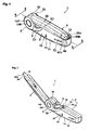
- FIG. 1 is a perspective drawing showing lighter 1 in the folded form.
- Figure 2 is a perspective drawing showing lighter 1 in the form designed to enable use.
- lighter 1 possesses body 2 for grasping with a hand and swingarm 4 axially supported to swing freely at one end of body 2.
- piezoelectric unit 102 Figure 8
- fuel tank 106 Figure 8
- Swing-mount 6 is formed at one end of body 2
- swing-mount mate 10 is formed on one end of swingarm 4 and mounted to swing-mount 6 for support by swing-mount 6.
- Operating button 8 (operating component) is installed in body 2 to be exposed from opening 32 in the vicinity of swing-mount 6. Pressing this operating button 8 with a finger causes ignition.
- inspection window 12 is formed to enable checking of the remaining quantity of a fuel such as a liquefied gas.
- opening 18 is formed in body 2, from which protrudes adjustor protrusion 16 for adjusting the length of the flame to be emitted.
- pipe assembly 20 is housed in swingarm 4 with ability to slide in the lengthwise direction of swingarm 4. When swingarm 4 is in the closed position (housing position), specifically when it is folded to be overlapped by body 2 as shown in Figure 1 , pipe assembly 20 is in a condition pulled within swingarm 4.
- tip tube 20a of pipe assembly 20 is in a condition projected from exposure port 60b of leading edge 4a of swingarm 4.
- Body 2 possesses two reciprocally engaging components, specifically half-body 2a and half-body 2b, and it possesses full-body cover 2c that maintains the reciprocally combined condition of half-bodies 2a and 2b.
- the following section describes half-bodies 2a and 2b and full-body cover 2c by referencing Figures 3 ⁇ 5 .
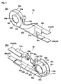
- Figure 3 is a perspective drawing showing half-body 2a which is the forward facing half-body in Figures 1 and 2 , with Figure 3 (a) displaying the half-body 2a shape as seen from the outside and Figure 3 (b) displaying the half-body 2b shape as seen from the inside.
- Figure 4 shows half-body 2b which is the half-body opposite half-body 2a of Figure 3 , with Figure 4 (a) being a front view drawing as seen from the inside and Figure 4 (b) being a perspective drawing also as seen from the inside.
- Figure 5 shows full-body cover 2c, with Figure 5 (a) being a perspective drawing and Figure 5 (b) being a perspective drawing displaying the cross-section along line 5b-5b of Figure 5 (a) .
- half-body 2a is integrally formed from a synthetic resin, for example, and it possesses cylindrically shaped axle 6a (swing axle) structured as part of swing-mount 6.
- axle 6a swing axle
- the half-body possesses circular opening 24a, cylindrically shaped axle socket 30a formed in succession with opening 24a, and annular wall (cylindrical wall) 26a formed at the outer side of axle socket 30a and along the same axis as axle socket 30a.
- cutout 32a is formed to house the upper portion of operating button 8.
- Main section 22a possesses upper wall 34a and lower wall 36a extending approximately in parallel.
- flange sections 38a and 39a are integrally formed to extend on opposite sides of axle 6a.
- the outer surface of main section 22a is formed with channel 37a in a vertical direction for use in positioning full-body cover 2c. Furthermore, the vertical orientation shown here applies to the drawings referenced in the description.
- axle 6a in reference to Figure 3 (b) .
- axle socket 30a At outer surface 31a of axle socket 30a are formed two ribs, specifically stopping sections 40a and 41a, at a prescribed interval.
- notches 42a and 43a In the inner direction of axle 6a and between outer peripheral surface 31a and each of stopping sections 40a and 41a are formed notches 42a and 43a.
- cutout 44a is formed axially inward.
- protrusion 46a is formed to protrude inward in the vicinity of cutout 44a, and in a separated position at the opposite end of main section 22a from protrusion 46a is formed socket seat 50a possessing inward facing elliptical recess 48a.
- Socket seat 50a is the shaft receptacle for operating button 8.
- Half-body 2b is a shape approximately reflective of half-body 2a, and it possesses axle 6b and main section 22b.
- Axle 6b possesses annular wall (cylindrical wall) 26b of the same outer diameter as axle 6a.
- Stopping sections 40b and 41b are on outer peripheral surface 31b of axle socket 30b and correspond to stopping sections 40a and 41a.
- mating section 40 is named to incorporate stopping sections 40a and 41a
- stopper 41 is named to incorporate stopping sections 40a and 41a.
- axle socket 30a within the periphery of axle socket 30b there are formed three reciprocally separated notches 30c, 30d and 30e.
- cutout 32b is formed corresponding to cutout 32a. Moreover, cutouts 32a and 32b enable structuring of single opening 32 for receiving operating button 8 at time of unifying main sections 22a and 22b ( Figures 1 and 2 ).
- protrusion 46b and socket seat 50b are respectively identical to and corresponding to previously described protrusion 46a and socket seat 50a.
- flange sections 38b and 39b are formed in upper wall 34b and lower wall 36b of main section 22b in positions corresponding to previously described flange sections 38a and 39a.
- axle socket 50 is named to incorporate socket seat 50a and socket seat 50b.
- Support sections 38 and 39 are named to incorporate respectively flange sections 38a and 38b and flange sections 39a and 39b.
- channel 37b is formed in main section 22b of half-body 2b corresponding to channel 37a.
- Full-body cover 2c is used by first reciprocally mating the inner surfaces of previously described half-bodies 2a and 2b and then fitting full-body cover 2c over half-bodies 2a and 2b from the opposite end of the combined half-bodies 2a and 2b.
- Full-body cover 2c possesses opening 54 formed by the pair of edges 52 and 52 curved upward at one end.
- opening 54 formed by the pair of edges 52 and 52 curved upward at one end.
- protrude ribs 56a, 56b and 56c within full-body cover 2c are disposed to protrude ribs 56a, 56b and 56c for positioning previously described piezoelectric unit 102 and fuel tank 106 at time of housing ( Figure 8 ).
- Rib 56a is formed as a pair of ribs at left and right in the lengthwise direction of full-body cover 2c, and similarly rib 56b is formed as a pair of ribs at top and bottom in the lengthwise direction ( Figure 8 ). Furthermore, respective opposite side ribs 56a, 56b and 56c are not shown in Figure 5 (b) . Rib 56c is formed vertically at the furthest inner section. In addition, at each inner surface of sidewalls 14, bead 58 is formed for mating respectively to channels 37a and 37b of half-bodies 2a and 2b at time of receiving previously described half-bodies 2a and 2b. Bead 58 is shown for only one side in Figure 5 . By mating beads 58 to channels 37a and 37b, full-body cover 2c is positioned and also fixed.
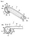
- FIG. 6 shows swingarm 4, with Figure 6 (a) being a perspective drawing and Figure 6 (b) being a front view drawing.
- Swingarm 4 possesses swing-mount mate 10 and long protective cover 60 integrally formed to swing-mount mate 10.
- Protective cover 60 possesses cavity 62 passing through the lengthwise direction within protective cover 60.
- Protective cover 60 is maintained to allow swinging of swingarm 4 without touching tip tube 20a of pipe assembly 20.
- Swing-mount mate 10 is mounted for swinging by interposition support with free swinging between axles 6a and 6b of half-bodies 2a and 2b.
- Swing-mount mate 10 possesses annular wall (cylindrical wall) 26c of approximately the same outer diameter as axles 6a and 6b.
- annular wall 26c annular step 64 is formed for crowning of annular walls 26a and 26b of body 2.
- opening 66 is formed is formed for passage between the interior of annular wall 26c and cavity 62 of protective cover 60.
- arching inner wall (outer cylinder) 70 is integrally supported on the same axis as annular wall 26c by three support walls 68a, 68b and 68c reciprocally separated in the circumferential direction.
- a cylindrical space is formed between arching inner wall 70 and annular wall 26c.
- Support walls 68a and 68c are positioned symmetrically to bind the center arching inner wall 70, and support walls 68b is positioned at the lower end of arching inner wall 70 midway between and 68c.
- axle sockets 30a and 30b are named the inner cylinder in relation to the outer cylinder.
- the upper portion of arching inner wall 70 is a cutout form that specifically becomes opening 66.
- protrusion sections 72a and 72b are formed to protrude facing the body 2 side.
- Protrusion section 72a is formed in the lower section vicinity of support wall 68a and protrusion section 72b is formed in a position approximately identical to that of support wall 68c.
- Swelled protrusions 73 are formed on the leading edges of these protrusion sections 72a and 72b facing inward.
- these swelled protrusions 73 mate at three prescribed angles with notches 30c, 30d and 30e of axle socket 30b of body 2. Specifically, at swingarm 4 operation, this imparts a clicking sensation at the swingarm 4 folded position, the opened utilization position, and a midpoint position. In this way, for lighter 1 in any of various positions or attitudes, there is enabled stable utilization and prevention of swingarm 4 position changes from these prescribed angles.
- protrusion (thick section) 74 is formed at the lower side of annular wall 26c, specifically at support wall 68b.
- Protrusion 74 is formed along the edge at the body 2b side of annular wall 26c and extends from the lower end of annular wall 26c in both directions toward support wall 68a and support wall 68c.
- Protrusion 74 extends slightly toward support wall 68a and extends more than half the distance along the circumference for support walls 68b and 68c.
- arching inner wall 70 is established with rib 76 protruding at a position approximately identical to that of support wall 68.
- arching inner wall 70 is formed with slot 78 directly below rib 76.
- Protective cover 60 possesses metal cap 60a having exposure port 60b. By using latching hooks not shown in the drawing, for example, cap 60a is mated and latched to a recess or hole (not shown in drawing) established in protective cover 60. Furthermore, it is acceptable to use a thermally insulating material such as nylon for cap 60a.
- FIG. 7 This section describes pipe assembly 20 by referencing Figure 7 , with Figure 7 (a) being a perspective drawing and Figure 7 (b) being a component cross section drawing of the region shown by circle 7b in Figure 7 (a) , and both showing the condition in which the gas pipe of the nozzle is inserted into pipe assembly 20.
- Pipe assembly 20 possesses tip tube 20a and tip pipe 20b on which tip tube 20a is installed.
- Tip tube 20a is of cylindrical shape, and it possesses flame port 82 for emitting a flame from the tip.
- Tip pipe 20b is formed of a synthetic resin, for example, and it possesses plate-shaped extension 86 integrally formed to cylinder 84 onto which is installed leading edge tube 20a.
- the tip of extension 8 is formed in a T-shape.
- cylindrical protrusion 88 projects in opposing directions perpendicular to the lengthwise direction of pipe assembly 20 and to channels at both sides.
- nozzle holder 90 is formed to pass through cylinder 84 in tip pipe 20b and to be stored within tip tube 20a.
- space 92 is formed in the lengthwise direction of tip tube 20a. In this space 92 is disposed nozzle (flame emitting nozzle) 94 and gas pipe 96 linked to nozzle 94.
- Nozzle 94 possesses nozzle tip 94a and nozzle body 94b into the tip of which is inserted nozzle tip 94a. This nozzle 94 is fixed to the leading edge of nozzle holder 90 so that nozzle tip 94a is at the outer side of nozzle holder 90. Gas pipe (flexible fuel conduit) 96 is linked by linking pipe 98 to nozzle body 94b of nozzle 94. Nozzle cover 100 is installed at the outer side leading edge of nozzle holder 90 to protect nozzle tip 94a.
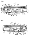
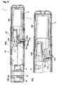
- FIG. 8 is a cross section drawing along line 8-8 of lighter 1 shown in Figure 1
- Figure 9 is a cross section drawing along line 9-9 of lighter 1 shown in Figure 1
- swingarm 4 is overlapping body 2 in the closed condition, specifically the folded condition.
- body 2 Within body 2 is disposed piezoelectric unit 102, housing 104 maintaining piezoelectric unit 102, and fuel tank 106.
- Piezoelectric unit 102 possesses sliding component 102a that is pressed for piezoelectric unit 102 to generate electricity.
- Fuel tank 106 is a cylindrically square component structured to be installed and fixed in housing 104 on the opposite side of piezoelectric unit 102.
- Piezoelectric unit 102 and fuel tank 106 are positioned and retained by previously described ribs 56a, 56b and 56c as well as support sections 38 and 39.
- operating button 8 of body 2 is axially supported for free swinging by axle socket 50 so as to face opening 32 of body 2.
- FIG. 10 shows operating button 8, with Figure 10 (a) being a perspective drawing, Figure 10 (b) being a top view drawing, Figure 10 (c) being a side view drawing, and Figure 10 (d) being a front view drawing.
- Operating button 8 possesses upper wall 108 that in a top view is of transforming shape from circular to elliptical by forming a large arching shape on one side and small arching shape on the other side. The circumference of upper wall 108 is encompassed by peripheral wall 110, and the inner side of peripheral wall 110 becomes a cavity.
- plate 8a is disposed to project to the side direction, and one side of plate 8a, specifically toward the half-body 2b side, L-shaped mating hook (hook component) 8b is formed to extend with upward inclination. At the leading edge of mating hook 8b, protrusion 112 is formed facing inward.
- Plate 8a contacts against the lower edge of one side of opening 32 of body 2 with operating button 8 under the opening. In this way, operating button 8 does not dislodge outward from opening 32.
- the pair of cylindrical shafts 8c used for axle support from axle socket 50 are disposed projecting to a position corresponding to axle socket 50.
- arm 8e is integrally fixed downward from the other side of upper wall 108. At the lower side of this arm 8e, curved protrusion 116 is formed to face sliding component 102a.
- FIGs 8 and 9 there is clearly shown the condition in which swingarm 4 is axially supported by body 2. Specifically, arching inner wall 70 of swingarm 4 is axially supported for free swinging by axle sockets 30a and 30b of half-bodies 2a and 2b. Furthermore, axle socket 30b appears in Figure 8 , and axle socket 30a appears in Figure 9 .
- sleeve 146 is inserted and fixed at the inner side of unified axle sockets 30a and 30b. Sleeve 146 possesses annular recess 147 at both sides ( Figures 1 and 2 ). Additionally, annular step 148 is formed at the outer peripheral edge of respective openings 24a and 24b of half-bodies 2a and 2b, as shown in Figure 3 (a) and Figure 13 .
- annular recess 147 of sleeve 146 is mated to annular step 148, and along with fixing of sleeve 146 within axle sockets 30a and 30b, it supports half-bodies 2a and 2b in a manner that half-bodies 2a and 2b will not be separated.
- FIG. 12 is a cross-sectional perspective drawing showing swing-mount 6 and related vicinity at time when swingarm 4 is in closed condition.
- Mating hook 8b is positioned in the edge vicinity of annular wall 26c
- protrusion 112 of mating hook 8b is positioned in the edge vicinity of the inner side of annular wall 26c of swingarm 4. Therefore, protrusion 74 formed below the edge of annular wall 26c is positioned as separated downwards from mating hook 8b.
- FIG. 9 This section further describes lighter 1 by referencing Figure 9 .
- connector 118 is installed and connected to gas pipe 96 for supplying fuel to gas pipe 96.
- Gas pipe 96 passes through swing-mount 6 and reaches pipe assembly 20.
- Lever (swing preventer) 120 is disposed in a position corresponding to notch 8d of operating button 8. The following describes this lever 120 by additionally referencing Figures 11 and 13 .
- Figure 11 (a) is a perspective drawing
- Figure 11 (b) is a top view drawing
- Figure 11 (c) is a right side view drawing
- Figure 11 (d) is a front view drawing
- Figure 11 (e) is a bottom view drawing.
- Figure 13 is a cross-sectional perspective drawing showing swing-mount 6 and the related vicinity.
- Lever 120 is of a roughly flat and long shape, and cylindrical spindle 120a is disposed projecting in a sideways direction at side edge 124a in the vicinity of one end.
- first arm 121 the section extending toward the side of operating button 8 from spindle 120a
- second arm 123 the section extending toward swing-mount 6
- curved protrusion 120c is formed having joint position with spindle 120a.
- rectangular flange 120b is disposed projecting toward the side on the opposite side of spindle 120a and at the lower surface 128 of side edge 124b.
- first arm 121 On first arm 121 is formed rectangular plate 120d which is larger than rectangular flange 120b.
- Lever 120 is axially supported by spindle 120a in axle socket 122 ( Figure 3(b) ), having rectangular plate 120d at the side toward operating button 8. It is then supported by compression coil spring (hereafter, simply referred to as spring) 130 disposed at the half-body 2a side.
- spring 130 In the lighter 1 assembled condition, notch 8d of operating button 8 is mated to rectangular plate 120d of first arm 121.
- Leading edge 120e of second arm 123 incorporating rectangular flange 120b is mated to slot 78 of arching inner wall 70 of swingarm 4.
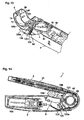
- FIG. 14 is a vertical cross-section drawing similar to Figure 6 and showing a condition in which swingarm 4 of lighter 1 is partially opened.
- Figure 15 is a main component enlarged cross section drawing showing swing-mount 6, operating button 8 and the related vicinity. Referencing Figure 15 , when swingarm 4 is swung for opening, protrusion 88 of pipe assembly 20 separates from mating section 40 and swings clockwise per Figure 14 . This swingarm 4 position is a condition at which swingarm 4 has been opened from the closed position.
- lever 120 mated with operating button 8 swings counterclockwise per Figure 14 .
- leading edge 120e of lever 120 is mated to slot 78 of arching inner wall 70 of swingarm 4.
- operating button 8 presses further downward rectangular plate 120d of lever 120.
- leading edge 120e of lever 120 biases upward rib 76 formed with adjacent contact above slot 78.
- protective cover 60 of swingarm 4 is prevented from shifting further downward.
- operating button 8 enters a condition in which it is hard to press due to resistance of lever 120.
- arm 8e of operating button 8 is pressing sliding component 102a of piezoelectric unit 102 to an extent but not reaching the ignition point.
- Figure 16 is a cross-section drawing similar to Figure 8 and showing a lighter 1 cross-section for a position differing from that of Figure 14 , with Figure 16 (a) being a cross-section of lighter 1 in a condition identical to that of Figure 14 , and Figure 16 (b) being a main component cross-section showing the condition when operating button 8 is further pressed.
- protrusion 74 is positioned in the vicinity of mating hook 8b, but it has not reached the point of mating with mating hook 8b.
- arm 8e of operating button 8 slightly presses sliding component 102a.
- mating hook 8b of operating button 8 mates to protrusion 74.
- protrusion 74 is inserted between protrusion 112 of mating hook 8b and annular wall 26c.
- arm 8e of operating button 8 presses further on sliding component 102a, but not to the point of ignition.
- shaft 8c of operating button 8 must shift within axle socket 50 to the right per Figure 16 (c) , and sliding component 102a must be further pressed by the shifting of operating button 8.
- protrusion 112 of mating hook 8b will not allow shifting because it is mated to protrusion 74.
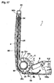
- Figure 17 is a partial cross-section drawing showing the condition in which swingarm 4 is opened at an approximate right angle.
- swelled previously described protrusions 73 of protrusion sections 72a and 72b are respectively mated to notches 30d and 30e, the position of swingarm 4 is maintained in the condition, and protrusion 74 is separated from mating hook 8b. Accordingly, it is possible to consider attempting ignition by pressing operating button 8, but ignition is not normally performed in this position. Even in the event of inadvertent ignition, the flame emitted from flame port 82 of swingarm 4 will not blow near the hand holding body 2 and cause a burn.
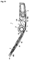
- Figure 18 is a vertical cross-section drawing of lighter 1 showing the condition in which swingarm 4 has been opened approximately 150 degrees
- Figure 19 is a vertical cross-section drawing of lighter 1 showing a cross-section of a position that differs from that of Figure 18 .
- tip tube 20a which will become the nozzle tip 94a edge of pipe assembly 20 enters a condition in which it has protruded from exposure port 60b of protective cover 60 ( Figure 6 (a) ).
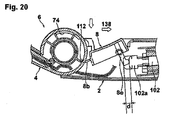
- FIG. 20 is a component enlarged cross-section drawing showing the condition when operating button 8 has been caused to slide.
- arm 8e presses sliding component 102a of piezoelectric unit 102 for a prescribed distance d, and piezoelectric unit 102 generates electricity. This enables causing of an electric discharge in the vicinity of nozzle tip 94a.
- protrusion 74 of swingarm 4 will mate with protrusion 112 of mating hook 8b and generate resistance, preventing closing to less than a prescribed angle. Accordingly, it is possible to prevent such as burns to the hand holding body 2 and scorching of clothing.
- FIG. 21 is a cross-section drawing along line 21-21 of Figure 8 and shows the operating condition of the fuel supply valve, with Figure 21 (a) showing the condition prior to ignition operation, and with Figure 21 (b) being a component cross-section drawing showing the condition after ignition operation.
- Sliding component 102a is positioned at the side of the fuel supply valve, and it possesses lever depressor 102b integrally formed with sliding component 102a along the sliding direction of sliding component 102a. This lever depressor 102b shifts with the shifting of sliding component 102a.
- fuel supply valve 142 is disposed at housing 104.
- Lever 144 Mated to this fuel supply valve 142 is approximately L-shaped lever 144 axially supported for free oscillation to shaft 145 within the space shown.
- Lever 144 possesses mating arm 144a mated to fuel supply valve 142 and drive arm 144b positioned in the vicinity of lever depressor 102b.
- drive arm 144b protrudes within the pathway of level depressor 102b.
- drive arm 144b is pressed by level depressor 102b and moves clockwise per Figure 21 .
- power line 140 ( Figure 8 ) is routed from piezoelectric unit 102 to nozzle 94 and the vicinity of nozzle tip 94a of tip tube 20a, and it releases an electric discharge to ignite the gas emitted from nozzle tip 94a.
Landscapes
- Engineering & Computer Science (AREA)
- Chemical & Material Sciences (AREA)
- Combustion & Propulsion (AREA)
- Mechanical Engineering (AREA)
- General Engineering & Computer Science (AREA)
- Lighters Containing Fuel (AREA)
Applications Claiming Priority (2)
| Application Number | Priority Date | Filing Date | Title |
|---|---|---|---|
| JP2005254867A JP4791784B2 (ja) | 2005-09-02 | 2005-09-02 | 折りたたみ式着火器 |
| PCT/IB2006/004138 WO2007099399A2 (fr) | 2005-09-02 | 2006-08-31 | Dispositif d'allumage pliable |
Publications (1)
| Publication Number | Publication Date |
|---|---|
| EP1956295A2 true EP1956295A2 (fr) | 2008-08-13 |
Family
ID=37926999
Family Applications (1)
| Application Number | Title | Priority Date | Filing Date |
|---|---|---|---|
| EP06849484A Withdrawn EP1956295A2 (fr) | 2005-09-02 | 2006-08-31 | Dispositif d'allumage pliable |
Country Status (5)
| Country | Link |
|---|---|
| US (1) | US7625203B2 (fr) |
| EP (1) | EP1956295A2 (fr) |
| JP (1) | JP4791784B2 (fr) |
| CN (1) | CN102007344B (fr) |
| WO (1) | WO2007099399A2 (fr) |
Cited By (1)
| Publication number | Priority date | Publication date | Assignee | Title |
|---|---|---|---|---|
| CN106091000A (zh) * | 2016-07-29 | 2016-11-09 | 浙江百诚烟具有限公司 | 一种油电混合点火器 |
Families Citing this family (4)
| Publication number | Priority date | Publication date | Assignee | Title |
|---|---|---|---|---|
| WO2018208592A1 (fr) * | 2017-05-08 | 2018-11-15 | Worthington Torch, Llc | Torche dotée d'un mécanisme de verrouillage |
| US11852342B2 (en) * | 2021-01-22 | 2023-12-26 | Pro-Iroda Industries, Inc. | Tool with improved ignition efficiency |
| US11933493B2 (en) * | 2021-01-22 | 2024-03-19 | Pro-Iroda Industries, Inc. | Tool with improved ignition efficiency |
| CN112944392B (zh) * | 2021-03-29 | 2023-07-28 | 深圳市易美生活科技有限公司 | 一种能够360度旋转的点火器及其使用方法 |
Family Cites Families (24)
| Publication number | Priority date | Publication date | Assignee | Title |
|---|---|---|---|---|
| US4536983A (en) * | 1983-08-12 | 1985-08-27 | Fry Daniel J | Reloader for muzzle loaders |
| US4538983A (en) | 1983-10-11 | 1985-09-03 | Noel E. Zeller | Foldable safety lighter |
| JPH0514172A (ja) | 1991-06-28 | 1993-01-22 | Nec Corp | 入力回路 |
| US5199865A (en) * | 1991-08-05 | 1993-04-06 | Liang Chung Ho | Structurre of foldable safety lighter |
| US5597299A (en) * | 1993-05-24 | 1997-01-28 | Jon; Jong K. | Ignition safety device of gas lighter |
| US5697775A (en) * | 1994-08-18 | 1997-12-16 | Tokai Corporation | Safety device in lighting rods |
| JP3516153B2 (ja) | 1995-11-09 | 2004-04-05 | 株式会社東海 | ガス着火器 |
| US5964036A (en) * | 1997-11-12 | 1999-10-12 | Spyderco, Inc. | Folding knife with secondary locking mechanism |
| US6010328A (en) * | 1999-03-26 | 2000-01-04 | Sung; Kil Yong | Double-trigger child-resistant utility lighter |
| JP4317308B2 (ja) * | 2000-02-03 | 2009-08-19 | 株式会社東海 | 点火棒 |
| CA2298176A1 (fr) * | 2000-02-11 | 2001-08-11 | Polycity Enterprise Limited | Allumeur de barbecue avec systeme de securite au gaz |
| US6488492B2 (en) * | 2000-11-03 | 2002-12-03 | Bic Corporation | Multi-mode lighter |
| US7311518B2 (en) * | 2000-11-03 | 2007-12-25 | Bic Corporation | Multi-mode lighter |
| US6916171B2 (en) * | 2000-11-03 | 2005-07-12 | Bic Corporation | Multi-mode lighter |
| US6908302B2 (en) * | 2000-11-03 | 2005-06-21 | Bic Corporation | Multi-mode lighter |
| US6726469B2 (en) * | 2000-11-03 | 2004-04-27 | Bic Corporation | Multi-mode lighter |
| US6971870B2 (en) * | 2000-11-03 | 2005-12-06 | Bic Corporation | Multi-mode lighter |
| US7744368B2 (en) * | 2000-11-03 | 2010-06-29 | Bic Corporation | Multi-mode lighter |
| US6957491B2 (en) * | 2001-10-31 | 2005-10-25 | The Stanley Works | Combination utility and sporting knife |
| US6732436B2 (en) * | 2002-01-10 | 2004-05-11 | Mentor Group Llc | Folding tool |
| US6701621B2 (en) * | 2002-05-08 | 2004-03-09 | Charles L. Kain | Releasable double locking knife |
| JP4282441B2 (ja) * | 2003-11-10 | 2009-06-24 | 株式会社東海 | 着火器具 |
| US7500850B1 (en) * | 2005-07-29 | 2009-03-10 | Colibri Corporation | Lighter with accessory |
| US20070160945A1 (en) * | 2006-01-09 | 2007-07-12 | Huang-Hsi Hsu | Foldable ignition gun |
-
2005
- 2005-09-02 JP JP2005254867A patent/JP4791784B2/ja not_active Expired - Fee Related
-
2006
- 2006-08-31 EP EP06849484A patent/EP1956295A2/fr not_active Withdrawn
- 2006-08-31 WO PCT/IB2006/004138 patent/WO2007099399A2/fr not_active Ceased
- 2006-08-31 CN CN2006800408851A patent/CN102007344B/zh not_active Expired - Fee Related
- 2006-08-31 US US12/065,144 patent/US7625203B2/en not_active Expired - Fee Related
Non-Patent Citations (1)
| Title |
|---|
| See references of WO2007099399A2 * |
Cited By (2)
| Publication number | Priority date | Publication date | Assignee | Title |
|---|---|---|---|---|
| CN106091000A (zh) * | 2016-07-29 | 2016-11-09 | 浙江百诚烟具有限公司 | 一种油电混合点火器 |
| CN106091000B (zh) * | 2016-07-29 | 2018-07-17 | 浙江百诚烟具有限公司 | 一种油电混合点火器 |
Also Published As
| Publication number | Publication date |
|---|---|
| JP4791784B2 (ja) | 2011-10-12 |
| CN102007344A (zh) | 2011-04-06 |
| US20080220385A1 (en) | 2008-09-11 |
| US7625203B2 (en) | 2009-12-01 |
| CN102007344B (zh) | 2012-07-04 |
| JP2007064604A (ja) | 2007-03-15 |
| WO2007099399A2 (fr) | 2007-09-07 |
Similar Documents
| Publication | Publication Date | Title |
|---|---|---|
| US20100190121A1 (en) | Foldable igniter | |
| US6095799A (en) | Utility lighter | |
| US6095796A (en) | Double-button piezoelectric child-resistant cigarette lighter | |
| EP1941882A2 (fr) | Briquet repliable | |
| US6682341B2 (en) | Child resistant actuator for piezoelectric lighter | |
| US6527546B1 (en) | Utility lighter | |
| US6431853B1 (en) | Lighter | |
| EP1956295A2 (fr) | Dispositif d'allumage pliable | |
| CA2413716C (fr) | Mecanisme d'allumage de briquets a systeme coulissant | |
| US6666678B2 (en) | Multi-button piezoelectric child-resistant cigarette lighter | |
| US6422860B2 (en) | Double-button piezoelectric child-resistant cigarette lighter | |
| WO2003085325A1 (fr) | Briquet dote d'un dispositif de blocage | |
| JP7683965B1 (ja) | 着火器具 | |
| US20100047729A1 (en) | Lighter with childproof windshield | |
| JP4942227B2 (ja) | ガスライタ | |
| EP1271055B1 (fr) | Briquet à l'épreuve des enfants | |
| JPH10220756A (ja) | ランタン兼ライターの着火操作装置 | |
| JP3729823B2 (ja) | ガスライター | |
| WO2003098114A1 (fr) | Ameliorations apportees a un briquet | |
| JP2003343832A (ja) | 安全ロック機構を備えた喫煙ライター等の点火装置 | |
| JP2012021728A (ja) | 誤操作防止機構付きガスライター |
Legal Events
| Date | Code | Title | Description |
|---|---|---|---|
| PUAI | Public reference made under article 153(3) epc to a published international application that has entered the european phase |
Free format text: ORIGINAL CODE: 0009012 |
|
| 17P | Request for examination filed |
Effective date: 20080327 |
|
| AK | Designated contracting states |
Kind code of ref document: A2 Designated state(s): AT BE BG CH CY CZ DE DK EE ES FI FR GB GR HU IE IS IT LI LT LU LV MC NL PL PT RO SE SI SK TR |
|
| AX | Request for extension of the european patent |
Extension state: AL BA HR MK RS |
|
| RIN1 | Information on inventor provided before grant (corrected) |
Inventor name: SATO, MAKOTO Inventor name: SUZUKI, TAKAYUKI Inventor name: MOCHIZUKI, TETSUYA |
|
| DAX | Request for extension of the european patent (deleted) | ||
| STAA | Information on the status of an ep patent application or granted ep patent |
Free format text: STATUS: THE APPLICATION IS DEEMED TO BE WITHDRAWN |
|
| 18D | Application deemed to be withdrawn |
Effective date: 20120301 |